Table of Contents
Advertisement
Quick Links
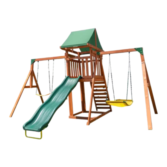
Sherwood Wood Swing Set
Style # (WP-746)
OWNER'S MANUAL
ASSEMBLY, INSTALLATION, CARE, MAINTENANCE AND USER INSTRUCTIONS
WARNING
FOR RESIDENTIAL USE ONL Y
ASSEMBLY REQUIRES AT LEAST FOUR ADULTS
Please keep this instruction manual for future reference.
DO NOT RETURN TO THE STORE
For Customer Service, please call 1-866-370-2131 Mon – Fri 9am – 5pm Eastern Time
or visit www.sportspowerltd.net
Sportspower Limited
Level 20, Parkview Centre, 7 Lau Li Street, Causeway Bay, Hong Kong
Advertisement
Table of Contents

Related Manuals for SPORTSPOWER WP-746


Summary of Contents for SPORTSPOWER WP-746
- Page 1 Sherwood Wood Swing Set Style # (WP-746) OWNER’S MANUAL ASSEMBLY, INSTALLATION, CARE, MAINTENANCE AND USER INSTRUCTIONS WARNING FOR RESIDENTIAL USE ONL Y ASSEMBLY REQUIRES AT LEAST FOUR ADULTS Please keep this instruction manual for future reference. DO NOT RETURN TO THE STORE For Customer Service, please call 1-866-370-2131 Mon –...
- Page 2 INTRODUCTION Dear Valued Customer, Congratulations on your Sherwood Wood Swing Set purchase! Please read and completely understand the contents of this owner’s manual. This manual contains specific instructions that must be followed to prevent injuries. This equipment is for residential use only. This product is NOT intended for public or commercial use.
-
Page 3: Table Of Contents
Trhbrt TABLE OF CONTENTS IMPORTANT WARNINGS AND INSTRUCTIONS ……………………………………………………. . 3 IMPORTANT CONSUMER INFORMATION SHEET …………………………………………………… 8 COMPLETE PRODUCT VIEW…………………………………………………………………………… 13 TOOLS NEEDED …………………………………………………………………………………..……..14 WOOD PARTS LIST…………………………………...……………………………………………..15 HARDWARE PARTS LIST ………………………...……………………………………………………... 17 COMPONENT PARTS LIST ………………………...………………………………………………… ... 18 ASSEMBLY AND INSTALLATION INSTRUCTIONS ……………………………………….…………. -
Page 4: Important Warnings And Instructions
Trhbrt IMPORTANT WARNINGS AND INSTRUCTIONS BEFORE YOU BEGIN: Carefully read all instructions in this manual before assembling and using this product. The unit must be assembled by adults. Heavy duty working gloves must be worn to avoid injuries during assembly. WARNING READ ALL INSTRUCTIONS BEFORE ASSEMBLING OR USING THIS EQUIPMENT AGE LIMIT... - Page 5 Trhbrt IMPORTANT WARNINGS AND INSTRUCTIONS WARNING BEFORE YOU BEGIN ASSEMBLY: Take a complete inventory of components using the parts list. Sort and lay out the wood pieces. Label each piece of wood for easy reference. For easy identification during the assembly process, write the board’s letter on masking tape and adhere to each piece of the wood.
- Page 6 Trhbrt IMPORTANT WARNINGS AND INSTRUCTIONS Carefully read all instructions in this manual before assembling and BEFORE YOU BEGIN: using this product. The unit must be assembled by adults. Heavy duty working gloves must be worn to avoid injuries during assembly. WARNING READ ALL INSTRUCTIONS BEFORE ASSEMBLING OR USING THIS EQUIPMENT Observing the following statements and warnings reduces the likelihood of serious or fatal injury.
- Page 7 Trhbrt IMPORTANT WARNINGS AND INSTRUCTIONS INSPECTION PRIOR TO EACH USE OR DAILY INSPECTION DO NOT use the equipment if any bolts or nuts are missing or loose. ALWAYS check to ensure the equipment and all parts are well secured and stable before each use. ...
- Page 8 Trhbrt WARNINGS AND IMPORTANT INSTRUCTIONS AT THE BEGINNING OF EACH PLAY SEASON: Tighten all hardware. Lubricate all metallic moving parts per manufacturer’s instructions. Check all protective coverings on bolts, pipes, edges, and corners. Replace if they are loose, cracked, or missing.
-
Page 9: Important Consumer Information Sheet
Trhbrt IMPORTANT CONSUMER INFORMATION SHEET The Consumer Product Safety Commission estimates there are about 200,000 playground related injuries involving children each year. Injuries involving this hazard pattern tend to be among the most serious of all playground injuries and have the potential to be fatal, particularly when the injury is to the head. The surface under and around playground equipment can be a major factor in determining the injury-causing potential of a fall. - Page 10 Trhbrt IMPORTANT CONSUMER INFORMATION SHEET The following guidelines are extracts from the Consumer Product Safety Commission Outdoor Home Playground Safety Handbook. It is recommended that you read the entire handbook and take necessary precautions to prevent serious injuries to your children, including: CHOOSING A SITE ...
- Page 11 Trhbrt IMPORTANT CONSUMER INFORMATION SHEET Poured-In-Place Surfaces or Pre-Manufactured Rubber Tiles You may be interested in using surfacing other than loose-fill materials-like rubber tiles or poured-in-place surfaces. Installations of these surfaces generally require a professional and are not “do-it-yourself” projects ...
- Page 12 Trhbrt IMPORTANT CONSUMER INFORMATION SHEET Outdoor Home Playground Safety Checklist Use this to help make your home playground a safe place to play! Supervision Be sure to always supervise children on play equipment. Install a protective surface under and around play equipment to reduce the likelihood of serious head injuries.
- Page 13 Trhbrt IMPORTANT CONSUMER INFORMATION SHEET What to Inspect: Hardware: Inspect all nuts and bolts and tighten if required. Hardware should be firmly against, but not crushing the wood. Over-tightening hardware crushes wood fibers and can split wooden components resulting in the bolt thread extending beyond the wood.
-
Page 14: Complete Product View
Trhbrt COMPLETE PRODUCT VIEW FRONT VIEW OF COMPLETE PRODUCT BACK VIEW OF COMPLETE PRODUCT... -
Page 15: Tools Needed
Trhbrt TOOLS NEEDED These are the tools that are generally required for installation. These tools are not included in the purchased packaging unless stated below. INCLUDED Big Allen Wrench (#6) Small Allen Wrench (#5) -
Page 16: Wood Parts List
WOOD PARTS LIST... - Page 17 WOOD PARTS LIST...
-
Page 18: Hardware Parts List
HARDWARE PARTS LIST NOTE: EXTRA HARDWARE MAY BE INCLUDED Measuring Hardware It is very important that you get the right hardware in the correct place when assembling the unit. You can use a ruler to measure your hardware or you can compare the hardware to the hardware identification page. NOTES: 1) Do not include bolt head when measuring length of bolt. -
Page 19: Component Parts List
Trhbrt COMPONENT PARTS LIST... -
Page 20: Assembly And Installation Instructions
aTrhbrt ASSEMBLY AND INSTALLATION INSTRUCTIONS STEP 1 Part# Hardware# 1 pc 10 pcs 1 pc 4 pcs 1 pc 14 pcs 1 pc 14 pcs 1 pc 1 pc Connect D9 to D3 and D4 using B4, V8 and V9 (4 sets). Connect D10 to D3 and D4 using B4, V8 and V9 (4 sets). - Page 21 Trhbrt ASSEMBLY AND INSTALLATION INSTRUCTIONS STEP 2 Part# Hardware# 2 pcs B2,V8,V9 4 sets 1 pc B2L,V8,V9 4 sets 2 pcs B4,V8,V9 4 sets S2,V20 2 sets Connect D12 to D10 using B2, V8 and V9 (2 sets), and S2 and V20 (2 sets) on back side. ...
- Page 22 Trhbrt ASSEMBLY AND INSTALLATION INSTRUCTIONS STEP 3 Part# Hardware# 1 pc B4,V8,V9 10 sets 1 pc B5,V8,V9 4 sets 1 pc S3,V20 4 sets 1 pc 1 pc 1 pc 1 pc Connect D5 to D1 and D2 using B4, V8 and V9 (4 sets). ...
- Page 23 ASSEMBLY AND INSTALLATION INSTRUCTIONS STEP 4 Part# Hardware# 1 pc S3,V20 8 sets 1 pc Connect D15 to D2 and D14 using S3, V20 (4 sets). Connect D16 to D2 and D3 using S3, V20 (4 sets) as shown.
- Page 24 Trhbrt ASSEMBLY AND INSTALLATION INSTRUCTIONS STEP 5 Part# Hardware# 1 pc 8 pcs 1 pc 8 pcs Connect D15 to D1 and D14 using S3 and V20 (4 sets). Connect D20 to D1 and D4 using S3 and V20 (4 sets) as shown.
- Page 25 Trhbrt ASSEMBLY AND INSTALLATION INSTRUCTIONS STEP 6 Part# Hardware# 1 pc S3,V20 4 sets 2 pcs 4 pcs Connect D21 to D16 and D20 using S3 and V20 (4 sets). Connect D40 to D15, D16 and D20 using S6 (4 pcs) as shown.
- Page 26 Trhbrt ASSEMBLY AND INSTALLATION INSTRUCTIONS STEP 7 Part# Hardware# 1 pc S3, V20 1 set 3 pcs 32 pcs 5 pcs B28,V2,V31 10 sets Connect D22 to D20 using S3 and V20 (1 set). Connect D23 and D24 to D12 and D22 using S6 (32 pcs). Please make sure D23 at the bottom is 4.05 Inch from the edge, and the rest of the boards should be 5.71 Inch apart.
- Page 27 Trhbrt ASSEMBLY AND INSTALLATION INSTRUCTIONS STEP 8 Part# Hardware# 1 pc 30 pcs 8 pcs 1 pc Place all floor boards on the platform and install in the following order: Connect D25 and D27 on the 2 ends using S6 (6 pcs). ...
- Page 28 Trhbrt ASSEMBLY AND INSTALLATION INSTRUCTIONS STEP 9 Part# Hardware# 1 pc S1,V20 4 sets 1 pc S2,V20 6 sets 1 pc S3,V20 2 sets 1 pc S15,V20 2 sets 1 pc B1,V8,V9 1 set Connect D17 to D2 and D3 using S3 and V20 (2 sets). ...
- Page 29 Trhbrt ASSEMBLY AND INSTALLATION INSTRUCTIONS STEP 10 Part# Hardware# 1 pc S1,V20 4 sets 1 pc S2,V20 6 sets 1 pc S3,V20 6 sets 1 pc B1,V8,V9 1 set 1 pc Connect D17 to D1 and D4 using S3 and V20 (2 sets). ...
- Page 30 Trhbrt ASSEMBLY AND INSTALLATION INSTRUCTIONS STEP 11 Part# Hardware# 5 pcs S1,V2 4 sets 1 pc 12 pcs 2 pcs Connect D28 to D10 and D42 using S5 (10 pcs). The distance between the boards should be 2.52 Inch. ...
- Page 31 Trhbrt ASSEMBLY AND INSTALLATION INSTRUCTIONS STEP 12 Part# Hardware# 6 pcs 12 pcs Connect D30 to D29 using S5 (10 pcs). The distance between the boards should be 2.52 Inch. Connect D30 to D31 and D32 using S5 (2 pcs) as shown. The distance between the boards should be 2.76 Inch. ...
- Page 32 Trhbrt ASSEMBLY AND INSTALLATION INSTRUCTIONS STEP 13 Part# Hardware# 2 pcs 6 pcs 2 pcs B1,V8,V9 4 sets 1 pc Connect D33 to D7 using S6 (4 pcs). Connect D8 to D7 using B1, V8 and V9 (4 sets). ...
- Page 33 Trhbrt ASSEMBLY AND INSTALLATION INSTRUCTIONS STEP 14 Part# Hardware# U746 1 pc 8 pcs 1 pc S18,V18,V3 4 sets U10D 1 pc B28,V2,V31 2 sets Connect U746 to D33 using S9 (8 pcs). Attach U10D to U7 using S18, V18 and V3 (4 sets). ...
- Page 34 Trhbrt ASSEMBLY AND INSTALLATION INSTRUCTIONS STEP 15 Part# Hardware# 1 pc 6 pcs 1 pc V7,V1,V6 6 sets 4 pcs B4L,V24,V9 4 sets First, hammer the square head rivets (V4) into the pre-drilled holes as shown below. Connect U2 to D38 using B4L, V24 and V24, V9 (2 sets). Connect U2 to D39 using B4L, V24 and V24, V9 (2 sets).
- Page 35 Trhbrt ASSEMBLY AND INSTALLATION INSTRUCTIONS STEP 16 Part# Hardware# 2 pcs B9,V8,V9 4 sets 2 pcs S3,V20 12 sets 2 pcs 2 pcs Insert B9, V8 through D37, D36 and D35 and fasten with V8, V9 (2 sets) on the other end of screw. ...
- Page 36 Trhbrt ASSEMBLY AND INSTALLATION INSTRUCTIONS STEP 17 Part# Hardware# U101 1 pc V18,V6 4 sets U102 2 pcs U103 2 pcs U104 2 sets ASSEMBLE THE TWO PERSON FLYING SAUCER IN THE FOLLOWING ORDER: Slide U103 tubes into the side pockets of flying saucer U101. ...
- Page 37 ASSEMBLY AND INSTALLATION INSTRUCTIONS STEP 18 Part# Hardware# 2 pcs B1,V24,V9 4 sets B4L,V24,V9 4 sets Connect D39 to D11 with U2 on both sides using B1, V24 and V9 (4 sets). Connect D36 to D39 with U3 using B4L, V24 and V24, V9 (4 sets). Note: Go back and fully tighten the screws on the entire swing set frame.
- Page 38 ASSEMBLY AND INSTALLATION INSTRUCTIONS STEP 19 Part# Hardware# 2 pcs B1,V24,V9 4 sets B4L,V24,V9 4 sets Connect D38 to D11 with U2 on both sides using B1, V24 and V9 (4 sets). Connect D36 to D38 with U3 using B4L, V24 and V24, V9 (4 sets). Note: Go back and fully tighten the screws on the entire swing set frame.
- Page 39 Trhbrt ASSEMBLY AND INSTALLATION INSTRUCTIONS STEP 20 Part# Hardware# 2 sets Hook the swings (U41) to the top frame. Attach the flying saucer (U104) to the frame as shown. IMPORTANT: MAKE SURE ALL HOOKS ARE SECURELY LATCHED BEFORE ALLOWING CHILDREN TO USE.
- Page 40 Trhbrt ASSEMBLY AND INSTALLATION INSTRUCTIONS STEP 21 Part# Hardware# 6 pcs 6 pcs Use U50 as the anchoring stakes for this set. Hammer U50 fully into the ground and secure to the playhouse using S1 (6 pcs) as shown . IMPORTANT: BEFORE ALLOWING CHILDREN TO PLAY ON THE EQUIPMENT, THE ANCHORS PROVIDED MUST BE INSTALLED.
-
Page 41: Product Warranty
(including use by under-age, over-weight or excessive number of users permitted as stated in the User’s Manual). (c) Defects, damages or accidents due to the malfunction, connection to or use of non-Sportspower or unauthorized parts. In such event, Sportspower reserves the right to cancel the Limited Warranty coverage immediately. - Page 42 WARRANTY IS VALID ONLY IN THE UNITED STATES. PLEASE NOTE: ANY REPAIRS OR REPLACEMENTS MUST BE MADE USING AUTHORIZED SPORTSPOWER PARTS IN ORDER FOR THIS WARRANTY TO BE VALID. For Customer Service, please call 1-866-370-2131 Monday – Friday 9:00 AM – 5:00 PM Eastern Time or visit www.sportspowerltd.net...
Need help?
Do you have a question about the WP-746 and is the answer not in the manual?
Questions and answers