
Related Manuals for SystemAir DVG F400


Summary of Contents for SystemAir DVG F400
- Page 1 Installation, Operation and Maintenance instruction DVG F400 Roof fans with AC motor...
-
Page 2: Table Of Contents
Table of content 1 Introduction ���������������������������������������������������������������������1 11�1 To disassemble and discard the parts of the product ������������������������������������������������������������� 11 1�1 Product description ������������������������������������������������������1 12 Warranty ����������������������������������������������������������������������� 11 1�2 Intended use ����������������������������������������������������������������1 1�3 Document description ��������������������������������������������������1 13 Technical data ���������������������������������������������������������������12 1�4 Product overview����������������������������������������������������������1 1�5 Name plate �������������������������������������������������������������������2 13�1... -
Page 3: Introduction
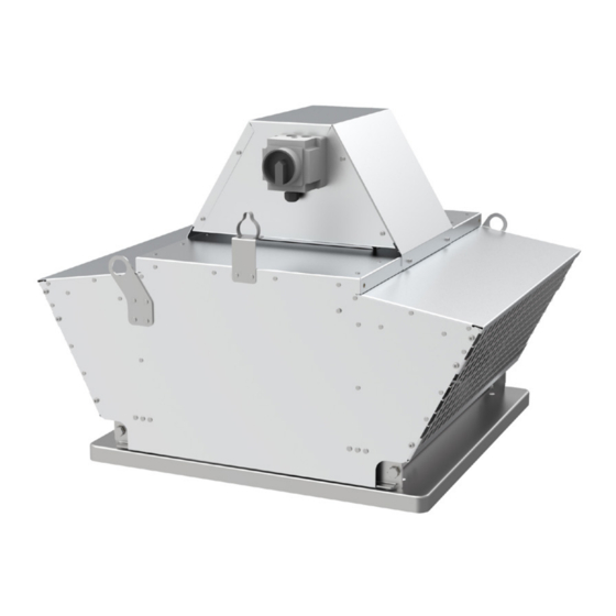
The product is intended for installation in outdoor done by approved personnel only� environments on rooftops and can be connected to a duct system� Speak to Systemair for more information on how to install the product in different installation locations. Product overview 1� Service switch 5�... -
Page 4: Name Plate �������������������������������������������������������������������2 13�1 Technical Data Overview
10� Max. airflow (m 11� Weight, kg Product liability 12� Motor IP class, insulation class Systemair is not liable for damages that the product causes 13� Fire classification; snow load in these conditions: 14� Application; response delay • The product is incorrectly installed, operated or 15�... -
Page 5: Safety
• If the maintenance is not correctly and regularly done, there is risk of injury and damage to the product� • Only do the maintenance as given in this manual� Speak to Systemair technical support if other servicing is necessary� • Always use spare parts from Systemair�... -
Page 6: Transportation And Storage
– To decrease vibrations transmitted from the product to • Before you move the product to the installation location, the duct system, Systemair recommends to install examine the packaging for damages� flexible connections. • Do not move the product by the cables, terminal box, fan –... -
Page 7: To Install The Product
To install the product 1� Systemair recomends to install the product together with roof curb� Put the supplied temperature resistant sealing tape on the contact surface between base plate and the roof� 4.2.1 To open a product with swing out casing, size 315-450 1�... - Page 8 1� To lock the service switch: drill a hole into the service switch handle when it is in the “on-position” and install a padlock� Padlock is not supplied by systemair� Note: Make sure that the flexible connection complies with demanded time - temperature class, if the product is used for extraction of smoke and hot gases�...
-
Page 9: Differential Pressure Monitoring
The commissioning report is found at www�systemair�com� To connect the product to the To do before the power supply commissioning •... -
Page 10: To Do The Commissioning
• Visually examine the product and accessories for necessary to assure operation� Switch on max� speed damage� even after eventual short supply cut off must be assured. • Make sure that the safety devices are correctly installed� • The fans were hot tested with frequency converter and sine filter. However, it is recommended to bridge • Make sure that there are no blockages in the air inlet eventual converter in case of fire (to prevent any error and the air outlet�... -
Page 11: Maintenance
Systemair support� • Do not clean the product with a high- pressure washer� • Always use spare parts from Systemair� • Do not clean the product with steel brushes or sharp objects� • When you send an order for spare parts, include the •... -
Page 12: Troubleshooting
Troubleshooting Note: If you cannot find a solution to your problem in this section, speak to Systemair technical support. Problem Cause Solution The fan impeller is not correctly Speak to Systemair technical support� balanced� There is dirt on the fan impeller� Clean the fan impeller carefully� Refer to 9�2 To clean the product page 9� The fan impeller has damages or Speak to Systemair technical support�... -
Page 13: Of The Product
For warranty claims, send a written maintenance plan and The product follows the WEEE directive� This symbol on the the commissioning report to Systemair� The warranty is only product or the packaging of the product shows that this applicable for these conditions: product is not domestic waste�... -
Page 14: Technical Data
Technical data overview Refer to the name plate� Refer to 1�5 Name plate page 2 for more Electrical data information� Refer to the data sheet in the online catalogue at www�systemair�com� Other data 13.2 Product dimensions 13.2.1 Product dimensions for DVG-H Note: If the unit of measure is not specified, the dimensions are given in millimetres. -
Page 15: 13�2�2 Product Dimensions For Dvg
DVG-H 500, 560 12XM8 1078 DVG-H 630 12XM8 1039 1072 DVG-H 710 12XM8 1050 1124 1280 DVG-H 800 16XM8 1050 1255 1280 13.2.2 Product dimensions for DVG-V n x M Ød3 Ød4 Ød1 Ød2 ØD DVG-V 315, 355 6XM8 1020 DVG-V 400, 450 6XM8 1261... -
Page 16: Inclusive 3
Wiring diagrams 14.1 Wiring diagram for 1 speed fan up to inclusive 3 kW Wiring sizes 630-710, Y/Y, 4/6, 6/8 14.2 Wiring diagram for 1 speed Upper diagram…low speed fan from inclusive 4 kW Lower diagram…high speed 14.4 Wiring diagram for 2 speed fan in Dahlander conection Y 400V…starting D 400V…operation... -
Page 17: Emc Protection
14.5 Wiring diagram for 1 speed 14.6 Service switch fan in EMC protection (on request) Maximum Factory possible (change Switch mounted or add by customer) 1 speed ≤ 9993431 2 x M20 + M12 3 kW 2 speed ≤ M20 + 9993432 2 x M20 + M12 2,2 kW 1 speed ≥ M25 + 930637 M25 + M32 + M16 4 kW 2 speed ≥... -
Page 18: Accessory Overview
FDG/F roof curb 2� FDGE/F roof curb 3� SSGE/F silencer 4� SSG/F silencer 5� ASG/F inflow box 6� VKG/F shutter 7� ASFV flange 8� ASSG/F flexible connection 9� ESDG inlet cone Note: For more information about accessories, refer to www�systemair�com or speak to Systemair technical support�... -
Page 19: Eu Declaration Of Conformity
EU Declaration of Conformity Manufacturer Systemair d�o�o� Špelina 2 Address SI-2000 Maribor Slovenia Product designation Roof fans Smoke and heat extract fans DVG-H-F400, DVG-V-F400, sizes 315, 355, 400, Type/Model 450, 500, 560, 630, 710, 800, thermo roof fans DVG-H/V-T, DVG-120... -
Page 20: Declaration Of Conformity
UK Declaration of Conformity Manufacturer Systemair d�o�o� Špelina 2 Address SI-2000 Maribor Slovenia Product designation Roof fans Smoke and heat extract fans DVG-H-F400, DVG-V-F400, sizes 315, 355, 400, Type/Model 450, 500, 560, 630, 710, 800, thermo roof fans DVG-H/V-T, DVG-120... - Page 22 © Copyright Systemair AB All rights reserved E&OE Systemair AB reserves the rights to alter their products without notice. This also applies to products already ordered, as long as it does not affect the previously agreed specifications. Original instructions 9994879.00...
Need help?
Do you have a question about the DVG F400 and is the answer not in the manual?
Questions and answers