
Related Manuals for SystemAir DVG Series


Summary of Contents for SystemAir DVG Series
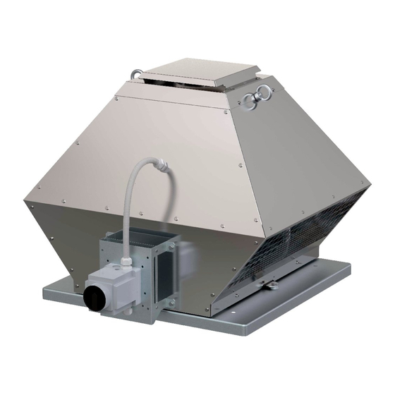
- Page 1 Installation and Operating Instructions for Anvisningar för montering och drift Инструкция по установке и эксплуатации DVG-H DVG-V English Originalversion DVG-H EC DVG-V EC...
- Page 2 Please consider the fact that our products are subject to a natural wear and ageing process. All rights are with Systemair, also for the event of applications for protective rights. Данная инструкция предназначена для описания продукта. Информация об использовании или возможности...
-
Page 3: Table Of Contents
Table of contents General information ........4 Commissioning ......... 10 List of information ........4 Preconditions ..........10 1.1.1 Specific safety symbols ......... 4 Commissioning ..........11 1.1.2 List of instructions for action ......4 8.2.1 Safety elements........... 11 Notes on the documentation ......5 Operation .......... -
Page 4: General Information
General information 1. General information List of information DANGER Direct danger Failure to comply with this warning leads directly to death or to serious bodily harm. WARNING Possible danger Failure to comply with this warning potentially leads to death or to serious bodily harm. CAUTION Hazard with a low risk Failure to comply with this warning potentially leads to moderate injuries. -
Page 5: Notes On The Documentation
Notes on the documentation WARNING Hazard as a result of improper dealing with the fan These operating instructions describe safe use of the fan. Read the operating instructions carefully! Keep the operating instructions with the fan. They must be permanently available at the place of use. 2. -
Page 6: Improper Use
Warranty The maximum permissible operating data on the name plate apply for an air density ρ = 1,2 kg/m³ (sea level) and a maximum air moisture of 80 %. Smoke and heat extract roof fans DVG/F400 are intended to exhaust hot gases up to 400°C/120 min (F400/120, F400/90, F300, F200). -
Page 7: Transport
Transport WARNING Hazard of impact if the fan falls down! Transport the fan carefully and with appropriate hoisting device! Wear a safety helmet and safety goggles! WARNING Electrical hazard from damaged connection cable or connections Do not use the connection cable, service switch or impeller for transport. Transport and unload the wooden crate/cardboard box carefully. -
Page 8: Technical Data
Ensure secure access to the fan for maintenance and service. Mounting of service switch and vertical outlets (DVG-V) up to Appendix 1. Fit the contact surface between base plate and roof base with sealing tape. Systemair roof bases are delivered with appropriate sealing tape. -
Page 9: Electrical Connection
It is recommended to install a flexible connection between the fan and duct to avoid eventual tensions or distortions of the base plate (also as certified Systemair accessorie available). For F400 only: appropriate flexible connection should take possible thermal extension of connecting parts. -
Page 10: Protect The Motor
Commissioning WARNING Hazard from electrical voltage! Electrical connection only by a trained electrician rsp. trained and instructed qualified personnel! Electrical connection in accordance with the valid regulations. Prevent the ingress of water into the connection box. Observe 5 safety rules for the electrical expert! disconnect from the power supply (all-pole), prevent switching on again, test absence of voltage,... -
Page 11: Commissioning
Commissioning WARNING Hazard from electrical voltage! Commissioning by trained and instructed qualified personnel only! Switch the ventilator on as planned. WARNING Hazard from bursting parts! When checking the direction of rotation, wear safety goggles. Check: the direction of rotation (all speed!). Switch the fan for a short period on and then off to check the direction of rotation of impeller. -
Page 12: Operation/Use
Maintenance/trouble setting In case of speed control via frequency converter - min. 20 Hz ÷ max. 50 Hz (rsp. 60 Hz, if declared for 60 Hz), make sure that the voltage peaks on the connection terminals of the fan are lower than 1000 V and voltage rise velocity is lower than 500 V/μs (IEC 34-17). -
Page 13: Malfunctions And Troubleshooting
WARNING Hazard from electrical voltage! At maintenance and service observe: Impeller must stand still. Electrical circuit must be interrupted and secured against restarting. Observe the rules for safe work. CAUTION Danger from hot surfaces! During maintenance and cleaning wear protective gloves! 10.1 Malfunctions and service The ventilator does not... -
Page 14: Spare Parts
Maintenance/trouble setting The fan is by built-in for-life lubricated ball bearings as far as possible low-maintenance product. After their life time (app. 30.000 to 40.000 h), a replacement of the bearings is necessary. Observe attached instructions of motor manu- facturer. Pay attention to a non-typical noise from bearings. -
Page 15: Uninstalling/Dismounting
Uninstalling/dismounting WARNING Hazard from electrical voltage! Switching off and uninstalling only by a trained electrician or trained and instructed qualified person- nel! Observe 5 safety rules for the electrical expert! disconnect from the power supply (all-pole), prevent switching on again, test absence of voltage, earthing and short-circuiting, protect adjacent live parts by covers and barriers and fit a suitable warning notice. -
Page 16: Appendix 1: Mounting Of Service Switch, Mounting Of Vertical Outlets At Dvg-V
Appendix 1: Mounting of service switch / Mounting of vertical outlets at DVG-V See IMO, Section 7 Properly mounted service switch, cable protected inside tube DVG 13.12.2016... -
Page 17: Appendix 2: Wiring Diagrams
Appendix 2: Wiring diagrams Single speed motor up to inclusive 4 kW output power, 4 pole, 6 pole, 8 pole Single speed motor, DVG-H/V 400D4V/F400 DVG 13.12.2016... - Page 18 2 speed motor in Dahlander connection, 4-8 pole Y400V…low speed, YY400V…high speed Single speed motor with star – delta starting (motors with output power more than 4 kW) Starting in Y, operation in D Warning: it is not 2 speed motor! 2 speed motor with separated windings, 4-6, 6-8 pole 1U, 1V, 1W…low speed...
-
Page 19: Appendix 3: Wiring Diagrams Dvg-Ec 1
Appendix 3: Wiring diagrams DVG-EC 1~ DVG 13.12.2016... - Page 20 DVG 355-EC, DVG 450-EC – Wiring 1~, 230V, 50/60Hz……..27.11.2013 Terminals 4 to 23 (lower markings in the connection box) are led from controller out to outer connection box. 3 bridges are factory inserted to allow test of fan without connecting control cables.
-
Page 21: Appendix 4: Wiring Diagrams Dvg-Ec 3
Appendix 4: Wiring diagrams DVG-EC 3~ DVG 13.12.2016... - Page 22 DVG 560-EC, DVG 630-EC, DVG 800-EC – Wiring 3~, 400V, 50/60Hz……..27.11.2013 Terminals 1 to 17 (lower markings in the connection box) are led from controller out to outer connection box. 3 bridges are factory inserted to allow test of fan without connecting control cables.
-
Page 23: Appendix 5: Accessories Dvg-H - Mounting
Appendix 5: Accessories DVG-H - mounting DVG-H DVG-H SSG/F VKG/F SSG/F ASG/F VKG/F ASG/F ASSG/F ASSG/F DVG-H DVG-H VKG/F VKG/F ESDG SSGE/F (FDGE/F) FDG/F ASG/F ASSG/F DVG 13.12.2016... -
Page 24: Appendix 6: Accessories Dvg-V - Mounting
Appendix 6: Accessories DVG-V - mounting DVG-V DVG-V VKG/F SSG/F SSG/F ASG/F ASG/F VKG/F ASSG/F ASSG/F DVG-V DVG-V VKG/F VKG/F SSGE/F ESDG (FDGE/F) FDG/F ASG/F ASSG/F DVG 13.12.2016... -
Page 25: Appendix 7: Sealing Of Cable Glands
Appendix 7: Sealing of cable glands no wire 1x blind plug D8 1x wire up to D5,3 mm 1x multiwire sealing insert 2x blind plug D5 2x wire up to D5,3 mm 1x multiwire sealing insert 1x blind plug D5 3x wire up to D5,3 mm 1x multiwire sealing insert no blind plug...
Need help?
Do you have a question about the DVG Series and is the answer not in the manual?
Questions and answers