
Related Manuals for SystemAir DVN


Summary of Contents for SystemAir DVN
- Page 1 Roof fans DVN(I), DVS(I), DVC(I), DHS Installation and Operating Instructions Document in original language | · 006...
- Page 2 © Copyright Systemair AB All rights reserved E&OE Systemair AB reserves the rights to alter their products without notice. This also applies to products already ordered, as long as it does not affect the previously agreed specifications. | 006...
-
Page 3: Table Of Contents
5 rules of electrical safety ......2 Warranty ............2 Delivery, transport, storage .......2 Description ............3 Intended use .........3 Technical data ........3 Description DVN/DVNI ......4 Description DVS/DVSI ......5 Description DVC/DVCI......6 Description DHS ........7 Name plate and type key ........8 Accessories............9 Installation........... 10 Installation of the ventilation system .......... -
Page 5: General Information
Installation, disassembly Fitter or matching qualification Electrical expert or matching Fitter or matching Maintenance qualification qualification Electrical expert or matching Fitter or matching qualification qualification Repair Smoke extraction fans and EX fans only by agreement with Systemair. | 006... -
Page 6: Personal Protective Equipment
Further prerequisites are a completed maintenance plan with no gaps and a commissioning re- port. Systemair will require these in the case of a warranty claim. The commissioning report is a component of this document. The maintenance plan must be created by the operator, see section 12.2 Maintenance, page 18. -
Page 7: Description
• The fans are intended for installation in ventilation systems. They can be installed both in duct systems and also with free suction via an inlet cone and a suction-side contact protection grille. Systemair recommends a Back draft damper (VKS) to avoid cold air intake at a standstill of the fan, see 7 Accessories, page 9. -
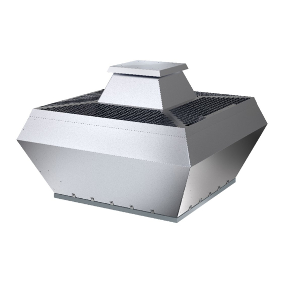
Page 8: Description Dvn/Dvni
| Description Description DVN/DVNI Table 2 Dimensions DVN M20x1,5 I(4x) [mm] 355—400 6xM8 18.5 12(4x) 450—500 6xM8 18.5 12(4x) 560—630 1150 8xM8 14(4x) 1350 1178 1035 8xM8 14(4x) 800—900 1690 1180 1255 1050 8xM8 14(4x) Table 3 Dimensions DVNI [mm] 355—400... -
Page 9: Description Dvs/Dvsi
Description | Description DVS/DVSI Table 4 Dimensions DVS M20x1,5 [mm] 190–225 6xM6 10(4x) 310–311 6xM8 10(4x) 355–400 6xM8 12(4x) 450–500 6xM8 12(4x) 560–630 1150 8xM8 14(4x) 1350 1185 1035 8xM8 14(4x) Table 5 Dimensions DVSI [mm] 190–225 6xM6 10(4x) 310–311 6xM8 10(4x) 355–400... -
Page 10: Description Dvc/Dvci
| Description Description DVC/DVCI S-Version: The DVC-S version can be stepless controlled via a 0-10 V signal. The operating point can be directly adjusted with the integrated potentiometer (10 K ohms). POC-Version The DVC-POC version has integrated pressure sensors and temperature sensor for outdoor temperature compensation. The electronics can be programmed for a constant pressure operation with or without outdoor temperature compensa- tion (The factory setting is with outdoor temperature compensation). -
Page 11: Description Dhs
Description | Table 9 Dimensions DVC-P/DVC-POC M20x1,5 [mm] 190–225 6xM6 10 (4x) 6xM8 10 (4x) 355–400 6xM8 12 (4x) 450–500 6xM8 12 (4x) 560–630 1150 8xM8 14(4x) Table 10 Dimensions DVCI-P/DVCI-POC [mm] 6xM6 10(4x) 6xM6 10(4x) 355–400 6xM8 12(4x) 450–500 6xM8 12(4x) 560–630... -
Page 12: Name Plate And Type Key
| Name plate and type key Name plate and type key 400 V Type designation Enclosure class/fan impeller speed/weight Voltage/current/frequency Insulation class Input power Article number/production number/manufacturing date Max. temperature of transported air Certifications Table 12 Type key Motor type Electronically commutated/1 phased or 3 phased 2 poled/controllable by frequency converter/1 phased 4 poled/controllable by frequency converter/1 phased... -
Page 13: Accessories
Accessories | Accessories For details of the accessories, please check our online catalog or contact Systemair. Table 13 Accessories 1a DVN, DVNI Roof fan - vertical discharge - high temperature - (insulated) 1b DVS/DVSI Roof fan - vertical discharge - standard - (insulated) -
Page 14: Installation
| Installation Installation Safety information ♦ Observe 2 Important safety information, page 1 ♦ Use installation material with fire resistance classes that meet temperature requirements. ♦ Provide contact and intake protection and ensure safety distances according to DIN EN ISO13857 and DIN 24167-1. ♦... -
Page 15: Dvc-P Measuring Tubes
The ball bearing of the motor and the balanced impeller may be damaged by forceful impacts. ♦ Attach the impeller and/or the shaft extension to the shaft or the rotor without forceful impacts. ♦ Do not separate the impeller and the hub. They were balanced as one unit by Systemair. Note: The hub can be heated for easier assembly and disassembly, for example with a hot-air blower. - Page 16 | Installation Disassembly 1. Aluminium hub 1. Steel hub Assembly 5. Aluminium hub Use screw locking The set screw must push on the wedge Use screw locking of the shaft. 5. Steel hub 6. Steel hub Tighten the two screws evenly with the tightening torque according to table Tighten the screws...
-
Page 17: Assembly Tilting Device (Ftg)
Electrical connection | Assembly tilting device (FTG) Leaking duct system. Danger of injury by tilting the fan during installation. ♦ The tilting device must be secured in the opened state ♦ When installing the roof fan and accessories, all by screws in the designated hole against mounting surfaces have to be sealed air tight. -
Page 18: Electrical Connection Accessories
0...10V/PWM Controll via switching on / off The following fans are equipped with a DIN1 connection: DVC(I) 560... DVC(I) 710... DVN(I) 500EC... DVC(I) 630... DVN(I) 450EC-K... DVN(I) 560EC... Din1: enable electronics • enable: pin open or voltage 5–50 V DC •... -
Page 19: Protecting The Motor
♦ Never exceed the maximum impeller rotation speed indicated on the name plate of the fan. ♦ In any case Systemair recommends an all-pole sine filter if the fan is operated with a frequency converter. ♦ For the following fans an all-pole sine filter is mandatory to avoid damages:... -
Page 20: Troubleshooting/Maintenance/Repair
Mechanical blockage Remove the blockage. Rebalancing by a specialist company if possible, Impeller imbalance otherwise contact Systemair. Soiling on the impeller Clean carefully, rebalance Material decomposition on the Contact Systemair impeller due to aggressive material conveyed. - Page 21 Improve cooling. Electronics/motor Check if the correct fan is used for your application. Overloaded motor overheated Ambient temperature too high Check if the correct fan is used for your application. Note: For all other damage/defects, please contact Systemair. | 006...
-
Page 22: 12.2 Maintenance
Check the flexible connectors for damage. See normal operating conditions Spare parts ♦ Use original spare parts from Systemair only. ♦ When ordering spare parts, please specify the serial number of the fan. This can be found on the name plate. Cleaning Safety information ♦... -
Page 23: Fans
Germany Product designation: Thermo fans Type designation: AxZent; KBR; MUB-K; MUB/T; MUB/T-S; DVN; DVNI 2018 Since year of manufacture: The manufacturer declares that the above mentioned products in their design and construction and the version marketed by us complies with the harmonization legislation listed below:... -
Page 24: Commissioning Report
| Commissioning Report Commissioning Report Warranty claims can only be made if commissioning work is carried out correctly and written evidence thereof is provided. Description: Article no.: Manufacturing order no.: Installer Company: Contact person: Company address: Tel. no.: Email: Operator (Place of installation) Company: Contact person: Company address:... - Page 25 Commissioning Report | Fan impeller speed [rpm]: Current L1 [A]*: Current L2 [A]: Air volume [m3/s]: Current L3 [A]: Differential pressure [Pa]*: *For single-phase fans, fill in line “Current L1 [A]” *Δ- Pressure between suction-side and discharge of the fan If an air flow measurement is not possible, this value can be calculated using the following formula: Flow speed [m/s] Duct cross-section [m²]...
- Page 26 Systemair GmbH Seehöfer Str. 45 97944 Boxberg Germany Tel.: +49 (0)7930/9272-0 Fax: +49 (0)7930/9273-92 info@systemair.de www.systemair.de...
Need help?
Do you have a question about the DVN and is the answer not in the manual?
Questions and answers