
Related Manuals for SystemAir DVN 355


Summary of Contents for SystemAir DVN 355
- Page 1 Installation, Operation and Maintenance instruction DVN/DVNI High Temperature Roof fan AC/EC DVS/DVSI Roof fan AC DVC-P/DVCI-P Roof fan EC DVC-POC/DVCI-POC Roof fan EC DHS Roof fan AC...
-
Page 2: Table Of Contents
Table of content 1 Introduction ............1 10 Disposal............16 Product description ........1 10.1 To disassemble and discard the parts of the Intended use ..........1 product............ 16 Document description........1 11 Warranty ............16 Product overview......... 2 12 Technical data ........... 17 1.4.1 Product overview DVN, DVNI, 12.1... -
Page 3: Introduction
The DVC-P fan has an EC motor and an integrated pressure control device for constant pressure control. Speak to Systemair for more information on how to install the product in different installation locations. The DVCI-P fan has an EC motor and an integrated pressure control device for constant pressure control. -
Page 4: Product Overview
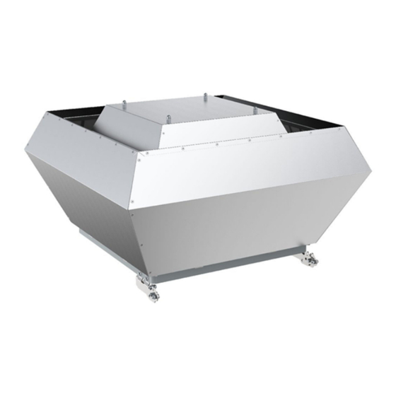
Product overview 1.4.1 Product overview DVN, DVNI, DVS, DVSI, DVC-S, DVCI-S, DVC-POC and DVCI-POC Casing Base plate Top lid Name plate with airflow direction arrow Motor (for DVS and DVSI fans) Integrated pressure controller (DVC-POC and DVCI- POC fans) Connection box 10. -
Page 5: Product Overview Dvc-P And Dvci-P
1.4.2 Product overview DVC-P and DVCI-P Casing Base plate Top lid Name plate with airflow direction arrow Motor Pressure controller (P-models have the controller out- side of the casing) Bird protection grille Fan impeller... -
Page 6: Product Overview Dhs
Weight, kg Serial number: part number/production number/produc- tion date IP class, enclosure class 10. Current, A 11. Voltage, V Use a mobile device to scan the scannable code and go to the Systemair documentation portal for more documentation and document translations. -
Page 7: Type Designation
Note: The data on the name plate applies to “standard air” that is specified in the standard ISO5801. 1.5.1 Type designation Product DVN/DVNI DVS/DVSI DVC-S/ DVC-P/ DVC-POC/ DVN EC/ name DVCI-S DVCI-P DVCI-POC DVNI EC Dimension Motor type DV: 4–pole, EZ: 2–pole, EC: Elec- EC: Elec-... -
Page 8: Product Liability
Product liability Safety Systemair is not liable for damages that the product causes Safety definitions in these conditions: • The product is incorrectly installed, operated or Warnings, cautions and notes are used to point out specially maintained. important parts of the manual. -
Page 9: Personal Protective Equipment
–10 and +30 °C. A stable ambient • Sound levels exceeding 70 dB(A) may occur depending temperature prevents damage from condensation. on model and size. Visit www.systemair.com for more de- tailed information about your product. • Keep the product in storage for maximum 1 year. -
Page 10: Installation
Systemair recommends that the product is installed to- Installation gether with an FTG tilting device. If an FTG tilting device is used, do these steps: To do before the installation Drill holes in the base plate of the fan. of the product Warning •... -
Page 11: To Connect The Product To The Ventilation System
Install the duct and attach the product, with the installed FTG tilting device, on the top of the roof curb. Systemair recommends to connect the duct (D) to a flexi- ble connection (C), an inflow box (B) and a back draft damper (A). -
Page 12: Pressure Controller
If you install the product near a duct bend, do these Electrical connection steps to prevent vibrations, unwanted noise and de- creased air pressure: To do before the electrical Measure the distance (A) between the product and connection the duct bend. Make sure that the distance (A) is a minimum 2.5 x •... -
Page 13: Speed Controller For Ec Motors
EC motors have an integrated motor protection. Reset the The commissioning report is found at www.systemair.com. motor protection by disconnecting the fan from power supply for 60 seconds. To do before the commissioning •... -
Page 14: Operation
EC motors must be set to ON/OFF via the control input. To stop the product via mains supply decreases the life time of the motor. Systemair recommends to install external speed controller for easy access to control the input signal. -
Page 15: To Clean The Product
Spare parts • For information about spare parts, send an e-mail to support@systemair.com. • For more information about spare parts, contact Systemair support. • Always use spare parts from Systemair. • When you send an order for spare parts, include the serial number of the product. -
Page 16: Troubleshooting
Troubleshooting Note: If you cannot find a solution to your problem in this section, speak to Systemair technical support. Problem Cause Solution The fan impeller is not correctly Speak to Systemair technical support. balanced. There is dirt on the fan impeller. - Page 17 This is not applicable for EC motors or 3–phase AC motors. There is blockage in the motor. Speak to Systemair technical support. Defective motor winding. If it is possible, measure the resistance to do a check of the motor winding.
-
Page 18: Disposal
For warranty claims, send a written maintenance plan and product or the packaging of the product shows that this the commissioning report to Systemair. The warranty is only product is not domestic waste. The product must be recycled applicable for these conditions: at an approved disposal location for electrical and electronic •... -
Page 19: Technical Data
12.1 Technical data overview Max. temperature of transported air, °C Max. ambient temperature, °C Refer to the data sheet in the online catalogue at www.systemair.com. Sound pressure, dB IP class Voltage, current, frequency, enclosure Refer to the name plate. Refer to 1.5 Name plate page 4... -
Page 20: Product Dimensions Dvs Fans And Dvsi Fans
ØK ØL (4x) 1350 1178 M20- DVN 710 (8x) x1.5 (4x) 1690 1460 1180 1050 M20- DVN 800 (8x) x1.5 (4x) 1690 1460 1180 1050 M20- DVN 900 (8x) x1.5 (4x) M20- 18.5 DVNI 355 (6x) x1.5 (4x) M20- 18.5 DVNI 400 (6x) x1.5... -
Page 21: Product Dimensions Dvc-S Fans And Dvci-S Fans
ØI ØJ 6xM6 M20x1.5 10(4x) DVS 190 6xM6 M20x1.5 10(4x) DVS 225 6xM6 M20x1.5 10(4x) DVS 310 6xM8 M20x1.5 10(4x) DVS 311 6xM8 M20x1.5 10(4x) DVS 315 6xM8 M20x1.5 12(4x) DVS 355 6xM8 M20x1.5 12(4x) DVS 400 6xM8 M20x1.5 12(4x) DVS 450 6xM8 M20x1.5... -
Page 22: Product Dimensions Dvc-P Fans And Dvci-P Fans
ØI ØJ 6xM6 M20x1.5 10(4x) DVC-S 190 6xM6 M20x1.5 10(4x) DVC-S 225 6xM6 M20x1.5 10(4x) DVC-S 315 6xM6 M20x1.5 12(4x) DVC-S 355 6xM6 M20x1.5 12(4x) DVC-S 400 6xM6 M20x1.5 12(4x) DVC-S 450 6xM6 M20x1.5 12(4x) DVC-S 500 1150 8xM6 M20x1.5 14(4x) DVC-S 560 1150... - Page 23 ØH ØJ DVC-P M16- M16- 6xM6 10(4x) x1.5 x1.5 DVC-P M16- M16- 6xM6 10(4x) x1.5 x1.5 DVCI-P M16- M16- 6xM6 10(4x) x1.5 x1.5 DVCI-P M16- M16- 6xM6 10(4x) x1.5 x1.5 ØI ØK DVC-P M20- M20- 6xM8 10(4x) x1.5 x1.5 DVC-P M20- M20- 6xM8...
-
Page 24: Product Dimensions Dvc-Poc Fans And Dvci-Poc Fans
ØI ØK DVC-P M20- M20- 6xM8 12(4x) x1.5 x1.5 DVC-P M20- M20- 6xM8 12(4x) x1.5 x1.5 DVC-P M20- M20- 6xM8 12(4x) x1.5 x1.5 DVC-P 1150 M20- M20- 8xM8 14(4x) x1.5 x1.5 DVC-P 1150 M20- M20- 8xM8 14(4x) x1.5 x1.5 DVC-P 1350 1185 M20-... -
Page 25: Product Dimensions Dhs Fans
ØI ØJ DVC-POC 6xM8 M20- 10(4x) x1.5 DVC-POC 6xM8 M20- 12(4x) x1.5 DVC-POC 6xM8 M20- 12(4x) x1.5 DVC-POC 6xM8 M20- 12(4x) x1.5 DVC-POC 6xM8 M20- 12(4x) x1.5 DVC-POC 1350 1185 1035 8xM8 1035 M20- 14(4x) x1.5 DVCI-POC 6xM8 M20- 10(4x) x1.5 DVCI-POC 6xM8... - Page 26 ØA ØD ØJ ØK (4x) 6xM6 M20- DHS 190 x1.5 6xM6 M20- DHS 225 x1.5 6xM6 M20- DHS 310 x1.5 6xM6 M20- DHS 311 x1.5 6xM6 M20- DHS 315 x1.5 6xM8 M20- DHS 355 x1.5 6xM8 M20- DHS 400 x1.5 6xM8 M20- DHS 450...
-
Page 27: Wiring Diagrams
Grey Green/Yellow 12.3.1 Wiring diagrams for DVN fans and DVNI fans AC DVN fans DVNI fans 1–phase 230 V DVN 355 E4 DVNI 355 E4 TK TK DVN 355 EV DVNI 355 EV TK TK Z1 DVN 400 E4 DVNI 400 E4... -
Page 28: Wiring Diagrams For Dvs Fans, Dvsi Fans And Dhs Fans Ac
DVN fans DVNI fans 3–phase 230 V 3–phase 400 V DVN 355 D4 DVNI 355 D4 DVN 355 D6 DVNI 355 D6 DVN 355 DV DVNI 355 DV TK TK DVN 400 D4 DVNI 400 D4 TK TK DVN 400 D4... -
Page 29: Wiring Diagrams For Dvn Fans And Dvni Fans Ec
DVS fans DVSI fans DHS fans 1–phase 230 V TK TK DVS 400 E6 DVSI 400 E6 DHS 400 E6 DVS 500 E4 DVSI 500 E4 TK TK DVS 500 E6 DVSI 500 E6 DVS fans DVSI fans DHS fans 3–phase 400 V DVS 311 DV DVSI 311 DV... - Page 30 DVN fans DVNI fans 1–phase 230 V DVN 355 EC DVNI 355 EC DVN 400 EC DVNI 400 EC 0-10V COM NC +10V 0-10V +10V Mains supply, phase (Section 1) Neutral (Section 1) C. Earth (Section 1) D. Alarm relay, COMMON (Section 1) Alarm relay, brake for failure (Section 1) Voltage output +10 V max.
- Page 31 Digital input 2 (switch day/night). Parameters can be selected via BUS or via digital. (KL3) – Day: Pin open or applied voltage 5...50 VDC – Night: Bridge to GND or applied voltage ‹1 VDC Digital input 3 (switch normal/inverse). The preset effective direction of the integrated controller can be selected via BUS or via digital input Normal/Inverse.
- Page 32 RS485 interface for ebmBUS; RS A (KL3) RS485 interface for ebmBUS; RS B (KL3) C. RS485 interface for ebmBUS; RS A (KL3) D. RS485 interface for ebmBUS; RS B (KL3) Ground (KL3) Control/actual value input (KL3) G. Control/actual value input (KL3) H.
-
Page 33: Wiring Diagrams For Dvc-S Fans And Dvci-S Fans Ec
Digital input 2 (switch day/night). The preset set of parameters can be selected via BUS or via digital. (KL3) – Day: Pin open or applied voltage 5...50 VDC – Night: Bridge to GND or applied voltage ‹1 VDC Digital input 3 (switch normal/inverse). The preset effective direction of the integrated controller can be selected via BUS or via digital input Normal/Inverse. - Page 34 DVC-S fans DVCI-S fans 1–phase 230 V DVC 190E–S EC DVCI 190E–S EC DVC 225E–S EC DVCI 225E–S EC 1-10V DVC 315E–S EC DVCI 315E–S EC Connection for maximum speed Connection for adjustable speed using an external potentiometer: – 10 V > n = maximum –...
-
Page 35: Wiring Diagrams For Fans With Pressure Controller
DVC-S fans DVCI-S 3–phase 380–480 V DVC 450D–S EC DVCI 450D–S EC DVC 500D–S EC DVCI 500D–S EC NC COM RSB RSA GND 0-10V +10V 0-10V Error signal relay/alarm 0-10 V potentiometer, pre-wired: – 10 V > n = maximum –... -
Page 36: Wiring Diagrams For Speed Controller For Ac Motors
Pressure controller PCA–2 1000 Signal relay (terminals: 13, 14) Supply voltage (terminals: U , GND) Output signal 0...10 V (terminals: A, GND) Cable gland M16 “Minus” — connection in areas with lower pressure “Plus” + connection in areas with higher pressure Digital input D1 (terminals: 1, 2) Input outdoor temperature sensor (terminals: TF, TF) MODBUS interface (terminals: GND, A, B, ID1, ID2 and jumper J1) - Page 37 REE — Thyristor REE 1 and REE 2 - Surface mounting or with flush mounting casing included. REE 4 - Surface mounting. Note: Starting currents must be considered when you select the speed controller type. Products that are used with this speed controller must have a built-in overheating protec- tion and must be designed for thyristor speed control.
- Page 38 Relay connection. There is always 230 V between ~ and N when the transformer knob is in one of the positions 1–5. Mains supply C. Earth D. Fan Thermostat Motor protection. If the motor protection is not in use, Tk must be looped together. FRQ5S-E-6A Frequency converter with built-in all-pole sine filter and 5-step switch.
- Page 39 RTRD A 3-phase transformer that controls the fan speed by altering the supply voltage in five fixed steps. The steps are adjusted by using the control knob on the front of the unit. RTRD2-7 FS FS TK TK 230 V AC If the function is not necessary, the terminals must be bridged Contact rating, 230 V AC/maximum 1 A C.
-
Page 40: Wiring Diagrams For Speed Controllers For Ec Motors
RTRDU Manual 5–step transformer with motor protection — a 3–phase transformer that controls the fan speed by altering the supply voltage in five fixed steps. The steps are adjusted by using the control knob on the front of the unit. RTRDU FS FS TB TB... - Page 41 MTP 20 MTP 20 1/Vdc+ +10V 4/Vout 0...10V 2/Vdc- 3/Vout- EC-Basic EC-Basic 1/IN Vac 230V AC 2/IN Vac +10V 4/Out 0...10V 5/GND MTV–1/10 MTV 1/010 1/IN Vac 230V AC 2/IN Vac +10V 4/Out+ 0...10V 5/Out- S-5EC/FRQ MTP 10 +10V 0...10V EC-Vent optional IN/RPM...
-
Page 42: Wiring Diagrams For On/Off Controls For Ec Motors
12.3.8 Wiring diagrams for ON/OFF controls for EC motors CO2RT-R(-D) Supply +10V 24V AC Neutral 0...10V Common Relay NO Relay NC Din1 IR24–P +10V 24V AC or DC Neutral 0...10V Common Relay NO Relay NC Din1 12.3.9 Wiring diagrams for demand control for EC motors EC Basic EC Basic-T for temperature control EC-Basic... - Page 43 EC-Vent Demand control for up to 5 external sensors, 2 fans, damp- ers, heaters and coolers. The EC vent system has 2 units. The control board (CB) and the room unit (RU). Connect the fan to the control board and optional IN/RPM TACH...
- Page 44 Control Board (CB) ALARM FAN OUT3 OUT2 OUT1 DEBUG PT1000 +24VDC PT1000 Y +0-10V PT1000 Br + 24VDC N out N in L out L in Mains supply, 230 V 1~AC (10 A) Analogue sensor (for example, pressure sensor) C. Analogue sensor (for example, pressure sensor type PT1000) D.
-
Page 45: Accessory Overview
0 = Setpoint 1 1 = Setpoint 2 Mains supply 10..24 V DC Output 0..10 V Pressure connections Voltage input for switch on Setpoint 1/Setpoint 2 Accessory overview Note: For more information about accessories, refer to www.systemair.com or speak to Systemair technical support. - Page 46 VKS: Back draft damper ASF: Inlet flange SSD: Roof curb FTG: Tilting device ASK: Inflow box SSD TDA: Adapter framework VKS: Back draft damper VKM: Back draft damper (motor operated) ASS: Flexible connection 10. FDS: Flat roof curb...
-
Page 47: Eu Declaration Of Conformity-Roof Fans
EU Declaration of Conformity-Roof fans We, the manufacturer Company Systemair GmbH Address Seehöfer Straße 45 97944 Boxberg Germany declare under our sole responsibility that the product Product designation Roof fans Type/Model DVS 190–710; DVSI 190–710; DHS 190–710; DVC 190–710; DVCI 190–710; DVP 200–400... -
Page 48: Eu Declaration Of Conformity-Thermo Fans
EU Declaration of Conformity-Thermo fans We, the manufacturer Company Systemair GmbH Address Seehöfer Straße 45 97944 Boxberg Germany declare under our sole responsibility that the product Product designation Thermo fans Type/Model AxZent; KBR; MUB/T; MUB/T-S; DVN; DVNI Identification Serial numbers dating from 2022 and onwards... -
Page 49: Ukca Declaration Of Conformity-Roof Fans
UKCA Declaration of Conformity-Roof fans We, the manufacturer Company Systemair GmbH Address Seehöfer Straße 45 97944 Boxberg Germany declare under our sole responsibility that the product Product designation Roof fans Type/Model DVS 190–710; DVSI 190–710; DHS 190–710; DVP 200–400; DVC 190–710; DVCI 190–710... -
Page 50: Ukca Declaration Of Conformity-Thermo Fans
UKCA Declaration of Conformity-Thermo fans We, the manufacturer Company Systemair GmbH Address Seehöfer Straße 45 97944 Boxberg Germany declare under our sole responsibility that the product Product designation Thermo fans Type/Model AxZent; KBR; MUB/T; MUB/T-S; DVN; DVNI Identification Serial numbers dating from 2022 and onwards... - Page 52 © Copyright Systemair AB All rights reserved Systemair AB reserves the rights to alter their products without notice. This also applies to products already ordered, as long as it does not affect the previously agreed specifications. Document in original language...
Need help?
Do you have a question about the DVN 355 and is the answer not in the manual?
Questions and answers