Table of Contents
Advertisement
Quick Links
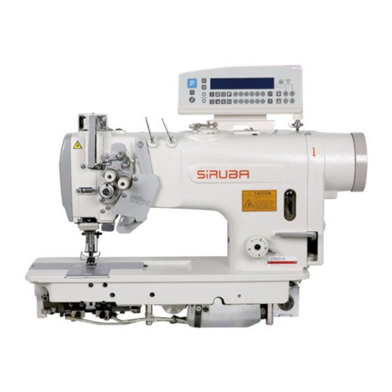
Siruba DT8200 series
Contents
1. Installation Introduction .................................................................... 1
Product specifications ..................................................................... 1
1.1
Interface connection ...................................................................... 1
1.2
2 Operation Panel Instruction. ............................................................. 4
2.1 Operation panel display instruction ............................................... 4
2.2 The operation panel keys of description... .....................................5
3 System parameter setting ................................................................. 9
3.1 Technician mode ........................................................................... 9
3.2 Administrator mode ..................................................................... 14
3.3 Monitoring Mode .......................................................................... 20
3.4 Safety switch warning mode ........................................................ 20
3.5 False alarm mode ........................................................................ 21
4
Special function operating instructions ........................................ 22
4.1 Upper stop position adjust ........................................................... 22
4.2 A key recovery machine manufacturers parameter value ........... 23
4.3 Pedal sensitivity adjustment ........................................................ 23
4.4 Electromagnet performance adjustment ...................................... 24
4.5 Start/ end back tacking sewing mode set .................................... 25
needle ................................................................................................ 26
27
i
Advertisement
Table of Contents

Related Manuals for Siruba DT8200 Series


Summary of Contents for Siruba DT8200 Series
-
Page 1: Table Of Contents
Siruba DT8200 series Contents 1. Installation Introduction ..............1 Product specifications ..............1 Interface connection ..............1 2 Operation Panel Instruction.............. 4 2.1 Operation panel display instruction ..........4 2.2 The operation panel keys of description… ........5 3 System parameter setting ..............9 3.1 Technician mode ................ -
Page 2: Installation Introduction
Siruba DT8200 series Safety Instruction · Please read this manual carefully, also with related manual for the machinery before use the controller. · For installing and operating the controller properly and safely, qualified personnel are required. · Please try to stay away from arc welding equipment, in order to avoid electromagnetic interference and malfunction of the controller. - Page 3 Siruba DT8200 series Fig.1-1 AS series Control Box ①:the motor power supply socket; ②: the pedal socket; ③:the motor encoder socket; ④:the operation panel switch socket socket;⑤:the turn table;⑥:the automatic electromagnet socket; ⑦:the presser foot lifting electromagnet socket; ⑧:the head lamp socket (black);...
- Page 4 Siruba DT8200 series Fig.1-3 Controller interface definition ■ 1.3 Power Connection and Grounding basic parameters Please electrical engineer must do construction to the system grounding engineering. Electricity and put into use, must ensure that the power supply socket AC input has been safe and reliable grounding. System ground is yellow-green line, the line must be connected to the power grid safe reliable grounding protection, to ensure the safe use, and can prevent the abnormal situation.
-
Page 5: Operation Panel Instruction
Siruba DT8200 series 2 Operation Panel Instruction 2.1 Operation panel display instruction According to the operating condition of the system, LCD module of operation panel will display the sewing patterns, various parameters, front / back fixed seam to set the current, and the presser foot, stop needle position, trimming thread, slow up the joint character of the LCD. -
Page 6: The Operation Panel Keys Of Description
Siruba DT8200 series Numeric character Four –segment sewing display (pin number / parameter) Foot lifter after Count needle number trimming Middle stop foot lifter Count piece number Intermediate stops Count display down stop position Intermediate stops Speed mark up stop position... - Page 7 Siruba DT8200 series Description Appearance Name It is called end back tacking function selection keys, every effective press the key once, system will be in accordance with the 11B parameter set none and single end back tacking , double end...
- Page 8 Siruba DT8200 series Description Appearance Name Press this key, LCD icon is lit, show soft start function effectively, then press the icon is off, indicates close soft start Soft start key function. Press this key, LCD icon is lit, show clamp function...
- Page 9 Siruba DT8200 series Description Appearance Name In the multi segment sewing mode, press the key, LCD icon is , suggesting that trigger mode effectively, the pedal can be One-Shot-Sewing key accomplished once the current period of setting needle sewing; then click the icon out, show that multi segment joint triggered off.
-
Page 10: System Parameter Setting
Siruba DT8200 series 3 System parameter setting 3.1 Technician mode 1、Press key and key can modify the technician parameter table. 2、 The LCD will display .Type the password for the technician, the initial password is 0 0 0 0,press the corresponding key and key can change the password value;... - Page 11 Siruba DT8200 series Start and end back tacking type (CD and AB) 0:B->AB->ABAB->none 1:B->none 2:B->AB->none 3:AB->none 4:AB->ABAB->none Corresponding to A/B/C/D pins of ten bit, start and end back 0000- tacking interface under the A/B/C/D digits together constitute the two digit pin number, each section of pin number 1~99 needle.
- Page 12 Siruba DT8200 series Foot lifting position, foot lifting function selection: 0/1 0: without 1:with 1~800 Trimming after, foot lifting delay time(clamp) Run to up needle position after Power on: 0/1 0: no action 1: action Automatically reinforcing functions chose :...
- Page 13 Siruba DT8200 series Stitch counting mode selection: 0: no counting 1: Counting up according to stitch number, after reaching set value then restart. 2: Counting down according to stitch number, after reaching set value then restart. 3: Counting up according to stitch number, after reaching set value ,motor automatically stop, by the reset button set or the P 0~4...
- Page 14 Siruba DT8200 series Corresponding to 1/2/3/4, an electromagnet chopper duty time 0~ selection (0 in MS, 1 in 0.1ms) Corresponding to 5/6/7/8, an electromagnet chopper duty time 0~ selection (0 in MS, 1 in 0.1ms) Counting adjustable switch (gauge needle number and piece 0~1...
-
Page 15: Administrator Mode
Siruba DT8200 series 3.2 Administrator mode 1、Press key and key can modify the administrator parameter table. 2、The LCD will display .Type the password for the administrator, the initial password is 0 0 0 0,press the corresponding key and key can change the password value;... - Page 16 Siruba DT8200 series 4: After upper needle stop position is reached, time delay to the parameter 205 set value[T1] then start trimming, time delay to the parameter 206 set value [T2], most applications are for interlock machines. 5: find the needle position signal started first stop pin stop tangent action.
- Page 17 Siruba DT8200 series 4: needle position signal delay [L1] set the time to looseline, 214 parameters set by the [L2] until the time delay. Under 5: bit signal started loose line first stop pin stop.Then the delay parameter 213 set time [L1] after the 214parameter set loose line time [L2].
- Page 18 Siruba DT8200 series Emergency Stop Mode: 0: Turn off the emergency stop function 0/1/2/3 1: Emergency stop at any position 2: Emergency stop at upper needle stop position 3: Emergency stop at lower needle stop position Continue stitch No. before emergency stop (according to different 0~...
- Page 19 Siruba DT8200 series 0~2000 Oil refill time alarm (hour. 0: function deactivated) 0~4000 Oil alarm, stop operation time (hour. 0: function deactivated) No.1 input definition 25 1 No.1 active input level 0/1 25 2 No.2 input definition Input No.2 active input level 0/1...
- Page 20 Siruba DT8200 series 1~500 No.1 electromagnet fully output time ms 1~100 No.1 electromagnet chopping on time ms(Reserved) 1~100 No.1 electromagnet chopping off time ms(Reserved) 0~ 00 No.1 electromagnet protection time 100ms 1~500 No.2 electromagnet fully output time ms 1~100 No.2 electromagnet chopping on time ms(Reserved) 1~100...
-
Page 21: Monitoring Mode
上海鲍麦克斯电子科技有限公司 AH 系列数控交流伺服系统说明书 3.3 Monitoring Mode key and key press can enter the monitor mode, LCD shown is 2, press the corresponding to key to select parameter number, can be real-time monitoring ofchanges in the corresponding parameters; 3, finally press key, is to return to the normal sewing pattern Description Description... -
Page 22: False Alarm Mode
上海鲍麦克斯电子科技有限公司 AH 系列数控交流伺服系统说明书 3.5 False alarm mode If the system error or warning, please first check the following items: 1, to confirm the connection machine is connected properly; 2, confirm the control and head matches; 3, confirm restore factory is accurate. error meaning solution... -
Page 23: Special Function Operating Instructions
上海鲍麦克斯电子科技有限公司 AH 系列数控交流伺服系统说明书 DSP Read/Write Er r-14 EEPROM failure Motor over-speed Er r-15 protection Turn off the system power, restart the system after 30 seconds, if it still does Er r- not work, please replace the controller and inform the manufacturer. Motor reversion HMI Read/Write Er r-17... -
Page 24: A Key Recovery Machine Manufacturers Parameter Value
上海鲍麦克斯电子科技有限公司 AH 系列数控交流伺服系统说明书 4.2 A key recovery machine manufacturers parameter value If you want to restore the factory parameters, according to the following steps: The first step: first press key, then press key, enter into monitor mode; The default is 024, monitoring parameters. -
Page 25: Electromagnet Performance Adjustment
上海鲍麦克斯电子科技有限公司 AH 系列数控交流伺服系统说明书 3、the parameter settings are required to ensure that (parameter 134) < (parameter 135) < (parameter 136) < (parameter 137) < (parameter 138) < (parameter 139) 4、an be used as the parameter's value through the pedal real-time monitoring of 025 parameters at different positions of the monitoring mode sampling numerical. -
Page 26: Start/ End Back Tacking Sewing Mode Set
上海鲍麦克斯电子科技有限公司 AH 系列数控交流伺服系统说明书 the No. 2 electromagnet set parameter 274~277 is reverse stitching electromagnet set parameters. Parameters of 262 to 4, showed that the No. 3 electromagnets are set to the presser foot lifting electromagnet, the electromagnet is No. 3 set parameter 278~27B is the presser foot lifting electromagnet set parameters. -
Page 27: Start/ End Back Tacking Sewing And Four-Segment Sewing Is Set Long Needle
上海鲍麦克斯电子科技有限公司 AH 系列数控交流伺服系统说明书 single start/end back tacking sewing mode set double start/end back tacking sewing mode set ① ② four start/end back tacking sewing mode set None start/end back tacking sewing mode set ③ ④ By adjusting the 11B parameters, modified back tacking sewing mode. - Page 28 上海鲍麦克斯电子科技有限公司 AH 系列数控交流伺服系统说明书 But if you need to set the number of needles more, can be specified to set the number of needles by modifying 11C parameters and 11D parameters of ten, plus A/B/C/D and E/F/G/H segment is a digit, together constitute the total needle number.
-
Page 29: Operating Panel Count Needle Number / Piece Number Function
上海鲍麦克斯电子科技有限公司 AH 系列数控交流伺服系统说明书 4.7 H-70 operating panel count needle number / piece number function H-70 operating panel contains special count needle number / piece number display module. H-70 operating panel system parameter is set the way and the H-43 panel is the same The first step, press key, then press key, the LCD... - Page 30 上海鲍麦克斯电子科技有限公司 AH 系列数控交流伺服系统说明书 At this time , press counting key can switch count needle number and piece function in the show . The system default settings count fast modifying function. Adjustable parameter 158, modified to 1 to disable this feature, the default is 0 open this function.
Need help?
Do you have a question about the DT8200 Series and is the answer not in the manual?
Questions and answers