Table of Contents
Advertisement
Quick Links
Advertisement
Table of Contents

Related Manuals for DFI SD100-H110/Q170


Summary of Contents for DFI SD100-H110/Q170
- Page 1 SD100-H110/Q170 Mini-ITX Industrial Motherboard User’s Manual A41850952...
-
Page 2: Copyright
Copyright FCC and DOC Statement on Class B This publication contains information that is protected by copyright. No part of it may be re- This equipment has been tested and found to comply with the limits for a Class B digital produced in any form or by any means or used to make any transformation/adaptation without device, pursuant to Part 15 of the FCC rules. -
Page 3: Table Of Contents
Table of Contents Audio ......................23 I/O Connectors ................... 24 SATA (Serial ATA) Connectors ..............24 Digital I/O Connector .................. 24 Digital I/O Power Connector ................ 24 Copyright ......................2 Cooling Fan Connectors................25 Power Connectors ..................25 Trademarks ......................2 LVDS LCD Panel Connector ................. -
Page 4: Warranty
Warranty Static Electricity Precautions 1. Warranty does not cover damages or failures that arised from misuse of the product, in- It is quite easy to inadvertently damage your PC, system board, components or devices even ability to use the product, unauthorized replacement or alteration of components and prod- before installing them in your system unit. -
Page 5: About The Package
The package contains the following items. If any of these items are missing or damaged, please contact your dealer or sales representative for assistance. • One SD100-H110/Q170 motherboard • One COM port cable (Length: 250mm, 1 x COM port) •... -
Page 6: Chapter 1 - Introduction
Chapter 1 Chapter 1 - Introduction REAR I/O Display 1 x VGA Specifications 1 x DVI-I (DVI-D signal) 1 x DP++ SYSTEM Processor 7th Generation Intel ® Core™ Processors, LGA 1151 Socket Audio 1 x Line-in (available upon request) Intel ®... -
Page 7: Features
Chapter 1 Features • Wake-On-LAN • Watchdog Timer This feature allows the network to remotely wake up a Soft Power Down (Soft-Off) PC. It is supported via the onboard LAN port or via a PCI LAN card that uses the PCI PME (Power Man- The Watchdog Timer function allows your application to regularly “clear”... - Page 8 Chapter 1 • Power Failure Recovery When power returns after an AC power failure, you may choose to either power-on the system manually or let the system power-on automatically. • USB The system board supports the new USB 3.0. It is capable of running at a maximum transmis- sion speed of up to 5 Gbit/s (625 MB/s) and is faster than USB 2.0 (480 Mbit/s, or 60 MB/s) and USB 1.1 (12Mb/s).
-
Page 9: Chapter 2 - Hardware Installation
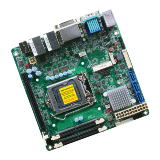
Chapter 2 Chapter 2 - Hardware Installation Important: Board Layout Electrostatic discharge (ESD) can damage your board, processor, disk drives, add-in boards, and other components. Perform installation procedures at an ESD workstation only. If such a station is not available, you can provide some ESD protection by wear- ing an antistatic wrist strap and attaching it to a metal part of the system chassis. -
Page 10: Installing The Dimm Module
Chapter 2 Installing the DIMM Module The system board supports the following memory interface. Note: Single Channel (SC) The system board used in the following illustrations may not resemble the actual Data will be accessed in chunks of 64 bits (8B) from the memory channels. board. -
Page 11: Cpu
Chapter 2 6. Grasping the module by its edges, position the module above the socket with the “notch” in the module aligned with the “key” on the socket. The keying mechanism ensures the module can be plugged into the socket in only one way. The system board is equipped with a surface mount LGA 1151 socket. -
Page 12: Installing The Cpu
Chapter 2 Load lever Installing the CPU 5. Lifting the load lever will at the same time lift the load plate. 1. Make sure the PC and all other peripheral devices connected to it has been powered down. Lift the load lever up to 2. - Page 13 Chapter 2 7. Insert the CPU into the 8. Close the load plate then socket. The gold triangular push the load lever down. mark on the CPU must align with the corner of While closing the load Retention knob the CPU socket shown on plate, make sure the front the photo.
-
Page 14: Installing The Fan And Heat Sink
Chapter 2 Installing the Fan and Heat Sink 4. Rotate each screw that are diagonally across the heat sink. Perform the same The CPU must be kept cool by using a CPU fan with heat sink. Without sufficient air circula- procedure for the other tion across the CPU and heat sink, the CPU will overheat damaging both the CPU and system screws. -
Page 15: Jumper Settings
Chapter 2 Jumper Settings Backlight Power Select Clear CMOS Data 1-2 On: 1-2 On: Normal (default) +3.3V (default) 2-3 On: 2-3 On: Clear CMOS Data If you encounter the followings, JP3 is used to select the power level of backlight brightness control: +3.3V (default) or +5V. a) CMOS data becomes corrupted. -
Page 16: Com1/Com2 Rs232/Power Select
Chapter 2 COM1/COM2 RS232/Power Select JP6 (COM 1) 1-3 (RI-), 2-4 (DCD-) On: 3-5 (+5V), 4-6 (+12V) On: (COM 1) RS232 (default) RS232 with power JP8 (COM 2) (COM 2) 2 4 6 2 4 6 1 3 5 1 3 5 1-3 (RI-), 2-4 (DCD-) On: 3-5 (+5V), 4-6 (+12V) On: RS232 (default) -
Page 17: Auto Power-On Select
Chapter 2 Mini PCIe Signal Select Auto Power-on Select 1-2 On: Power-on via power button (default) 1-2 On: Mini PCIe (default) 2-3 On: Power-on via AC power 2-3 On: mSATA (SD100-Q170 Only) JP5 is used to select the method of powering on the system. If you want the system to power on whenever AC power comes in, set JP5 pins 2 and 3 to On. -
Page 18: Lcd/Inverter Power Select
Chapter 2 LCD/Inverter Power Select Panel Power Select 1 3 5 1-2 On: +12V (default) 1-2 On: +12V 2-3 On: +5V 1 3 5 3-4 On: +5V 1 3 5 5-6 On: +3.3V (default) JP7 is used to select the power supplied with the LCD panel. JP2 is used to select the power level of LVDS LCD inverter connector. -
Page 19: Rear Panel I/O Ports
Chapter 2 Rear Panel I/O Ports PS/2 Keyboard/Mouse Port PS/2 Keyboard/Mouse DVI-I (DVI-D signal) LAN 1 LAN 2 PS/2 KB/MS COM 1 Line-in (optional) Line-out Mic-in USB 2.0*2 DP++ USB 3.0*4 The rear panel I/O ports consist of the following: •... -
Page 20: Rj45 Lan Ports
Chapter 2 RJ45 LAN Ports USB Ports LAN 2 LAN 1 USB 2.0 LAN 1 LAN 2 USB 7-8 USB 11-12 (Only for SD100-Q170) USB 6 USB 5 USB 2.0 Features USB 2 USB 1 SD100-H110 : USB 3.0 • Intel I211AT PCIe ®... -
Page 21: Graphics Interfaces
Chapter 2 Graphics Interfaces BIOS Setting Configure these onboard USB devices in the Advanced menu (“USB Configuration” submenu) The display ports consist of the following: of the BIOS. Refer to the chapter 3 for more information. • 1 VGA port Driver Installation •... -
Page 22: Com (Serial) Ports
Chapter 2 COM (Serial) Ports COM 2 N.C. N.C. 1 2 3 4 5 RTS- N.C. N.C. CTS- N.C. N.C. N.C. DSR- N.C. TXD- DTR- TXD+ N.C. N.C. DCD- RXD- RXD+ DATA- DATA+ 6 7 8 9 RS422 RS232 RS485 Full Duplex COM 1: RS232 COM 2: RS232/422/485... -
Page 23: Audio
Chapter 2 Audio Rear Audio Line-in (optional) Line-out Mic-in Rear Audio The system board is equipped with 2 audio jacks (Line-out and Mic-in). Line-in jack is available upon request. A jack is a one-hole connecting interface for inserting a plug. •... -
Page 24: I/O Connectors
Chapter 2 I/O Connectors Digital I/O Connector Digital I/O Power Connector SATA (Serial ATA) Connectors SATA 3.0 6Gb/s SATA 0 SATA 2 SATA 3 Digital I/O Digital I/O Power +12V Ground 5VSB Features The 8-bit Digital I/O connector provides powering-on function to external devices that are con- •... -
Page 25: Cooling Fan Connectors
Chapter 2 Cooling Fan Connectors Power Connectors ATX power 12 24 +3.3V +12V Ground +12V +5VSB CPU Fan CTRL PWR_OK PS_ON# +3.3V -12V System Fan 2 +3.3V +3.3V ystem Fan 1 +12V Power FAN IN Ground Ground +12V +12V Ground The fan connectors are used to connect cooling fans. -
Page 26: Lvds Lcd Panel Connector
Configure the LCD panel in the Advanced menu (“Video Configuration” sub- Panel Power Panel Power menu) of the BIOS. Refer to the chapter 3 for more information. Note: DFI board's LVDS connector: Hirose DF13-40DP-1.25V(91)/40P/1.25mm; cable side connector: Hirose DF13-40DS-1.25C. Chapter 2 Hardware Installation www.dfi .com... -
Page 27: Chassis Intrusion Connector
Chapter 2 Chassis Intrusion Connector Front Panel Connector Front Panel PWR-LED HD-LED ATX-SW RESET Signal Chassis Intrusion Ground HD-LED - Hard Drive LED This LED will light when the hard drive is being accessed. The board supports the chassis intrusion detection function. Connect the chassis intrusion sensor cable from the chassis to this connector. -
Page 28: Smbus Connector
Chapter 2 SMBus Connector S/PDIF Connector 3V3DU SMBUS_CLK SMBUS_Data SMBus SMBUS_Alert S/PDIF The SMBus (System Management Bus) connector is used to connect SMBus devices. It is a The S/PDIF connector is used to connect an external S/PDIF port. Your S/PDIF port may be multiple device bus that allows multiple chips to connect to the same bus and enable each one mounted on a card-edge bracket. -
Page 29: Lpc Connector
Connecting the EXT-RS232/RS485 Card to the Motherboard With DFI’s proprietary technology, SD100-H110/Q170 supports two extension modules for ad- ditional four COM ports. The EXT-RS232/RS485 card is connected to SD100-H110/Q170 via the LPC connector. The illustrations below guide you how to connect the extension module to the motherboard. -
Page 30: Expansion Slots
Chapter 2 Expansion Slots Battery Mini PCI Express Battery Connector +3.3V PCI Express x16 Mini PCI Express Slot The Mini PCIe socket is used to install a Mini PCIe card. Mini PCIe card is a small form factor PCI card with the same signal protocol, electrical definitions, and configuration definitions as the conventional PCI. -
Page 31: Chapter 3 - Bios Setup
“Press DEL to run setup” will appear on the screen. If the message that field and press <Enter>. disappears before you respond, restart the system or press the “Reset” button. You may also restart the system by pressing the <Ctrl> <Alt> and <Del> keys simultaneously. Chapter 3 BIOS Setup www.dfi.com... -
Page 32: Insyde Bios Setup Utility (For Intel 6Th Generation Cpu)
SD100-H110/Q170, we support both Intel 6th and 7th generation CPU. If your BIOS indicates that it supports 6th and 7th generation CPU on main menu, please refer page 43~57. For BIOS supporting 6th generation CPU only, please refer page 32~42. - Page 33 S0 State The system is in working state. the processor’s power, temperature, and specification are within the limits of TDP. S5 State The system is in soft-off state. Chapter 3 BIOS Setup www.dfi.com...
- Page 34 LCD Panel Type <1024x768> LCD+DVI LCD+VGA LCD+DP DVI+LCD DVI+VGA DVI+DP VGA+LCD VGA+DVI VGA+DP DP+LCD DP+DVI DP+VGA Help ↑/↓ Select Item F5/F6 Change Values Setup Defaults Exit ←/→ Select Item Enter Select SubMenu Save and Exit Chapter 3 BIOS Setup www.dfi.com...
- Page 35 RAID Mode (SD100-Q170 only) This option allows you to create RAID or Intel Matrix Storage configuration on Serial ATA devices. Serial ATA Port 0, 1, 2, and 3 Enable or disable each serial ATA port. Chapter 3 BIOS Setup www.dfi.com...
- Page 36 PCIe Speed Select the speed of the PCI Express Root Port: Auto, Gen1, Gen2 or Gen3. Help ↑/↓ Select Item F5/F6 Change Values Setup Defaults Exit ←/→ Select Item Enter Select SubMenu Save and Exit Chapter 3 BIOS Setup www.dfi.com...
- Page 37 1, the system or CPU fan should be turned on and operate at the designated speed. The range is from 0-127 Fan Speed Count 1 to Fan Speed Count 4 Set the fan speed. The range is from 0 (fan stop)-100% (full speed). Chapter 3 BIOS Setup www.dfi.com...
- Page 38 Set the AC power loss to Always off or Always on. When set to Always off, the sys- tem’s status will be power-off after an AC power loss event. When set to Always on, the system’s status will be power-on after an AC power loss event. Chapter 3 BIOS Setup www.dfi.com...
-
Page 39: Security
Set the master password for all HDDs. The length of password must be greater than 1 character and less than or equal to 32 characters. This item will be displayed when the security mode of HDD is not Lock. Chapter 3 BIOS Setup www.dfi.com... - Page 40 32 characters. When the secutiry mode is Lock, input master HDD password to unlock the HDD. Master HDD password is valid when HDD password is set. Press “Enter” to set a new password. Chapter 3 BIOS Setup www.dfi.com...
-
Page 41: Boot
Disables or enables Preboot eXecution Environment (PXE) boot to LAN. Use + and - keys to arrange the priority of the listed boot devices. USB Boot Enable or disable the booting to USB boot devices. Chapter 3 BIOS Setup www.dfi.com... -
Page 42: Exit
Select this field and press <Enter> to exit BIO setup and save your changes. Load Optimal Defaults Select this field and press <Enter> to load the optimal defaults. Discard Changes Select this field and press <Enter>to exit the BIOS setup without saving your changes. Chapter 3 BIOS Setup www.dfi.com... -
Page 43: Insyde Bios Setup Utility (For Intel 6/7Th Generation Cpu)
The Main menu is the first screen that you will see when you enter the BIOS Setup Utility. For SD100-H110/Q170, we support both Intel 6th and 7th generation CPU. If your BIOS indicates that it supports 6th and 7th generation CPU on main menu, please refer page 43~57. For BIOS supporting 6th generation CPU only, please refer page 32~42. - Page 44 Automatically power the system on at a particular time every day from the Real-time clock battery. Wake up time When Wake On RTC is set to enabled, specify the wake up time of the day: <hour> (00~23), <minute> (00~59), <second> (00~59). Chapter 3 BIOS Setup www.dfi.com...
- Page 45 When disabled, only one thread per enabled core is enabled. DVI+VGA DP1+DVI DP1+VGA VGA+DVI VGA+DP1 Help ↑/↓ Select Item F5/F6 Change Values Setup Defaults Exit ←/→ Select Item Enter Select SubMenu Save and Exit Chapter 3 BIOS Setup www.dfi.com...
- Page 46 Select the type of LCD panel connected to the system’s LCD connector: 800x480, 800x600, 1024x768, 1366x768, 1280x1024 or 1920x1080. Please check the specifica- tions of your LCD monitor. Backlight Type Select Backlight Type: Normal+PWM Mode, Normal+DC Mode, Invert+PWM Mode or Invert+DC Mode. Chapter 3 BIOS Setup www.dfi.com...
- Page 47 This option allows you to create RAID or Intel Matrix Storage configuration on Serial ATA devices. Serial ATA Port 0, 1, 2, 3 and Hot Plug These fields are used to enable or disable the serial ATA port and its hot plug. Chapter 3 BIOS Setup www.dfi.com...
- Page 48 This field is used to enable or disable the PCI Express Root Port. PCIe Speed Select the speed of the PCI Express Root Port: Auto, Gen1, Gen2 or Gen3. Hot Plug This field is used to enable or disable the PCI Express Hot Plug. Chapter 3 BIOS Setup www.dfi.com...
- Page 49 PCI Express Root Port This field is used to enable or disable the PCI Express Root Port 4 settings. PCIe Speed Select the speed of the PCI Express Root Port: Auto, Gen1, Gen2 or Gen3. Chapter 3 BIOS Setup www.dfi.com...
- Page 50 This field is used to enable or disable the flash ME region. Intel AMT Support This field is used to enable or disable Intel Active Management Technology ® BIOS Extension. Un-Configure ME This field is used to enable or disable un-figuring ME without password. Chapter 3 BIOS Setup www.dfi.com...
- Page 51 UEFI Device Manager UEFI Device Manager Exit BIOS Setup Utility and launch Device Manager !! [OK] Help ↑/↓ Select Item F5/F6 Change Values Setup Defaults Exit ←/→ Select Item Enter Select SubMenu Save and Exit Chapter 3 BIOS Setup www.dfi.com...
- Page 52 1, the system or CPU fan should be turned on and operate at the designated speed. The range is from 0-127 Fan Speed Count 1 to Fan Speed Count 4 Set the fan speed. The range is from 1-100% (full speed). Chapter 3 BIOS Setup www.dfi.com...
- Page 53 Choose RS232, RS422 or RS485 (Peer-to-Peer) for the serial port type for COM port 2. Enable or disable the watchdog function. A counter will appear if you select to enable WDT. Input any value between 1 to 255 seconds. Case Open Enable or disable the case open detection function. Chapter 3 BIOS Setup www.dfi.com...
- Page 54 Select data bits: 7 bits or 8 bits. Parity Select parity bits: none, even or odd. Stop Bits Select stop bits: 1 bit or 2 bits. Flow Control Select flow control type: none, RTS/CTS or XON/XOFF. Chapter 3 BIOS Setup www.dfi.com...
- Page 55 This field is to enable or disable to use global setting. When enabled the global set- ting, setting of the COM port will be the same as those in Console Redirection section. When disabled the global setting, setting of the COM port can be configured indepen- dently in this section. Chapter 3 BIOS Setup www.dfi.com...
-
Page 56: Security
Please refer to Chapter 5 ˗ RAID (SD100-Q170 only) for more information. Network Stack This field is used to enable or disable network stack. PXE Boot capability Disabled : Suppoort Network Stack UEFI PXE : IPv4/IPv6 Legacy : Legacy PXE OPROM only Chapter 3 BIOS Setup www.dfi.com... -
Page 57: Exit
Select this option to save BIOS configuration settings to a USB flash device. Restore Setting from file This field will appear only when a USB flash device is detected. Select this field to restore setting from the USB flash device. Chapter 3 BIOS Setup www.dfi.com... -
Page 58: Updaing The Bios
When the BIOS IC needs to be replaced, you have to populate it properly onto the system board after the EEPROM programmer has been burned and follow the technical person's instructions to confirm that the MAC address should be burned or not. Chapter 3 BIOS Setup www.dfi.com... -
Page 59: Chapter 4 - Supported Software
You may acquire the software from your sales representa- tives, from an optional DVD included in the shipment, or from the website download page at https://www.dfi.com/DownloadCenter. Intel Chipset Software Installation Utility The Intel Chipset Software Installation Utility is used for updating Windows INF files so that ®... - Page 60 Chapter 4 Intel Graphics Drivers 3. Go through the readme document for system re- quirements and installation To install the driver, download “Graphics Driver” zip file at our website. tips then click “Next”. 1. Setup is now ready to install the graphics driver. Click “Next”.
- Page 61 Chapter 4 Audio Drivers Intel LAN Drivers To install the driver, download “Audio Driver” zip file at our website. To install the driver, download “LAN Driver” zip file at our website. 1. Setup is ready to install the 1. Setup is ready to install the driver.
- Page 62 Chapter 4 Kernel Mode Driver Framework (For Windows 7 only) 4. Click “Install” to begin the installation. To install the driver, download “KMDF” zip file at our website. 1. Click “Yes” to install the update. 2. The update is installed 5.
- Page 63 Chapter 4 Intel Management Engine Interface Drivers 3. Click “Next” to install to the default folder, or click “Change” to choose another To install the driver, download “MEI” zip file at our website. destination folder. 1. Setup is ready to install the driver.
- Page 64 Chapter 4 HW Utility 3. Read the license agreement then click “I accept the terms in the license agreement”. HW Utility provides information about the board, Watchdog and DIO. To access the utility, Click “Next”. download “HW Utility” zip file at our website. Note: If you are using Windows 7, you need to access the operating system as an administrator to be able to install the utility.
- Page 65 Chapter 4 6. After completing installa- The HW Utility icon will appear on the desktop. Double-click the icon to open the utility. tion, click “Finish”. Information HW Health Chapter 4 Supported Software www.dfi .com...
- Page 66 Chapter 4 HW Health Set Backlight WatchDog Chapter 4 Supported Software www.dfi .com...
- Page 67 Chapter 4 Intel USB 3.0 Drivers (For Windows 7 and Windows 8.1) 3. Click “Next”. To install the driver, download “USB 3.0 Driver” zip file at our website. 1. Setup is ready to install the driver. Click “Next”. 4. Setup is currently installing the driver.
- Page 68 Chapter 4 IO Driver 3. Go through the readme docu- ment for system requirements and installation tips then click “Next”. To install the driver, download “SIO Driver” zip file at our website. 1. Setup is ready to install the driver. Click “Next”.
- Page 69 Chapter 4 Microsoft Framework 4.5.2 (For Windows 7) 5. Setup is now installing the driver. Note: Before installing Microsoft Framework 4.5.2, make sure you have updated your Windows 7 operating system to Service Pack 3. To install the driver, download “DotNETFx45” zip file at our website. 1.
- Page 70 Chapter 4 Intel Rapid Storage Technology 3. Setup is now installing the driver. The Intel Rapid Storage Technology is a utility that allows you to monitor the current status of the SATA drives. It enables enhanced performance and power management for the storage subsystem.
- Page 71 Chapter 4 Adobe Acrobat Reader 9.3 4. Click “Finish” to exit installation. To install the reader, click “Adobe Acrobat Reader 9.3” on the main menu. 1. Click “Next” to install or click “Change Destination Folder” to select another folder. 2. Click “Install” to begin instal- lation.
-
Page 72: Chapter 5 - Raid (Sd100-Q170 Only)
Chapter 5 Chapter 5 - RAID (SD100-Q170 Only) Settings The system board allows configuring RAID on Serial ATA drives. It supports RAID 0 and RAID To enable the RAID function, the following settings are required. RAID Levels 1. Connect the Serial ATA drives. 2. - Page 73 Chapter 5 Step 3: Create a RAID Volume Step 3-1: Create a RAID Volume if the boot type is UEFI 1. When the Intel RST option ROM status screen displays during POST, press <Ctrl> and If the boot type is set to UEFI, RAID volume creation will be different. Please use the following ®...
- Page 74 Chapter 5 Step 4: Install the Intel Rapid Storage Technology Utility 4. Go through the readme document to view system requirements and installa- The Intel Rapid Storage Technology Utility can be installed from within Windows. It allows tion information then click RAID volume management (create, delete, migrate) from within the operating system.
- Page 75 Chapter 5 7. Click “Yes, I want to restart this computer now” to complete the installation and then click “Finish”. Chapter 5 RAID www.dfi .com...
-
Page 76: Chapter 6 - Intel Amt Settings (Sd100-Q170 Only)
Chapter 6 Chapter 6 - Intel AMT Settings (SD100-Q170 Only) Enable Intel AMT in the Insyde BIOS ® Overview 1. Power-on the system then press <Del> to enter the main menu of the Insyde BIOS. Intel Active Management Technology (Intel AMT) combines hardware and software solution to ®... - Page 77 Chapter 6 Enable Intel AMT in the Intel Management 4. In the Exit menu, select Exit Saving Changes then select Yes and press Enter. ® ® Engine BIOS Extension (MEBX) Screen InsydeH20 Setup Utility Rev. 5.0 1. After the system reboots, press <Del> to enter the main menu of the Insyde BIOS. Main Advanced Security...
- Page 78 Chapter 6 4. Select MEBx Login and press Enter. You will be prompted for a password. The default 6. You will be asked to verify the new password. Enter the same new password in the space password is “admin”. Enter the default password in the space provided under Intel(R) ME provided under Verify Password then press Enter.
- Page 79 Chapter 6 8. If you want to change ME password, select Change ME Password then press Enter. 10. You will be asked to verify the new password. Enter the same new password in the space Enter the current password in the space provided under Intel(R) ME Password then press provided under Verify Password then press Enter.
- Page 80 Chapter 6 Press Esc until you return to the Main Menu. Select Intel(R) AMT Configuration then In the Intel(R) AMT Configuration menu, select SOL/Storage Redirection/KVM press Enter. then press Enter. Intel(R) Management Engine BIOS Extension v11.0.0.0010/Intel(R) ME v11.8.50.3399 Intel(R) Management Engine BIOS Extension v11.0.0.0010/Intel(R) ME v11.8.50.3399 Copyright(C) 2003-16 Intel Corporation.
- Page 81 Chapter 6 Select SOL then press Enter. Select Enabled or Disabled then press Enter. Select KVM Feature Selection then press Enter. Select Enabled or Disabled then press Enter. Intel(R) Management Engine BIOS Extension v11.0.0.0010/Intel(R) ME v11.8.50.3399 Intel(R) Management Engine BIOS Extension v11.0.0.0010/Intel(R) ME v11.8.50.3399 Copyright(C) 2003-16 Intel Corporation.
- Page 82 Chapter 6 In the User Consent menu, select User Opt-in then press Enter. Select NONE or KVM Press Esc until you return to the Intel(R) AMT Configuration menu. Select Password or ALL then press Enter. Policy then press Enter. You may choose to use a password only during setup and configuration or to use a pass- word anytime the system is being accessed.
- Page 83 Chapter 6 In the Intel(R) ME Network Setup menu, select Intel(R) ME Network Name Set- Select Domain Name then press Enter. Enter the computer’s domain name then press tings then press Enter. Enter. Intel(R) Management Engine BIOS Extension v11.0.0.0010/Intel(R) ME v11.8.50.3399 Intel(R) Management Engine BIOS Extension v11.0.0.0010/Intel(R) ME v11.8.50.3399 Copyright(C) 2003-16 Intel Corporation.
- Page 84 Chapter 6 Select Dynamic DNS Update then press Enter. Select Enabled or Disabled then press Select TTL then press Enter. Enter value then press Enter. Enter. If Dynamic DNS Update is set to Enabled, Periodic Update Interval and TTL fields will show up. Intel(R) Management Engine BIOS Extension v11.0.0.0010/Intel(R) ME v11.8.50.3399 Intel(R) Management Engine BIOS Extension v11.0.0.0010/Intel(R) ME v11.8.50.3399 Copyright(C) 2003-16 Intel Corporation.
- Page 85 Chapter 6 In the Wired LAN IPV4 Configuration menu, select DHCP Mode then press Enter. Select Subnet Mask Address then press Enter. Enter address then press Enter. Select Enabled or Disabled then press Enter. If set to Disabled, IPV4 Address, Subnet Mask Address, Default Gateway Address, Preferred DNS Address and Alternate DNS Address will show up.
- Page 86 Chapter 6 Select Preferred DNS Address then press Enter. Enter address then press Enter. Press Esc until you return to the Intel(R) AMT Configuration menu. If you want to activate the current network settings and open the ME network inferface, select Activate Network Access, press Enter, then press Y.
- Page 87 Chapter 6 In the Intel(R) AMT Configuration menu, select Remote Setup And Configuration In the Intel(R) Remote Setup And Configuration menu, select Provisioning Re- then press Enter. cord then press Enter. Intel(R) Management Engine BIOS Extension v11.0.0.0010/Intel(R) ME v11.8.50.3399 Intel(R) Management Engine BIOS Extension v11.0.0.0010Intel(R) ME v11.8.50.3399 Copyright(C) 2003-16 Intel Corporation.
- Page 88 Chapter 6 In the Intel(R) Remote Setup And Configuration menu, select Provisioning Press Esc until you return to the Intel(R) Remote Setup And Configuration menu. Server FQDN then press Enter. Enter the FQDN then press Enter. Select TLS PKI then press Enter. Select Remote Configuration ** then press Enter. Select Enabled or Disabled then press Enter.
- Page 89 Chapter 6 In the Intel(R) Remote Configuration menu, select Manage Hashes then press In the Intel(R) AMT Power Control menu, select Idle Timeout then press Enter. Enter. Select the hash name then press Insert to enter custom hash certificate name, Enter the timeout value and press Enter.
-
Page 90: Appendix A - Troubleshooting
Appendix A Appendix A - Troubleshooting Checklist The picture seems to be constantly moving. Troubleshooting Checklist 1. The monitor has lost its vertical sync. Adjust the monitor’s vertical sync. 2. Move away any objects, such as another monitor or fan, that may be creating a magnetic This chapter of the manual is designed to help you with problems that you may encounter field around the display. - Page 91 Appendix A Hard Drive System Board 1. Make sure the add-in card is seated securely in the expansion slot. If the add-in card is Hard disk failure. loose, power off the system, re-install the card and power up the system. 1.
Need help?
Do you have a question about the SD100-H110/Q170 and is the answer not in the manual?
Questions and answers