Table of Contents
Advertisement
Quick Links
Advertisement
Table of Contents

Related Manuals for DFI SD630-H110-000G


Summary of Contents for DFI SD630-H110-000G
- Page 1 SD630-H110 ATX Industrial Motherboard User’s Manual A-397-M-2003...
-
Page 2: Copyright
Copyright FCC and DOC Statement on Class B This publication contains information that is protected by copyright. No part of it may be re- This equipment has been tested and found to comply with the limits for a Class B digital produced in any form or by any means or used to make any transformation/adaptation without device, pursuant to Part 15 of the FCC rules. -
Page 3: Table Of Contents
Table of Contents Power Connectors .................23 Chassis Intrusion Connector ..............24 Front Panel Connector ................24 Copyright ................2 Standby Power LED ................25 Expansion Slots ..................25 S/PDIF Connector ..................26 Trademarks ................2 Battery ....................26 Chapter 3 - BIOS Setup ..........27 FCC and DOC Statement on Class B ......2 Main ....................28 Advanced ....................28 Warranty ................ -
Page 4: Warranty
Warranty Static Electricity Precautions 1. Warranty does not cover damages or failures that arised from misuse of the product, It is quite easy to inadvertently damage your PC, system board, components or devices even inability to use the product, unauthorized replacement or alteration of components and before installing them in your system unit. -
Page 5: About The Package
About the Package The package contains the following items. If any of these items are missing or damaged, please contact your dealer or sales representative for assistance. • One SD630-H110 motherboard • One COM port cable (Length: 400mm, 2 x COM ports) •... -
Page 6: Chapter 1 - Introduction
4 x USB 3.0, 2 x USB 2.0 Height PCB: 1.6mm Serial 1 x RS-232/422/485 (RS-232 with power) (DB-9) Top Side: 31.47mm Bottom Side: 4.40mm PS/2 1 x PS/2 (mini-DIN-6) CERTIFICATIONS CE, FCC Class B, RoHS Chapter 1 Introduction www.dfi.com... -
Page 7: Features
® operating session into RAM (Random Access Memory) when it powers-off. • Audio The Realtek ALC888S-VD2-GR audio codec provides 5.1-channel High Definition audio output. Important: The 5V_standby power source of your power supply must support ≥720mA. Chapter 1 Introduction www.dfi.com... - Page 8 • Wake-On-PS/2 This function allows you to use the PS/2 keyboard or PS/2 mouse to power-on the system. Important: • The 5V_standby power source of your power supply must support ≥720mA. • USB The system board supports the new USB 3.0. It is capable of running at a maximum transmis- sion speed of up to 5 Gbit/s (625 MB/s) and is faster than USB 2.0 (480 Mbit/s, or 60 MB/s) and USB 1.1 (12Mb/s).
-
Page 9: Chapter 2 - Hardware Installation
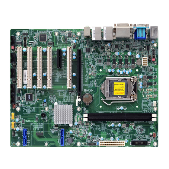
Chapter 2 - Hardware Installation Important: Board Layout Electrostatic discharge (ESD) can damage your board, processor, disk drives, add-in boards, and other components. Perform installation procedures at an ESD workstation System Fan 1 only. If such a station is not available, you can provide some ESD protection by wear- PS/2 KB/MS CPU Fan USB 6... -
Page 10: Installing The Dimm Module
Installing the DIMM Module The system board supports the following memory interface. Single Channel (SC) Note: The system board used in the following illustrations may not resemble the actual Data will be accessed in chunks of 64 bits (8B) from the memory channels. board. -
Page 11: Cpu
6. Grasping the module by its edges, position the module above the socket with the “notch” in the module aligned with the “key” on the socket. The keying mechanism ensures the module can be plugged into the socket in only one way. The system board is equipped with a surface mount LGA 1151 socket. -
Page 12: Installing The Cpu
Installing the CPU Load lever 5. Lifting the load lever will at the same time lift the load plate. 1. Make sure the PC and all other peripheral devices connected to it has been powered down. Lift the load lever up to 2. - Page 13 7. Insert the CPU into the 8. Close the load plate then socket. The gold triangular push the load lever down. mark on the CPU must While closing the load align with the corner of the CPU socket shown on plate, make sure the front Retention knob the photo.
-
Page 14: Installing The Fan And Heat Sink
Installing the Fan and Heat Sink 4. Rotate each push-pin ac- cording to the direction of the arrow shown on top of The CPU must be kept cool by using a CPU fan with heat sink. Without sufficient air circula- the pin. -
Page 15: Jumper Settings
Jumper Settings Clear CMOS Data 1-2 On: Normal (default) 2-3 On: Clear CMOS Data If you encounter the followings, a) CMOS data becomes corrupted. b) You forgot the supervisor or user password. you can reconfigure the system with the default values stored in the ROM BIOS. To load the default values stored in the ROM BIOS, please follow the steps below. -
Page 16: Com1/Com2 Rs232/422/485 Select
COM1/COM2 RS232/422/485 Select JP5 (COM 1)/JP1 (COM 2) 2 4 6 2 4 6 2 4 6 COM 1 1 3 5 1 3 5 1 3 5 1-2 On: 3-4 On: 5-6 On: RS232 (default) RS422 Full Duplex RS485 JP6/JP7 (COM 1) 2 4 6 2 4 6... -
Page 17: Com1/Com2 Rs232/Power Select
COM1/COM2 RS232/Power Select USB Power Select COM 1 JP15 JP12 1-2 On: 5VDU (default) JP11 2-3 On: 5V COM 2 JP13 JP14 JP8 (for COM 1) and JP4 (for COM 2) are used to configure Serial COM ports to pure RS232 The power of the USB connectors’... -
Page 18: Rear Panel I/O Ports
Rear Panel I/O Ports PS/2 Keyboard/Mouse Port PS/2 Keyboard/Mouse DVI-I (DVI-D Signal) COM 1 LAN 2 LAN 1 PS/2 KB/MS Line-out USB 2.0 Mic-in/ Center+Subwoofer HDMI USB 3.0 The rear panel I/O ports consist of the following: • 1 PS/2 Keyboard/Mouse port •... -
Page 19: Com (Serial) Ports
COM (Serial) Ports Graphics Interfaces The display ports consist of the following: • 1 DVI-I(DVI-D signal) port • 1 HDMI port COM 1 • 1 VGA port COM 1: RS232/422/485 DVI-I (DVI-D signal) HDMI COM 3 COM 5 COM 2 COM 4 COM 6 VGA Port... -
Page 20: Rj45 Lan Ports
RJ45 LAN Ports USB Ports USB 6 USB 5 USB 2.0 LAN 2 LAN 1 LAN 2 USB 2 USB 4 LAN 1 USB 3 USB 1 USB 3.0 Features USB 7-8 USB 9-10 USB 2.0 • Intel I211AT PCI Express Gigabit Ethernet controller ®... -
Page 21: Audio
Audio Wake-On-USB Keyboard/Mouse The Wake-On-USB Keyboard/Mouse function allows you to use a USB keyboard or USB mouse to wake up a system from the S3 (STR - Suspend To RAM) state. To use this function: Rear Audio Important: If you are using the Wake-On-USB Keyboard/Mouse function for 2 USB ports, the Line-out +5V_standby power source of your power supply must support ≥1.5A. -
Page 22: I/O Connectors
I/O Connectors Digital I/O Connector SATA (Serial ATA) Connectors Digital I/O SATA 0 SATA 1 The 8-bit Digital I/O connector provides powering-on function to external devices that are con- SATA 2 SATA 3 nected to these connectors. Digital I/O Connector Features Pins Pin Assignment... -
Page 23: Power Connectors
Cooling Fan Connectors Power Connectors Ground CPU Fan +12V Power Ground Speed Control Power System Fan 1 +12V 12 24 Sense +3.3V power +12V +12V +5VSB PWR_OK PS_ON# +3.3V -12V +3.3V +3.3V System Fan 2 Use a power supply that complies with the ATX12V Power Supply Design Guide Version 1.1. These fan connectors are used to connect cooling fans. -
Page 24: Chassis Intrusion Connector
Chassis Intrusion Connector Front Panel Connector Front PWR-LED Panel HDD-LED ATX-SW RESET-SW Chassis Intrusion Signal Ground HDD-LED - HDD LED This LED will light when the hard drive is being accessed. RESET SW - Reset Switch The board supports the chassis intrusion detection function. Connect the chassis intrusion This switch allows you to reboot without having to power off the system. -
Page 25: Standby Power Led
Standby Power LED Expansion Slots Standby Power LED PCI Express x16 PCI Express x4 This LED will lit red when the system is in the standby mode. It indicates that there is power PCI Express x16 Slot on the system board. Power-off the PC and then unplug the power cord prior to installing any devices. -
Page 26: S/Pdif Connector
S/PDIF Connector Battery Battery SPDIF out Ground S/PDIF SPDIF in The S/PDIF connector is used to connect an external S/PDIF port. Your S/PDIF port may be The lithium ion battery powers the real-time clock and CMOS memory. It is an auxiliary source mounted on a card-edge bracket. -
Page 27: Chapter 3 - Bios Setup
Chapter 3 - BIOS Setup Legends Overview Keys Function The BIOS is a program that takes care of the basic level of communication between the CPU and peripherals. It contains codes for various advanced features found in this system board. Right and Left arrows Moves the highlight left or right to select a menu. -
Page 28: Main
Insyde BIOS Setup Utility Advanced The Advanced menu allows you to configure your system for basic operation. Some entries are defaults required by the system board, while others, if enabled, will improve the performance Main of your system or let you set some features according to your preference. The Main menu is the first screen that you will see when you enter the BIOS Setup Utility. - Page 29 ACPI Settings CPU Configuration This section is used to configure the system ACPI parameters. This section is used to configure the CPU. InsydeH20 Setup Utility Rev. 5.0 InsydeH20 Setup Utility Rev. 5.0 Advanced Advanced Determines the action tak- Allows more than two fre- ACPI Configuration CPU Configuration en when the system power...
- Page 30 Video Configuration This section configures the video settings. InsydeH20 Setup Utility Rev. 5.0 Internal Graphics Advanced Keep IGFX enabled or disabled based on the setup options. Select which of IGFX/ Video Configuration PEG/PCI Graphics device should be Primary Display Primary Display <Auto>...
- Page 31 Audio Configuration SATA Configuration This section is used to configure the audio settings. This section is designed to select the SATA controller and the type of hard disk drive which are installed in your system unit. InsydeH20 Setup Utility Rev. 5.0 InsydeH20 Setup Utility Rev.
- Page 32 USB Configuration PCI Express Configuration This section is used to configure the parameters of the USB device. This section configures settings relevant to PCI Express root ports. InsydeH20 Setup Utility Rev. 5.0 InsydeH20 Setup Utility Rev. 5.0 Advanced Advanced PCI Express Root Port 5 PCI Express Root Port 5 ...
- Page 33 ME Configuration InsydeH20 Setup Utility Rev. 5.0 Advanced This section configures settings relevant to flash ME region. Control the PCI Express PCI Express Root Port 9 <Enabled> Root Port. PCIe Speed <AUTO> InsydeH20 Setup Utility Rev. 5.0 Advanced Enable/disable to flash ME Me Fw Image Re-Flash <Disabled>...
- Page 34 SIO NUVOTON6106D InsydeH20 Setup Utility Rev. 5.0 Advanced This section configures the system super I/O chip parameters. Configure Serial port using Fan Speed Count 1 [30] Fan Speed Count 2 [40] options: [Disable] No Con- figuration [Enable] User Fan Speed Count 3 [50] Configuration [Auto] EFI/ Fan Speed Count 4...
- Page 35 InsydeH20 Setup Utility Rev. 5.0 InsydeH20 Setup Utility Rev. 5.0 Advanced Advanced Enable/Disable Smart Fan COM Port 6 <Enable> SYS Smart Fan Control <Disable> Base I/O Address <2E0> Fix Fan Speed Count [50] Interrupt <IRQ4> CPU Smart Fan Control <Disable> <Disable>...
-
Page 36: Security
Security Storage Password Setup Page InsydeH20 Setup Utility Rev. 5.0 Main Advanced Security Boot Exit InsydeH20 Setup Utility Rev. 5.0 Storage Password Setup Current TPM Device <TPM 2.0 (DTPM)> Main Advanced Security Boot Exit Page TPM State Not Installed TPM Availability <Available>... -
Page 37: Boot
Boot InsydeH20 Setup Utility Rev. 5.0 Main Advanced Security Boot Exit [ST3160318AS] Device Name: InsydeH20 Setup Utility Rev. 5.0 Security Mode: No Accessed Main Advanced Security Boot Exit Set Storage Password Set Master Hdd Password Selects Power-on state for Numlock Numlock <On>... - Page 38 Legacy InsydeH20 Setup Utility Rev. 5.0 Boot This section is used to set legacy boot order. Select Normal Boot Option Boot Device Priority Priority or Advance Boot InsydeH20 Setup Utility Rev. 5.0 Option Priority Normal Boot Menu <Normal> Main Advanced Security Boot Exit...
-
Page 39: Exit
Exit Boot Type Order Use + and - keys to arrange the sequence of storage devices that the system’s hardware checks for the operating system’s boot files. The first device in the order list has the first boot priority. For example, to boot from a floppy drive instead of a hard InsydeH20 Setup Utility Rev. - Page 40 Updating the BIOS Notice: BIOS SPI ROM To update the BIOS, you will need the new BIOS file and a flash utility. Please contact techni- 1. The Intel Management Engine has already been integrated into this system board. Due to ®...
-
Page 41: Chapter 4 - Supported Software
Chapter 4 - Supported Software For Windows 8 The DVD that came with the system board contains drivers, utilities and software applications required to enhance the performance of the system board. Insert the DVD into a DVD-ROM drive. The autorun screen (Mainboard Utility DVD) will appear. If after inserting the DVD, “Autorun”... - Page 42 For Windows 7 Intel Chipset Software Installation Utility The Intel Chipset Software Installation Utility is used for updating Windows ® INF files so that the Intel chipset can be recognized and configured properly in the system. To install the utility, click “Intel Chipset Software Installation Utility” on the main menu. 1.
- Page 43 Intel Graphics Drivers 3. Go through the readme document for more installa- tion tips then click Next. To install the driver, click “Intel Graphics Drivers” on the main menu. 1. Setup is now ready to install the graphics driver. Click Next. 4.
- Page 44 Audio Drivers 3. Go through the readme document for system re- quirements and installation To install the driver, click “Audio Drivers” on the main menu. tips then click Next. 1. Setup is ready to install the driver. Click Next. 4. Setup is now installing the driver.
- Page 45 Intel LAN Drivers 4. Click Install to begin the installation. To install the driver, click “Intel LAN Drivers” on the main menu. 1. Setup is ready to install the driver. Click Next. 5. After completing installa- tion, click Finish. 2. Click “I accept the terms in the license agreement”...
- Page 46 Kernel Mode Driver Framework (For Windows 7 only) To install the driver, click “Kernel Mode Driver Framework” on the main menu. 3. Click “Restart Now“ to restart your computer when 1. Click “Yes“ to install the the installation is complete. update.
- Page 47 Intel Management Engine Drivers 3. Setup is currently installing the driver. After installation has completed, click Next. To install the driver, click “Intel Management Engine Drivers” on the main menu. 1. Setup is ready to install the driver. Click Next. 4.
- Page 48 HW Utility 4. The wizard is ready to begin installation. Click “Install”. HW Utility provides information about the board, Watchdog,and DIO. To access the utility, click “HW Utility” on the main menu. Note: If you are using Windows 7, you need to access the operating system as an administrator to be able to install the utility.
- Page 49 The HW Utility icon will appear on the desktop. Double-click the icon to open the utility. Information HW Health Set HW Health WatchDog...
- Page 50 Intel USB 3.0 Drivers (For Windows 7 and Windows 8) To install the driver, click “Intel USB 3.0 Driver” on the main menu. 1. Setup is ready to install the driver. Click Next. 2. Read the license agreement then click Yes.
- Page 51 IO Driver (For Windows 8 and Windows 10) 3. Go through the readme docu- ment for more installation tips then click Next. To install the driver, click “Intel Serial IO Driver” on the main menu 1. Setup is ready to install the driver. Click Next.
- Page 52 5. Setup is now installing the 3. Read the file information then click driver. Next. 4. Setup is ready to install the driver. 6. Click Finish. Click Next.
- Page 53 Infineon TPM 1.2 Driver and Tool (optional) 4. Enter the necessary information and then click Next. To install the driver, click “Infineon TPM driver and tool (option)” on the main menu. 1. The setup program is preparing to install the driver. 5.
- Page 54 7. TPM requires installing the Micro- 10. Click “Yes“ to restart your system. soft Visual C++ package prior to installing the utility. Click Install. 8. The setup program is currently installing the Microsoft Visual C++ package. 9. Click Finish.
- Page 55 Adobe Acrobat Reader 9.3 To install the reader, click “Adobe Acrobat Reader 9.3” on the main menu. 1. Click Next to install or click Change Destination Folder to select another folder. 2. Click Install to begin installa- tion. 3. Click Finish to exit installation.
-
Page 56: Appendix A - Troubleshooting Checklist
Appendix A - Troubleshooting Checklist The picture seems to be constantly moving. Troubleshooting Checklist 1. The monitor has lost its vertical sync. Adjust the monitor’s vertical sync. 2. Move away any objects, such as another monitor or fan, that may be creating a magnetic This chapter of the manual is designed to help you with problems that you may encounter field around the display. - Page 57 Hard Drive System Board 1. Make sure the add-in card is seated securely in the expansion slot. If the add-in card is Hard disk failure. loose, power off the system, re-install the card and power up the system. 1. Make sure the correct drive type for the hard disk drive has been entered in the BIOS. 2.
Need help?
Do you have a question about the SD630-H110-000G and is the answer not in the manual?
Questions and answers