Table of Contents
Advertisement
Quick Links
Advertisement
Table of Contents

Related Manuals for DFI SD106


Summary of Contents for DFI SD106
- Page 1 SD106 Mini-ITX Industrial Motherboard User’s Manual A40300937...
-
Page 2: Copyright
Copyright FCC and DOC Statement on Class B This publication contains information that is protected by copyright. No part of it may be re- This equipment has been tested and found to comply with the limits for a Class B digital produced in any form or by any means or used to make any transformation/adaptation without device, pursuant to Part 15 of the FCC rules. -
Page 3: Table Of Contents
Table of Contents Copyright SATA (Serial ATA) Power Connectors ............22 ......................2 Digital I/O ....................23 Trademarks ......................2 Cooling Fan Connectors................23 Chassis Intrusion Connector ................ 24 FCC and DOC Statement on Class B ............. 2 Front Panel Connector ................24 Warranty Expansion Slots .................. -
Page 4: Warranty
Warranty Static Electricity Precautions 1. Warranty does not cover damages or failures that arised from misuse of the product, in- It is quite easy to inadvertently damage your PC, system board, components or devices even ability to use the product, unauthorized replacement or alteration of components and prod- before installing them in your system unit. -
Page 5: About The Package
The package contains the following items. If any of these items are missing or damaged, please contact your dealer or sales representative for assistance. • 1 SD106-Q170 motherboard • 1 Battery Addendum The board and accessories in the package may not come similar to the information listed above. -
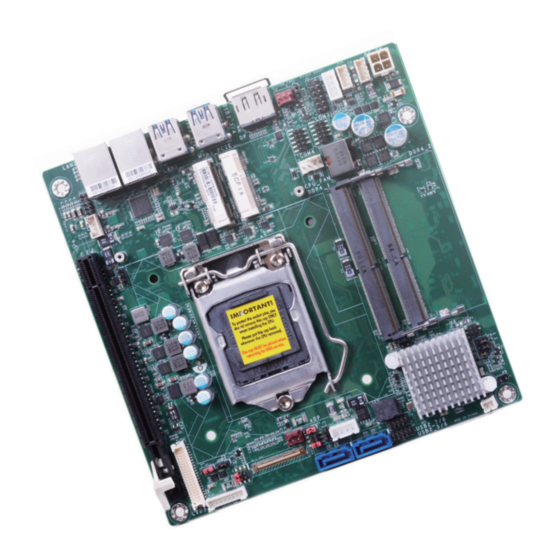
Page 6: Chapter 1 - Introduction
REAR I/O Ethernet 2 x GbE (RJ-45) Humidity Operating: 5 to 90% RH Storage: 5 to 90% RH 4 x USB 3.0 MECHANICAL Dimensions Mini-ITX Form Factor Display 1 x DP++ 170mm (6.7") x 170mm (6.7") Chapter 1 Introduction www.dfi.com... -
Page 7: Features
USB 2.0. It is a marked improvement in device transfer speeds between your computer and a wide range of simultaneously accessible external Plug and Play peripherals. Chapter 1 Introduction Chapter 1 Introduction www.dfi.com... -
Page 8: Chapter 2 - Hardware Installation
Power-off the PC and then PCIe x16 (PCIE1) LVDS LCD Audio Buzzer unplug the power cord prior to installing any devices. Failure to do so Speaker Panel will cause severe damage to the motherboard and components. Chapter 2 Hardware Installation www.dfi.com... -
Page 9: System Memory
Enable or disable ECC in the “Advanced” menu of the BIOS. Refer to Chapter 3 for more infor- mation. Retention Notch DDR4_2 Notch DDR4_1 DDR4 SO-DIMM Retention Clip Socket Top View Features • Two 260-pin SODIMM up to 32GB • Dual Channel DDR4 1866/2133MHz 4 5 ° Chapter 2 Hardware Installation www.dfi.com... -
Page 10: Cpu
Inspect that the clip sits in the notch. If not, please pull the clips outward, release and remove the Step 3 card, and mount it again. Chapter 2 Hardware Installation www.dfi.com... -
Page 11: Installing The Cpu
Load lever Golden triangular 7.1.Insert the CPU into mark the socket. The gold triangular mark on the CPU must align with the chamfer corner of the CPU socket shown in the photo. Retention tab Chapter 2 Hardware Installation www.dfi.com... - Page 12 The CPU will fit in only one orientation and can easily be seated without exerting any force. 7.3.The CPU’s notch will fit into the socket’s alignment key when it’s seated in the cor- rect orientation. Chapter 2 Hardware Installation www.dfi.com...
-
Page 13: Installing The Fan And Heat Sink
4 mount- ing holes around the socket. 3. Orient the heat sink so that the CPU fan’s CPU fan cable is nearest the connector CPU fan connector. Chapter 2 Hardware Installation www.dfi.com... -
Page 14: Jumper Settings
2. Put a jumper cap on JP5’s pin 2 and pin 3. Wait for a few seconds and set JP5 back to its default setting, i.e. jumper cap on pin 1 and pin 2. 3. Plug the power cord and power-on the system. Chapter 2 Hardware Installation www.dfi.com... -
Page 15: Lvds Panel Power Select
LCD panel’s specification. Selecting the incorrect voltage will seriously damage the PCIe x16 (default) 1 On, 2 On LCD panel. Two PCIe x8 1 Off, 2 On One PCIe x8 + Two PCIe x4 1 Off, 2 Off Chapter 2 Hardware Installation www.dfi.com... -
Page 16: Lcd/Inverter Power Select
JP6 is used to select the power level of backlight brightness control of the LVDS port: +3.3V or +5V. Important: Before powering-on the system, make sure that the power settings of JP6 match the power specification of backlight control. Selecting the incorrect voltage will se- riously damage the backlight. Chapter 2 Hardware Installation www.dfi.com... -
Page 17: Mini Pcie 1 Signal Select
(default) JP4 is used to select the Mini PCIe 1 (full-size) signal: mini PCIe or mSATA (default). JP3 is used to select the Mini PCIe 2 (half-size) signal: mini PCIe (default) or mSATA. Chapter 2 Hardware Installation www.dfi.com... -
Page 18: Edp Panel Power Select
JP2 is used to select the power level of the eDP inverter power connector. Important: Before powering-on the system, make sure that the power settings of JP10 match the panel’s specification. Selecting the incorrect voltage will seriously damage the LCD panel. Chapter 2 Hardware Installation www.dfi.com... -
Page 19: Edp Backlight Power Select
JP9 is used to select the power level of backlight brightness control of the eDP port: +3.3V or +5V. Important: Before powering-on the system, make sure that the power settings of JP9 match the power specification of backlight control. Selecting the incorrect voltage will se- riously damage the backlight. Chapter 2 Hardware Installation www.dfi.com... -
Page 20: Rear Panel I/O Ports
The DP port is a digital display interface used to connect a display device such as a computer monitor. It is used to transmit audio and video simultaneously. The interface, which is devel- oped by VESA, delivers higher performance features than any other digital interface. Chapter 2 Hardware Installation www.dfi.com... -
Page 21: Rj45 Lan Ports
You may need to install the proper drivers in your system operation to use the USB device. • Intel I219LM PCIe with iAMT11.0 Gigabit Ethernet Phy ® Refer to your operating system’s manual or documentation for more information. Chapter 2 Hardware Installation www.dfi.com... -
Page 22: I/O Connectors
Configure the Serial ATA drives in the Advanced menu (“SATA Configuration” submenu) of the BIOS. Refer to the chapter 3 for more information. Features 2 x Serial ATA 3.0 ports with data transfer rate up to 6Gb/s (SATA 0 and SATA 3) Chapter 2 Hardware Installation www.dfi.com... -
Page 23: Digital I/O
▼ Digital I/O Connector Pin assignment The Advanced menu (“SIO NUVOTON6106D” submenu) of the BIOS will display the current speed of the cooling fans. Refer to the chapter 3 for more information. Function DIO0 DIO1 DIO2 DIO3 Chapter 2 Hardware Installation www.dfi.com... -
Page 24: Chassis Intrusion Connector
HDD Power P W R - L E D LED Power H D - L E D Signal Signal Ground Ground R E S E T A T X - S W Signal Signal N.C. Chapter 2 Hardware Installation www.dfi.com... -
Page 25: Expansion Slots
The PCIe x16 slot can be switched between riser card and x16 signal, and the two Mini PCIe slots can be switched between PCIe signal and m-SATA signal. The settings are configured via jumpers as previously instructed in Chapter 2. Chapter 2 Hardware Installation www.dfi.com... -
Page 26: Standby Power Led
Screw tight the card onto the stand- off with a screw driver and a stand- off screw until the gap between the card and the stand-off closes up. The card should be lying parallel to the board when it’s correctly mount- Chapter 2 Hardware Installation www.dfi.com... -
Page 27: Lvds Panel
Panel Power 3 for more information. LCD/Inverter Power Pin Function Pin Function Pin Assignment +3.3V Note: DFI board's LVDS connector: Hirose DF13-40DP-1.25V(91)/40P/1.25mm; cable side Panel Backlight On/Off connector: Hirose DF13-40DS-1.25C. Control Panel Inverter Brightness 12V (default)/5V Voltage Control Panel Power... -
Page 28: Smbus Connector
The speaker connector is used to connect external speakers. multiple device bus that allows multiple chips to connect to the same bus and enable each one to act as a master by initiating data transfer. Chapter 2 Hardware Installation www.dfi.com... -
Page 29: Com (Serial) Ports
Make sure the colored stripe on the ribbon cable is aligned with pin 1 of the COM connector. BIOS Setting Configure the serial COM ports in the Advanced menu (“SIO NUVOTON6106D” submenu) of the BIOS. Refer to the chapter 3 for more information. Chapter 2 Hardware Installation www.dfi.com... -
Page 30: Power Atx Mode
Connect a DC power cord to this connector. Using a voltage more than the recommended range may fail to boot the system or cause damage to the system board. Chapter 2 Hardware Installation www.dfi.com... -
Page 31: Edp Connector
Inverter Power Note: DFI board's eDP connector: I-PEX 20455-040E-76 (40 Pin, 90D, 0.5mm). Inverter Power eDP Panel Power Inverter Power eDP Panel Power Inverter Power... -
Page 32: Battery
Safety Measures • There exists explosion hazard if the battery is incorrectly installed. • Replace only with the same or equivalent type recommended by the manufacturer. • Dispose of used batteries according to local ordinances. Chapter 2 Hardware Installation www.dfi.com... -
Page 33: Chapter 3 - Bios Setup
“Reset” button. You may also additional options are available for that field. To display the submenu, move the highlight to restart the system by pressing the <Ctrl> <Alt> and <Del> keys simultaneously. that field and press <Enter>. Chapter 3 BIOS Setup www.dfi.com... -
Page 34: Main
Security Boot Exit Setting incorrect field values may cause the system to malfunction. This is the help for the Project Name SD106 hour, minute, second field. BIOS Version B194.25A Valid range is from 0 to Supported Processor Intel 6th and 7th Generation CPU 23, 0 to 59, 0 to 59. -
Page 35: Acpi Configuration
BGRT Logo field will appear for configuration. Refer to the Boot menu for more battery. information. Wake up time When Wake On RTC is set to enabled, specify the wake up time of the day: <hour> (00~23), <minute> (00~59), <second> (00~59). Chapter 3 BIOS Setup www.dfi.com... -
Page 36: Cpu Configuration
Boot Type : Legacy Boot Type -> Hide Primary Display & Show Boot display Boot Type : UEFI Boot Type -> Show Primary Display & Hide Boot display Boot Type : Dual Boot Type -> Show Primary Display & Show Boot display Chapter 3 BIOS Setup www.dfi.com... -
Page 37: Audio Configuration
Please check the specifications of your LCD monitor. Select the type of LCD panel connected to the system’s LCD connector: VBIOS Default, 800x480, 800x600, 1024x768, 1366x768, Auto HDA will be enabled if present, disabled otherwise. 1280x1024 or 1920x1080. Chapter 3 BIOS Setup www.dfi.com... -
Page 38: Sata Configuration
RAID This option allows you to create RAID or Intel Matrix Storage configuration on Se- rial ATA devices. Port 0, 1, 2, 3 and Hot Plug These fields are used to enable or disable the serial ATA port and its hot plug. Chapter 3 BIOS Setup www.dfi.com... -
Page 39: Pci Express Configuration
Save and Exit PCIe Speed Select the speed of the PCI Express Root Port: Auto, Gen1, Gen2 or Gen3. Hot Plug This field is used to enable or disable the PCI Express Hot Plug. Chapter 3 BIOS Setup www.dfi.com... -
Page 40: Me Configuration
This field is used to enable or disable the flash ME region. This field is used to enable or disable Intel Active Management Technology. ® Un-Configure ME This field is used to enable or disable to un-configure ME with resetting MEBX password to default. Chapter 3 BIOS Setup www.dfi.com... -
Page 41: Mebx Configuration
Save and Exit Dynamic EFI DEBUG This field is used to turn on or off the function to output debug message from COM port. If set to on, relevant EFI debug configuration will show up. Chapter 3 BIOS Setup www.dfi.com... -
Page 42: Device Manager
Enter numeric value for EFI Debug Print Level and default is 0x8000004F. EFI debug serial port Enter serial port to output EFI debug message and default is 0x3F8. EFI debug baud rate Enter baud rate to output EFI debug message and default is 115200. Chapter 3 BIOS Setup www.dfi.com... -
Page 43: Sio Nuvoton6106D
1, the system or CPU fan should be turned on and operate at the designated speed. The range is from 0-127 Fan Speed Count 1 to Fan Speed Count 4 Set the fan speed. The range is from 1-100% (full speed). Chapter 3 BIOS Setup www.dfi.com... - Page 44 User configuration Enable or disable the watchdog function. A counter will appear if you select to enable WDT. Input any value between 1 to 255 seconds. Case Open Enable or disable the case open detection function. Chapter 3 BIOS Setup www.dfi.com...
-
Page 45: Console Redirection
Select data bits: 7 bits or 8 bits. Parity Select parity bits: none, even or odd. Stop Bits Select stop bits: 1 bit or 2 bits. Flow Control Select flow control type: none, RTS/CTS or XON/XOFF. Chapter 3 BIOS Setup www.dfi.com... - Page 46 This field is to enable or disable to use global setting. When enabled the global setting, setting of the COM port will be the same as those in Console Redirection section. When disabled the global setting, setting of the COM port can be configured independently in this section. Chapter 3 BIOS Setup www.dfi.com...
-
Page 47: Security
Please refer to Chapter 5 ˗ RAID for more information. Network Stack This field is used to enable or disable network stack. PXE Boot capability Disabled Suppoort Network Stack UEFI IPv4/IPv6 Legacy Legacy PXE OPROM only Chapter 3 BIOS Setup www.dfi.com... -
Page 48: Exit
Select YES and then press <Enter> to exit the system setup without saving your changes. Help ↑/↓ Select Item F5/F6 Change Values Setup Defaults Exit ←/→ Select Item Enter Select SubMenu Save and Exit Chapter 3 BIOS Setup www.dfi.com... -
Page 49: Updating The Bios
BIOS with the flash utility. For updating Insyde BIOS in UEFI mode, you may refer to the how-to video at https://www.dfi.com/tw/knowledge/video/31. ► Notice: BIOS SPI ROM 1. -
Page 50: Chapter 4 - Supported Software
If after inserting the DVD, “Autorun” did not automatically start (which is, the Mainboard Utility DVD screen did not appear), please go directly to the root directory of the DVD and double- click “Setup”. ► Auto-run Menu For Windows 10 Chapter 4 Supported Software www.dfi.com... - Page 51 Intel chipset can be recognized and configured properly in the system. To install the utility, click “Intel Chipset Software Installation Utility” on the main menu. 1. Setup is ready to install the utility. Click Next. 2. Read the license agreement then click Yes. Chapter 4 Supported Software www.dfi.com...
- Page 52 1 to 2 minutes (while WinSAT is running) before the Windows 7/Windows 8.1/Windows 10 desktop appears. The “blank screen” period is the time Windows is testing the graphics performance. 2. Read the license agreement then click Yes. Chapter 4 Supported Software www.dfi.com...
- Page 53 Restarting the system will allow the new software installation to take effect. 5. Click “Yes, I want to restart this computer now” then click Finish. Restarting the system will allow the new software installation to take effect. Chapter 4 Supported Software www.dfi.com...
- Page 54 1. Setup is ready to install the driver. Click Next. 5. After completing installa- tion, click Finish. 2. Click “I accept the terms in the license agreement” then click “Next”. 3. Select the program featuers you want installed then click Next. Chapter 4 Supported Software www.dfi.com...
- Page 55 3. Click “Restart Now“ to restart your computer when the installation is complete. To install the driver, click “Kernel Mode Driver Framework” on the main menu. 1. Click “Yes“ to install the update. 2. The update is installed now. Chapter 4 Supported Software www.dfi.com...
- Page 56 1. Setup is ready to install the driver. Click Next. 4. Please wait while the prod- uct is being installed. 2. Read the license agreement then click Next. 5. After completing installa- tion, click Finish. Chapter 4 Supported Software www.dfi.com...
- Page 57 1. Setup is ready to install the driver. 4. The wizard is ready to begin installation. Click “Install”. 2. Click “Next” to continue. 5. Please wait while the program features are being installed. Chapter 4 Supported Software www.dfi.com...
- Page 58 Chapter 4 6. After completing installa- The HW Utility icon will appear on the desktop. Double-click the icon to open the utility. tion, click “Finish”. Information HW Health Chapter 4 Supported Software www.dfi.com...
- Page 59 Chapter 4 HW Health Set Backlight WatchDog Chapter 4 Supported Software www.dfi.com...
- Page 60 1. Setup is ready to install the driver. Click Next. 4. Setup is currently installing the driver. After installation has com- pleted, click Next. 2. Read the license agreement then click Yes. 5. After completing installation, click Finish. Chapter 4 Supported Software www.dfi.com...
- Page 61 1. Setup is ready to install the driver. Click Next. 4. Setup is ready to install the driver. Click Next. 2. Read the license agreement care- fully. Click “I accept the terms in the cense Agreement” then click Next. Chapter 4 Supported Software www.dfi.com...
- Page 62 To install the driver, click “Microsoft Framework 4.5.2” on the main menu. 1. Setup is now extracting files. 6. Click Finish. 2. Read the license agreement care- fully. Click “I have read and accept the terms of the License Agree ment” then click Install. Chapter 4 Supported Software www.dfi.com...
- Page 63 SATA drives. It enables enhanced performance and power management for the storage subsystem. To install the driver, click “Intel Rapid Storage Technology” on the main menu. Please refer to Chapter 5 for more information. 4. Click Finish. Chapter 4 Supported Software www.dfi.com...
- Page 64 4. Enter the necessary information and then click Next. 2. The setup program is now ready to install the utility. Click Next. 5. Select a setup type and then click Next. Chapter 4 Supported Software www.dfi.com...
- Page 65 7. TPM requires installing the Micro- 10. Click “Yes“ to restart your system. soft Visual C++ package prior to installing the utility. Click Install. 8. The setup program is currently installing the Microsoft Visual C++ package. Chapter 4 Supported Software www.dfi.com...
- Page 66 To install the reader, click “Adobe Acrobat Reader 9.3” on the main menu. 1. Click Next to install or click Change Destination Folder to select another folder. 2. Click Install to begin installa- tion. 3. Click Finish to exit installation. Chapter 4 Supported Software www.dfi.com...
-
Page 67: Chapter 5 - Raid
Single Drive Failure Disk mirroring Block-level data striping with RAID 5 Single Drive Failure distributed parity 1 Disk Per Mirrored Combination of RAID 0 (data striping) RAID 10 Stripe (not same mirror) and RAID 1 (mirroring) Chapter 5 RAID www.dfi.com... - Page 68 5. Press <Enter>. 6. Use the up or down arrow keys to select the strip size and press <Enter>. 7. Enter the volume size and press <Enter>. 8. At the prompt, press <Y> to confirm volume creation. Chapter 5 RAID www.dfi.com...
- Page 69 RAID volume and/ or SATA drives. It enables enhanced performance and power management for the storage subsystem. 1. Download “SD106 IRST Driver” zip file at our website. 2. Setup is ready to install the utility. Click “Next”.
- Page 70 Chapter 5 7. Click “Yes, I want to restart this computer now” to complete the installation and then click “Finish”. Chapter 5 RAID www.dfi.com...
-
Page 71: Chapter 6 - Intel Amt Settings
MEBx Setup. Note : This option does not dis- able Manageability Fea- tures in FW. Help ↑/↓ Select Item F5/F6 Change Values Setup Defaults Exit ←/→ Select Item Enter Select SubMenu Save and Exit Chapter 6 Intel AMT Settings www.dfi.com... - Page 72 InsydeH2O Setup Utility Rev. 5.0 Advanced Rev. 5.0 MEBX Configuration MEBX Configuration Set- ting MEBX Configuration Help ↑/↓ Select Item F5/F6 Change Values Setup Defaults Exit ←/→ Select Item Enter Select SubMenu Save and Exit Chapter 6 Intel AMT Settings www.dfi.com...
- Page 73 • Both lower case and upper case characters Intel(R) ME New Password You will be asked to verify the new password. Enter the same new password in the prompt and then press Enter. Verify password Chapter 6 Intel AMT Settings www.dfi.com...
- Page 74 • Both lower case and upper case characters Intel(R) ME New Password You will be asked to verify the new password. Enter the same new password in the space pro- vided under Verify Password then press Enter. Verify password Chapter 6 Intel AMT Settings www.dfi.com...
- Page 75 > User Consent Password Policy <Anytime> > Network Setup Disabled Activate Network Access Enabled Unconfigure Network Access <Full Unprovision> > Remote Setup And Configuration > Power Control [↑↓] =Move Highlight <Enter> =Complete Entry [Esc] =Discard Changes Chapter 6 Intel AMT Settings www.dfi.com...
- Page 76 Select Enabled or Disabled then press Enter. Select Enabled or Disabled then press Enter. Storage Redirection Select Enabled or Disabled then press Enter. KVM Feature Selection Select Enabled or Disabled then press Enter. Disabled Enabled Chapter 6 Intel AMT Settings www.dfi.com...
- Page 77 You may choose to use a password only during setup and configuration or to use a password User Opt-in anytime the system is being accessed. Select NONE or KVM or ALL then press Enter. NONE Opt-in Configurable from Remote IT Select Enabled or Disabled then press Enter. Disabled Enabled Chapter 6 Intel AMT Settings www.dfi.com...
- Page 78 Enter the computer’s domain name and then press Enter. > Intel(R) ME Network Name Settings > TCP/IP Settings Computer Domain Name Shared/Dedicated FQDN Select Shared or Dedicated and then press Enter. Dedicated [↑↓] =Move Highlight [Enter] =Select Entry [Esc] =Exit Shared Chapter 6 Intel AMT Settings www.dfi.com...
- Page 79 > Wired LAN IPV4 Configuration <Enter> =Complete Entry [Esc] =Discard Changes Enter a value for the Time-to-live (TTL) field and then press Enter. Value in Seconds [↑↓] =Move Highlight [Enter] =Select Entry [Esc] =Exit Chapter 6 Intel AMT Settings www.dfi.com...
- Page 80 Default Gateway Address 0.0.0.0 Preferred DNS Address 0.0.0.0 Alternate DNS Address 0.0.0.0 Alternate DNS Address Insert a value from 0.0.0.0 to 255.255.255.255 in IPv4 format. Alternate DNS address 0.0.0.0 <Enter> =Complete Entry [Esc] =Discard Changes Chapter 6 Intel AMT Settings www.dfi.com...
- Page 81 Activates the current network settings > Power Control Full Unprovision and opens the ME network interface Continue: (Y/N) [↑↓] =Move Highlight [Enter] =Select Entry [Esc] =Exit [↑↓] =Move Highlight <Enter> =Complete Entry [Esc] =Discard Changes Chapter 6 Intel AMT Settings www.dfi.com...
- Page 82 > RCFG > TLS PKI Provisioning Server FQDN Enter the Fully Qualified Domain Name (FQDN) of the server and then press Enter. Enter FQDN of provisioning server [↑↓] =Move Highlight [Enter] =Select Entry [Esc] =Exit Chapter 6 Intel AMT Settings www.dfi.com...
- Page 83 [Enter] =Select Entry [Esc] =Exit Remote Configuration ** Select Enabled or Disabled then press Enter. Disabled Enabled PKI DNS Suffix Specify the DNS Suffix of the PKI server, and then press Enter. Enter PKI DNS Suffix Chapter 6 Intel AMT Settings www.dfi.com...
- Page 84 Desktop: ON in S0, ME Wake in S3, S4-5 [Ins] =Add New Hash [Delete] =Delete Hash [+] =Activate Hash [↑↓] =Move Highlight [Enter] =View Hash [Esc] =Exit Idle Timeout Enter a timeout value and press Enter. Timeout Value (1-65535) 65535 Chapter 6 Intel AMT Settings www.dfi.com...
- Page 85 Copyright(C) 2003-16 Intel Corporation. All Rights Reserved MAIN MENU > Intel(R) ME General Settings > Intel(R) AMT Configuration MEBx Exit Are you sure you want to exit?(Y/N): Exit [↑↓] =Move Highlight [Enter] =Select Entry [Esc] =Exit Chapter 6 Intel AMT Settings www.dfi.com...
Need help?
Do you have a question about the SD106 and is the answer not in the manual?
Questions and answers