Table of Contents
Advertisement
Quick Links
Advertisement
Table of Contents

Subscribe to Our Youtube Channel
Related Manuals for DFI SD330-H110


Summary of Contents for DFI SD330-H110
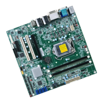
- Page 1 SD330-H110 MicroATX Industrial Motherboard User’s Manual A40620936...
-
Page 2: Copyright
Copyright FCC and DOC Statement on Class B This publication contains information that is protected by copyright. No part of it may be re- This equipment has been tested and found to comply with the limits for a Class B digital produced in any form or by any means or used to make any transformation/adaptation without device, pursuant to Part 15 of the FCC rules. -
Page 3: Table Of Contents
Table of Contents RJ45 LAN Ports ................... 22 USB Ports ....................22 Audio ......................23 I/O Connectors ................... 24 SATA (Serial ATA) Connectors ..............24 Copyright ......................2 Digital I/O Connector .................. 24 Cooling Fan Connectors................25 Trademarks ......................2 Power Connectors ..................25 LVDS LCD Panel Connector ................. -
Page 4: Warranty
Warranty Static Electricity Precautions 1. Warranty does not cover damages or failures that arised from misuse of the product, It is quite easy to inadvertently damage your PC, system board, components or devices even inability to use the product, unauthorized replacement or alteration of components and before installing them in your system unit. -
Page 5: About The Package
The package contains the following items. If any of these items are missing or damaged, please contact your dealer or sales representative for assistance. • One SD330-H110 motherboard • One COM port cable (Length: 300mm, 2 x COM ports) •... -
Page 6: Chapter 1 - Introduction
Chapter 1 - Introduction Specifications SYSTEM Processor 7th Generation Intel ® Core™ Processors, LGA 1151 Socket REAR I/O PS/2 1 x PS/2 (mini-DIN-6) Intel ® Core™ i7-7700 Processor, Quad Core, 8M Cache, 3.6GHz (4.2GHz), 65W Display 1 x VGA Intel ®... -
Page 7: Features
Features • Wake-On-LAN • Watchdog Timer This feature allows the network to remotely wake up a Soft Power Down (Soft-Off) PC. It is supported via the onboard LAN port or via a PCI LAN card that uses the PCI PME (Power Man- agement Event) signal. - Page 8 • Power Failure Recovery When power returns after an AC power failure, you may choose to either power-on the system manually or let the system power-on automatically. • USB The system board supports the new USB 3.0. It is capable of running at a maximum transmis- sion speed of up to 5 Gbit/s (625 MB/s) and is faster than USB 2.0 (480 Mbit/s, or 60 MB/s) and USB 1.1 (12Mb/s).
-
Page 9: Chapter 2 - Hardware Installation
COM 6 Fan 2 COM 2 RS232/422/485 Select (JP11) COM 2 RS232/422/485 Select (JP12) • Two 288-pin DIMM up to 32GB COM 2 RS232/422/485 Select (JP13) Vertical USB 2.0 (Type A) • Dual Channel DDR4 1866/2133MHz Chapter 2 Hardware Installation www.dfi.com... -
Page 10: Installing The Dimm Module
DIMMs. Ejector tab Ejector tab Not all slots need to be populated. DIMMs of the same memory configuration Dual Channel are on different channels. 5. Note how the module is keyed to the socket. Notch Chapter 2 Hardware Installation www.dfi.com... -
Page 11: Cpu
8. The ejector tabs at the ends of the socket will automatically snap into the locked position to hold the module in place. Note: The system board used in the following illustrations may not resemble the actual board. These illustrations are for reference only. Chapter 2 Hardware Installation www.dfi.com... -
Page 12: Installing The Cpu
4. Unlock the socket by push- ing the load lever down, moving it sideways until it Protective cap is released from the reten- tion tab; then lift the load lever up. Load lever Retention tab Chapter 2 Hardware Installation www.dfi.com... - Page 13 Alignment key The CPU’s notch will at the same time fit into the socket’s alignment key. Alignment key Important: The CPU will fit in only one orientation and can easily be inserted without exerting any force. Chapter 2 Hardware Installation www.dfi.com...
-
Page 14: Installing The Fan And Heat Sink
4 mounting holes around the socket. CPU fan connector 3. Orient the heat sink such that the CPU fan’s cable is nearest the CPU fan con- nector. Chapter 2 Hardware Installation www.dfi.com... -
Page 15: Jumper Settings
2. Set JP1 pins 2 and 3 to On. Wait for a few seconds and set JP1 back to its default setting, flicker). pins 1 and 2 On. 3. Now plug the power cord and power-on the system. Chapter 2 Hardware Installation www.dfi.com... -
Page 16: Com1/Com2 Rs232/422/485 Select
JP13 must be set in accordance to JP11. The pin functions of the COM ports will vary ac- cording to the jumpers’ setting. DCD- RXD+ DATA+ RXD- DATA- TXD+ N.C. DTR- TXD- N.C. DSR- N.C. N.C. RTS- N.C. N.C. CTS- N.C. N.C. N.C. N.C. Chapter 2 Hardware Installation www.dfi.com... -
Page 17: Com1/Com2 Rs232/Power Select
JP9 (for COM 1) and JP14 (for COM 2) are used to configure Serial COM ports to pure RS232 or RS232 with power. The pin functions of COM 1 and COM 2 will vary according to JP9’s and JP14’s setting respectively. DTR- DTR- DSR- DSR- RTS- RTS- CTS- CTS- Chapter 2 Hardware Installation www.dfi.com... -
Page 18: Panel Power Select
JP4 is used to select the power level of the LCD/inverter power connector. Important: Before powering-on the system, make sure that the power settings of JP2 match the LCD panel’s specification. Selecting the incorrect voltage will seriously damage the LCD panel. Chapter 2 Hardware Installation www.dfi.com... -
Page 19: Backlight Power Select
Selecting the incorrect voltage will seriously damage the backlight. JP number USB Port JP31 USB 1/2 (USB 3.0) JP32 USB 3/4 (USB 3.0) USB 5/6 (USB 2.0) JP33 USB 7/8/9/10 (USB 2.0) JP34 USB 5/6 (USB 3.0) JP36 Chapter 2 Hardware Installation www.dfi.com... -
Page 20: Rear Panel I/O Ports
Configure the wake-up function of PS/2 keyboard/mouse in the Advanced menu (“ACPI Con- figuration” submenu) of the BIOS. Refer to the chapter 3 for more information. Important: The +5V_standby power source of your power supply must support ≥720mA. Chapter 2 Hardware Installation www.dfi.com... -
Page 21: Com (Serial) Ports
Configure the serial COM ports in the Advanced menu (“SIO NUVOTON6106D” submenu) of Install the graphics driver. Refer to the chapter 4 for more information. the BIOS. Refer to the chapter 3 for more information. Chapter 2 Hardware Installation www.dfi.com... -
Page 22: Rj45 Lan Ports
BIOS. Refer to the chapter 3 for more information. Driver Installation You may need to install the proper drivers in your system operation to use the USB device. Refer to your operating system’s manual or documentation for more information. Chapter 2 Hardware Installation www.dfi.com... -
Page 23: Audio
Configure these Audio devices in the Advanced menu (“Audio Configuration” submenu) of the BIOS. Refer to the chapter 3 for more information. Driver Installation Install the audio driver. Refer to the chapter 4 for more information. Chapter 2 Hardware Installation www.dfi.com... -
Page 24: I/O Connectors
8 series chipset are intermittently detected. Before using SSD devices ® or mSATA SSD devices, please check whether the device and the cable which are DIO3 used on the system board conform to Intel's official regulations. DIO2 +5VDU DIO1 +5VDU DIO0 Chapter 2 Hardware Installation www.dfi.com... -
Page 25: Cooling Fan Connectors
Insufficient power supplied to the system may result in instability or the add-in boards and peripherals not functioning properly. Calculating the system’s approximate power usage is important to ensure that the power supply meets the system’s consumption requirements. Chapter 2 Hardware Installation www.dfi.com... -
Page 26: Lvds Lcd Panel Connector
Configure the LCD panel in the Advanced menu (“Video Configuration” sub- Panel Power Panel Power menu) of the BIOS. Refer to the chapter 3 for more information. Panel Power Panel Power Note: DFI board's LVDS connector: Hirose DF13-40DP-1.25V(91)/40P/1.25mm; cable side connector: Hirose DF13-40DS-1.25C. Chapter 2 Hardware Installation www.dfi.com... -
Page 27: Chassis Intrusion Connector
This switch is used to power on or off the system. Pin Pin Assignment Pin Pin Assignment HDD Power LED Power HD-LED Signal PWR-LED LED Power Ground Signal RST Signal Ground RESET ATX-SW N.C. Signal Chapter 2 Hardware Installation www.dfi.com... -
Page 28: Standby Power Led
Failure to do so will cause severe damage to the motherboard and components. of the system chassis then connect the audio cable to the S/PDIF connector. Make sure pin 1 of the audio cable is aligned with pin 1 of the S/PDIF connector. Chapter 2 Hardware Installation www.dfi.com... -
Page 29: Smbus Connector
The pin functions of the LAN LED con- to act as a master by initiating data transfer. nector are listed below. Pin Assignment Pin Assignment GBE_LED_1000- GBE_LED_100- GBE_LED_LINK_ACT- 3V3DU LINK_1000_2 LINK_100_2 LINK_ACTIVITY_2 3V3DU Chapter 2 Hardware Installation www.dfi.com... -
Page 30: Lpc Connector
Connecting the EXT-RS232/RS485 Card to the Motherboard With DFI’s proprietary technology, SD330-H110 supports two extension modules for additional four COM ports. The EXT-RS232/RS485 card is connected to SD330-H110 via the LPC connector. The illustrations below guide you how to connect the extension module to the motherboard. -
Page 31: Expansion Slots
PCI card only) into the PCI slot. PCI Express x4 Slot Install PCI Express cards such as network cards or other cards that comply to the PCI Express specifications into the PCI Express x4 slot. Chapter 2 Hardware Installation www.dfi.com... -
Page 32: Chapter 3 - Bios Setup
Chapter 3 Chapter 3 - BIOS Setup Legends Overview Keys Function The BIOS is a program that takes care of the basic level of communication between the CPU and peripherals. It contains codes for various advanced features found in this system board. Right and Left arrows Moves the highlight left or right to select a menu. -
Page 33: Insyde Bios Setup Utility (For Intel 6Th Generation Cpu)
The Main menu is the first screen that you will see when you enter the BIOS Setup Utility. For SD330-H110, we support both Intel 6th and 7th generation CPU. If your BIOS indicates that it supports 6th and 7th generation CPU on main menu, please refer page 46~59. For BIOS sup- porting 6th generation CPU only, please refer page 33~45. - Page 34 Chapter 3 CPU Configuration ACPI Configuration This section is used to configure the CPU. This section is used to configure the system ACPI parameters. InsydeH20 Setup Utility Rev. 5.0 InsydeH20 Setup Utility Rev. 5.0 Advanced Advanced Determines the action tak- Allows more than two fre- ACPI Confi...
- Page 35 Chapter 3 Video Configuration Boot display This section configures the video settings. Set the display device combination. InsydeH20 Setup Utility Rev. 5.0 InsydeH20 Setup Utility Rev. 5.0 Advanced Advanced Keep IGFX enabled based Video Confi guration Chose display device com- Video Confi...
- Page 36 Chapter 3 Audio Configuration LCD Panel Type This section is used to configure the audio settings. Select the LCD panel type. InsydeH20 Setup Utility Rev. 5.0 InsydeH20 Setup Utility Rev. 5.0 Advanced Advanced Backlight Type Setting Video Confi guration Control Detection of the HD Audio <Enabled>...
- Page 37 Chapter 3 SATA Configuration USB Configuration This section is designed to select the SATA controller and the type of hard disk drive which are This section is used to configure the parameters of the USB device. installed in your system unit. InsydeH20 Setup Utility Rev.
- Page 38 Chapter 3 PCI Express Configuration This section configures settings relevant to PCI Express root ports. InsydeH20 Setup Utility Rev. 5.0 InsydeH20 Setup Utility Rev. 5.0 Advanced Advanced PCI Express Root Port 5 Control the PCI Express PCI Express Root Port 5 ...
- Page 39 Chapter 3 ME Configuration SIO NUVOTON6106D This section configures settings relevant to flash ME region. This section configures the system super I/O chip parameters. InsydeH20 Setup Utility Rev. 5.0 InsydeH20 Setup Utility Rev. 5.0 Advanced Advanced Enable/Disable Smart Fan SYS Smart Fan Control <Enable>...
- Page 40 Chapter 3 InsydeH20 Setup Utility Rev. 5.0 InsydeH20 Setup Utility Rev. 5.0 Advanced Advanced Fan Speed Count 1 [30] Confi gure Serial port using Fan Speed Count 1 [30] Fan Speed Count 2 [40] options: [Disable] No Con- Fan Speed Count 2 [40] Fan Speed Count 3 [50]...
-
Page 41: Security
Chapter 3 Security InsydeH20 Setup Utility Rev. 5.0 Advanced Enable/Disable Smart Fan SYS Smart Fan Control <Disable> Fix Fan Speed Count [50] CPU Smart Fan Control <Disable> Fix Fan Speed Count [50] InsydeH20 Setup Utility Rev. 5.0 SYS Smart Fan 2 Control <Disable>... - Page 42 Chapter 3 Storage Password Setup Page InsydeH20 Setup Utility Rev. 5.0 Main Advanced Security Boot Exit Device Name: [ST3160318AS] InsydeH20 Setup Utility Rev. 5.0 Security Mode: No Accessed Main Advanced Security Boot Exit Set Storage Password Storage Password Setup Current TPM Device <TPM 1.2>...
-
Page 43: Boot
Chapter 3 Boot InsydeH20 Setup Utility Rev. 5.0 InsydeH20 Setup Utility Rev. 5.0 Main Advanced Security Boot Exit Boot Select Normal Boot Option Selects Power-on state for Boot Device Priority Priority or Advance Boot Numlock Numlock <On> Option Priority Boot Type <Dual Boot Type>... - Page 44 Chapter 3 Legacy Boot Type Order This section is used to set legacy boot order. Use + and - keys to arrange the sequence of storage devices that the system’s hardware checks for the operating system’s boot files. The first device in the order list InsydeH20 Setup Utility Rev.
-
Page 45: Exit
Chapter 3 Exit InsydeH20 Setup Utility Rev. 5.0 Main Advanced Security Boot Exit Exit system setup and save your changes. Exit Saving Changes Load Optimal Defaults Discard Changes Help ↑/↓ Select Item F5/F6 Change Values Setup Defaults Exit ←/→ Select Item Enter Select... -
Page 46: Insyde Bios Setup Utility (For Intel 6/7Th Generation Cpu)
SD330-H110, we support both Intel 6th and 7th generation CPU. If your BIOS indicates that it supports 6th and 7th generation CPU on main menu, please refer page 46~59. For BIOS sup- porting 6th generation CPU only, please refer page 33~45. - Page 47 Chapter 3 ACPI Configuration Note: Under Dual Boot Type or UEFI Boot Type mode, if Quiet Boot is set to enabled, This section is used to configure the system ACPI parameters. BGRT Logo field will appear for configuration. Refer to the Boot menu (page 58) for more information.
- Page 48 Chapter 3 CPU Configuration Video Configuration This section is used to configure the CPU. This section configures the video settings. InsydeH2O Setup Utility Rev. 5.0 InsydeH2O Setup Utility Rev. 5.0 Advanced Advanced Initial priority: Video Confi guration AUTO: PEG -> PCIe -> Allows more than two fre- CPU Confi...
- Page 49 Chapter 3 Audio Configuration InsydeH2O Setup Utility Rev. 5.0 Advanced This section is used to configure the audio settings. Choose display device Video Confi guration combination Primary Display <Auto> Internal Graphics Device <Auto> InsydeH2O Setup Utility Rev. 5.0 Boot display <VGA+DVI>...
- Page 50 Chapter 3 SATA Configuration USB Configuration This section is designed to select the SATA controller and the type of hard disk drive which are This section is used to configure the parameters of the USB device. installed in your system unit. InsydeH2O Setup Utility Rev.
- Page 51 Chapter 3 PCI Express Configuration InsydeH2O Setup Utility Rev. 5.0 Advanced This section configures settings relevant to PCI Express root ports. Intel I211 Setting Intel I211 <Enabled> InsydeH2O Setup Utility Rev. 5.0 Advanced PEG PCI Express Port set- PCIE 1 ting ...
- Page 52 Chapter 3 ME Configuration Debug Configuration This section configures settings relevant to flash ME region. This section configures debug setting. InsydeH2O Setup Utility Rev. 5.0 InsydeH2O Setup Utility Rev. 5.0 Advanced Advanced Enable it to output debug Dynamic EFI DEBUG <Off>...
- Page 53 Chapter 3 UEFI Device Manager SIO NUVOTON6106D The section configures UEFI device with option ROM, such as LAN card, etc. This section configures the system super I/O chip parameters. InsydeH2O Setup Utility Rev. 5.0 InsydeH2O Setup Utility Rev. 5.0 Advanced Advanced Enable/Disable Smart Fan Device Manager Setting...
- Page 54 Chapter 3 Note: InsydeH20 Setup Utility Rev. 5.0 SYS Smart Fan Control, CPU Smart Fan Control, and SYS Smart Fan 2 Control can be Advanced ↑ switched to <Disable>. When they are disabled, it will enable "Fix Fan Speed Count". Fan Speed Count 3 [50] Fan Speed Count 4...
- Page 55 Chapter 3 Console Redirection PC Health Status This section configures settings relevant to console redirection. This section displays the PC health status. InsydeH2O Setup Utility Rev. 5.0 InsydeH2O Setup Utility Rev. 5.0 Advanced Advanced Enable Console Redirec- Console Redirection Setup PC Health Status tion Function Console Serial Redirect...
- Page 56 Chapter 3 When Console Serial Redirect is set to enabled, the screen will appear like below: COMA to COMF InsydeH2O Setup Utility Rev. 5.0 InsydeH2O Setup Utility Rev. 5.0 Advanced Advanced PortEnable <Enabled> Enable Console Redirec- Console Redirection Setup UseGlobalSetting <Enabled>...
-
Page 57: Security
Chapter 3 When UseGlobalSetting is set to disabled, the screen will appear like shown below: Security InsydeH2O Setup Utility Rev. 5.0 InsydeH2O Setup Utility Rev. 5.0 Advanced Main Advanced Security Boot Exit PortEnable <Enabled> UseGlobalSetting <Disabled> Install or Change the Pass- Current TPM Device <Not Detected >... -
Page 58: Boot
Chapter 3 Boot PXE Boot to LAN Disable or enable PXE boot to LAN. InsydeH2O Setup Utility Rev. 5.0 Main Advanced Security Boot Exit USB Boot Selects Power-on state for Numlock Numlock <Off> Boot Type <Dual Boot Type> Enable or disable to change USB boot devices boot order. Network Stack <Disabled>... -
Page 59: Exit
Chapter 3 Exit InsydeH2O Setup Utility Rev. 5.0 Main Advanced Security Boot Exit Exit system setup and save your changes. Exit Saving Changes Load Optimal Defaults Discard Changes Save Setting to fi le Help ↑/↓ Select Item F5/F6 Change Values Setup Defaults Exit ←/→... -
Page 60: Updating The Bios
Chapter 3 Notice: BIOS SPI ROM Updating the BIOS 1. The Intel Management Engine has already been integrated into this system board. Due to To update the BIOS, you will need the new BIOS file and a flash utility. Please contact techni- ®... -
Page 61: Chapter 4 - Supported Software
Please download drivers, utilities and software applications required to enhance the perfor- tion tips then click “Install”. mance of the system board at https://www.dfi.com/DownloadCenter . Intel Chipset Software Installation Utility The Intel Chipset Software Installation Utility is used for updating Windows ®... - Page 62 Chapter 4 Intel Graphics Drivers 3. Go through the readme document for system re- quirements and installation To install the driver, download “SD330 Graphics Driver” zip file at our website. tips then click “Next”. 1. Setup is now ready to install the graphics driver.
- Page 63 Chapter 4 Audio Drivers Intel LAN Drivers To install the driver, download “SD330 Audio Driver” zip file at our website. To install the driver, download “SD330 LAN Driver” zip file at our website. 1. Setup is ready to install the 1.
- Page 64 Chapter 4 Kernel Mode Driver Framework (For Windows 7 only) 4. Click “Install” to begin the installation. To install the driver, download “SD330 KMDF” zip file at our website. 1. Click “Yes” to install the update. 2. The update is installed 5.
- Page 65 Chapter 4 Intel Management Engine Interface Drivers 3. Click “Next” to install to the default folder, or click “Change” to choose another To install the driver, download “SD330 MEI Driver” zip file at our website. destination folder. 1. Setup is ready to install the driver.
- Page 66 Chapter 4 HW Utility 4. The wizard is ready to begin installation. Click “Install”. HW Utility provides information about the board, Watchdog and DIO. To access the utility, download “SD330 HW Utility” zip file at our website. Note: If you are using Windows 7, you need to access the operating system as an administrator to be able to install the utility.
- Page 67 Click “Next”. resemble the actual screen. The SD330-H110 HW Utility features the following tabs: Information, HW Health, HW Health- set, Watchdog, DIO and backlight. Click on the tabs to access information about the board. Chapter 4 Supported Software...
- Page 68 Chapter 4 IO Driver 3. Click “Next”. To install the driver, download “SD330 SIO Driver” zip file at our website. 1. Setup is ready to install the driver. Click “Next”. 4. Setup is currently installing the driver. After installation has com- pleted, click “Next”.
- Page 69 Chapter 4 3. Go through the readme docu- 5. Setup is now installing the ment for system requirements and driver. installation tips then click “Next”. 4. Setup is ready to install the driver. 6. Click “Yes, I want to restart Click “Next”.
- Page 70 Chapter 4 Microsoft Framework 4.5.2 (For Windows 7) 3. Setup is now installing the driver. Note: Before installing Microsoft Framework 4.5.2, make sure you have updated your Windows 7 operating system to Service Pack 3. To install the driver, download “SD330 DotNetFx45” zip file at our website. 1.
- Page 71 Chapter 4 Infineon TPM 1.2 Driver and Tool (optional) 4. Enter the necessary information and then click “Next”. To install the driver, download “SD330 TPM1.2 Utility” zip file at our website. 1. The setup program is preparing to install the driver. 5.
- Page 72 Chapter 4 7. TPM requires installing the Micro- 10. Click “Yes” to restart your system. soft Visual C++ package prior to installing the utility. Click “Install”. 8. The setup program is currently installing the Microsoft Visual C++ package. 9. Click “Finish”. Chapter 4 Supported Software www.dfi...
- Page 73 Chapter 4 Infineon TPM 2.0 Driver and Tool (optional) 4. Click “Restart now” to restart your system. To install the driver, download “TPM2.0 Hotfix” zip file at our website. 1. Click “OK”. 2. Click “Yes”. 3. Setup is now installing the up- dates.
- Page 74 Chapter 4 Adobe Acrobat Reader 9.3 4. Click “Finish” to exit installation. To install the reader, download “SD330-H110 Driver Package” iso file at our website. 1. Click “Next” to install or click “Change Destination Folder” to select another folder. 2. Click “Install” to begin instal- lation.
-
Page 75: Appendix A - Troubleshooting Checklist
Appendix A Appendix A - Troubleshooting Checklist The picture seems to be constantly moving. Troubleshooting Checklist 1. The monitor has lost its vertical sync. Adjust the monitor’s vertical sync. 2. Move away any objects, such as another monitor or fan, that may be creating a magnetic This chapter of the manual is designed to help you with problems that you may encounter field around the display. - Page 76 Appendix A Hard Drive System Board 1. Make sure the add-in card is seated securely in the expansion slot. If the add-in card is Hard disk failure. loose, power off the system, re-install the card and power up the system. 1.
Need help?
Do you have a question about the SD330-H110 and is the answer not in the manual?
Questions and answers