
Related Manuals for Elba EEC 566 WH


Summary of Contents for Elba EEC 566 WH
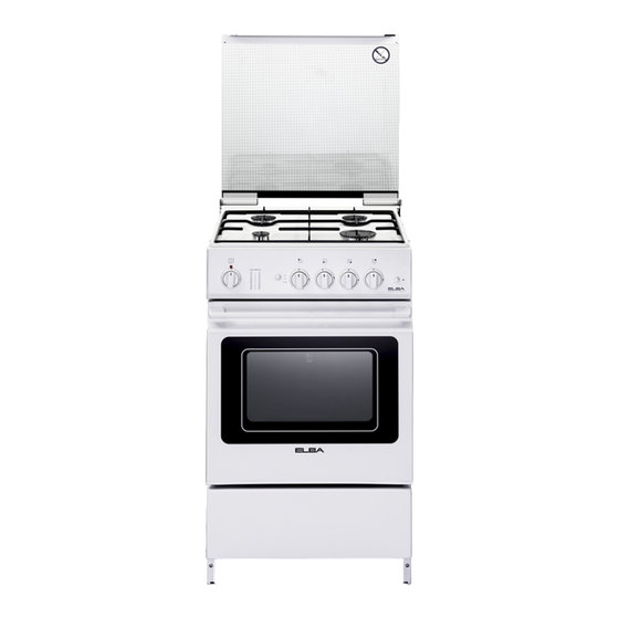
- Page 1 Instructions for the use - Installation advices DUAL FUEL COOKERS Models: EEC 566 WH ELBA QUALITY MADE IN ITALY Made in Italy...
- Page 2 Dear Customer, Thank you for having purchased and given your preference to our product. The safety precautions and recommendations reported below are for your own safety and that of others. They will also provide a means by which to make full use of the features offered by your appliance.
-
Page 3: Important Safety Precautions And Recommendations
IMPORTANT SAFETY PRECAUTIONS AND RECOMMENDATIONS IMPORTANT: This appliance is designed and manufactured solely for the cooking of domestic (household) food and is not suitable for any non domestic application and therefore should not be used in a commercial environment. The appliance guarantee will be void if the appliance is used within a non domestic environment i.e. - Page 4 • WARNING: Ensure that the appliance is switched off before replacing the oven lamp to avoid the possibility of electric shock. • Do not use a steam cleaner because the moisture can get into the appliance therefore making it unsafe. • Do not touch the appliance with wet or damp hands (or feet).
- Page 5 • Make sure that electrical cables connecting other appliances in the proximity of the cooker cannot come into contact with the hob or become entrapped in the oven door. • WARNING: Unattended cooking on a hob with fat or oil can be dangerous and may result in fire.
- Page 6 • Clean the oven regularly and do not allow fat or oils to build up in the oven base or tray. Remove spillages as soon as they occur. • Do not stand on the cooker or on the open oven door. • Always stand back from the appliance when opening the oven door to allow steam and hot air to escape before removing the food.
-
Page 7: Cooking Hob
COOKING HOB Fig. 1.1 GAS BURNERS Auxiliary burner (A) 1,00 kW Rapid burner (R) 3,00 kW Semi-rapid burner (SR) 1,75 kW Note: The appliance has a safety valve system fitted, the flow of gas will be stopped if and when the flame should accidentally go out. -
Page 8: Use Of The Hob Burners
USE OF THE HOB BURNERS Each burner is controlled by a gas tap (fig. 3.1) assuring the opening and the closing of the gas supply. Make the knob symbols match with the indicator on the control panel to obtain: • symbol : off •... -
Page 9: Lighting The Burners
LIGHTING THE BURNERS CHOICE OF THE BURNER ignite burner, following On the control panel, near every knob, instructions are to be followed: there is a diagram that indicates which Press in the corresponding knob and burner is controlled by that knob. turn counter-clockwise (fig. - Page 10 CORRECT USE OF RAPID BURNER The flat-bottomed pans are to be placed directly onto the pan-support. When using a WOK you need to place the supplied stand in the burner to avoid any faulty operation of the rapid burner (fig. 3.5a - 3.5b). IMPORTANT: The special grille for wok pans (fig.
-
Page 11: General Features
NATURAL CONVECTION ELECTRIC OVEN ELECTRICAL THERMOSTAT The glass of the oven door reaches high temperatures during operation. Turn on the oven or grill element by turning Keep children away. the switch that is also provided with a WARNING: thermostat to control the oven temperature. On the knob (fig. -
Page 12: Oven Cooking
USE OF THE GRILL WARNING: The door is hot, use the handle. Very important: The grill must always be During use the appliance becomes used with the oven door slightly open hot. Care should be taken to avoid and with shield “A” mounted (fig. 4.3). touching heating elements inside the Mount shield “A”... -
Page 13: Oven Light
OVEN LIGHT ROTISSERIE The oven is equipped with a light that The oven is equipped with a rotisserie for illuminates the oven to enable visually cooking on the spit using the grill. controlling the food that is cooking. This device is made up of: •... -
Page 14: Cleaning And Maintenance
CLEANING AND MAINTENANCE GLASS LID Models with glass lid For cleaning purposes, the lid can be easily removed upwards once taken to the upright position. Should the hinges slip off, replace them in their housing being careful that: • The right housing must receive the hinge marked “D”... -
Page 15: General Advice
GENERAL ADVICE ENAMELLED PARTS • Important! Before begin All the enamelled parts must be cleaned cleaning, you must ensure that with a sponge and soapy water or other the appliance is switched off and non-abrasive products. disconnected from the electrical Dry preferably with a microfibre or soft power supply. - Page 16 BURNERS CORRECT REPLACEMENT OF THE BURNERS They can be removed and washed with soapy water only. It is very important to check that the burner flame distributor “F” and the cap “C” has They will remain always perfect if cleaned been correctly positioned (see figs.
- Page 17 FITTING THE OVEN SHELF Security block • The oven shelf is provided with a security block to prevent accidental extraction. must inserted operating as per figure 5.4. • To pull it out operate in the inverse order. OVEN DOOR The internal glass of the oven door can be easily removed for cleaning by unscrewing the two lateral fixing screws (fig.
- Page 18 REPLACING OVEN LAMP REPLACING OVEN LAMP (MODELS WITH INCANDESCENT (MODELS WITH HALOGEN LAMP) LAMP) WARNING: Ensure the appliance is switched off and disconnected from the WARNING: Ensure the appliance is electrical power supply before replacing switched off and disconnected from the the lamp to avoid the possibility of electrical power supply before replacing electric shock.
-
Page 19: Removing The Oven Door
REMOVING THE OVEN DOOR The oven door can easily be removed as follows: • Open the door to the full extent (fig. 5.8a). • Open the lever “A” completely on the left and right hinges (fig. 5.8b). • Hold the door as shown in fig. 5.8. •... - Page 20 Advice for the installer IMPORTANT • Cooker installation must only be carried out by QUALIFIED TECHNICIANS and in compliance with local safety standards. Failure to comply with this condition will render the guarantee invalid. • The appliance must be installed in compliance with regulations in force in your country and in observation of the manufacturer’s instructions.
-
Page 21: Installation
INSTALLATION Product dimensions: 500x500x850 mm (WxDxH). The installation conditions, concerning protection against overheating of the surfaces adjacent to the cooker, must conform to figs. 6.1a/6.1b and 6.2. The appliance must be kept no less than 300 mm away from any side wall which exceeds the height of the hob surface (figs. -
Page 22: Ventilation Requirements
VENTILATION REQUIREMENTS The appliance must be installed in compliance with applicable local regulations concerning ventilation and the evacuation of exhaust gases. Intensive and prolonged use may require extra ventilation, e.g. opening a window, or more efficient ventilation increasing the mechanical suction power if this is fitted. CHOOSING SUITABLE SURROUNDINGS The room where the gas appliance is to be installed must have a natural flow of air so that the gas can burn (in compliance with applicable local regulations). -
Page 23: Gas Section
GAS SECTION GAS INSTALLATION REQUIREMENTS Important ! • The walls adjacent to the cooker must be of heat-resistant material. • Before installation, make sure that the local distribution conditions (gas type and pressure) and the adjustment of this appliance are compatible. The appliance adjustment conditions are given on the plate or the label. - Page 24 Fig. 7.1 THE PIPE DOES NOT CROSS THE REAR PANEL OF THE COOKER. IN CASE OF CROSSING THE BACK PANEL, ENSURE THE PIPE IS POSITIONED CLOSE TO THE BOTTOM PART OF THE APPLIANCE. POSSIBLE GAS CONNECTIONS GAS CONNECTION WITH A RUBBER HOSE Important! A rubber hose connection shall only be made if permitted by the applicable local regulations.
- Page 25 Make sure that the hose is tightly and securely fitted at both ends. Use a standard hose clamp (not supplied) to fasten the hose. Connecting the cooker to LPG If not already fitted, fit the LPG hose holder on the inlet pipe, making sure that you place the sealing washer between them (as shown in fig.
- Page 26 Gas connection with rubber hose holders Note: if not already fitted on the inlet pipe, the hose holders are supplied with the product in a separate kit. Inlet pipe Manifold male pipe fitting 1/2” G cylindrical (ISO 228-1) male Sealing washer (#) 1/2”...
- Page 27 • the flexiple pipe does not exceed 2000 mm in length (or refer to applicable local regulations) and does not come into contact with sharp edges, corners or moving parts. Use a single flexible pipe only; never connect the cooker with more than one flexible pipe. •...
-
Page 28: Lubrication Of The Gas Taps
GAS MAINTENANCE TABLE FOR THE CHOICE OF THE INJECTORS Natural Gas Town Gas G30 28-30 mbar Nominal Reduced G20 20 mbar G110 8 mbar G31 37 mbar BURNERS power power [kW] [kW] Ø injector Ø injector Ø injector [1/100 mm] [1/100 mm] [1/100 mm] Auxiliary (A) -
Page 29: Adjusting Of The Minimum Of The Top Burners
REPLACEMENT INJECTORS If the injectors are not supplied they can be obtained from the “Service Centre”. Select the injectors to be replaced according to the “Table for the choice of the injectors”. nozzle diameters, expressed hundredths of a millimetre, are marked on the body of each injector. -
Page 30: Electrical Section
ELECTRICAL SECTION N.B. For connection to the mains, do IMPORTANT: The cooker must be not use adapters, reducers or branching installed accordance with devices as they can cause overheating manufacturer’s instructions. and burning. Incorrect installation, which If the installation requires alterations to the manufacturer accepts domestic electrical system or if the socket... - Page 31 ELECTRICAL FEEDER CABLE CONNECTION WARNING: If the power supply cable is damaged, it must be replaced only by an authorised service agent in order to avoid a hazard. To connect the supply cable: • Remove the screws securing the cover “A” on the rear of the cooker (fig. 8.1). •...
- Page 32 The manufacturer reserves the right to make all modifications to its products deemed necessary for manufacturer commercial reasons at any moment and without prior notice, without jeopardising the essential functional and safety characteristics of the appliances. www.elba-cookers.it Made in Italy Cod. 1105407 - ß1...
Need help?
Do you have a question about the EEC 566 WH and is the answer not in the manual?
Questions and answers