Table of Contents
Advertisement
Quick Links
Advertisement
Table of Contents

Related Manuals for AXIOMTEK eBOX626-853-FL Series


Summary of Contents for AXIOMTEK eBOX626-853-FL Series
- Page 1 Series Embedded System User’s Manual...
-
Page 2: Disclaimers
Axiomtek does not make any commitment to update the information in this manual. Axiomtek reserves the right to change or revise this document and/or product at any time without notice. No part of this document may be reproduced, stored in a retrieval system, or transmitted, in any form or by any means, electronic, mechanical, photocopying, recording, or otherwise, without the prior written permission of Axiomtek Co., Ltd. -
Page 3: Safety Precautions
Safety Precautions Before getting started, please read the following important safety precautions. The eBOX626-853-FL does not come equipped with an operating system. An operating system must be loaded first before installing any software into the computer. Be sure to ground yourself to prevent static charge when installing the internal components. -
Page 4: General Cleaning Tips
General Cleaning Tips You may need the following precautions before you begin to clean the computer. When you clean any single part or component for the computer, please read and understand the details below fully. When you need to clean the device, please rub it with a piece of dry cloth. Be cautious of the tiny removable components when you use a vacuum cleaner to absorb the dirt on the floor. -
Page 5: Scrap Computer Recycling
If the computer equipment’s needs the maintenance or are beyond repair, we strongly recommended that you should inform your Axiomtek distributor as soon as possible for the suitable solution. For the computers that are no longer useful or no longer working well, please contact your Axiomtek distributor for recycling and we will make the proper arrangement. -
Page 6: Table Of Contents
Table of Contents Disclaimers ......................ii Safety Precautions ....................iii Classification ......................iii General Cleaning Tips ..................iv Scrap Computer Recycling ..................v SECTION 1 INTRODUCTION................. 1 General Description ................1 System Specifications ............... 2 1.2.1 CPU ........................2 1.2.2 I/O System ...................... - Page 7 SECTION 4 BIOS SETUP UTILITY .............. 31 Starting ..................... 31 Navigation Keys ................31 Main Menu ..................32 Advanced Menu ................33 Chipset Menu ................... 46 Security Menu .................. 49 Boot Menu ..................50 Save & Exit Menu ................51 APPENDIX A WATCHDOG TIMER .............
- Page 8 This page is intentionally left blank. viii...
-
Page 9: Section 1 Introduction
Series User’s Manual SECTION 1 INTRODUCTION This section contains general information and detailed specifications of the eBOX626-853-FL. The Section 1 includes the following sections: ◼ General Description ◼ System Specification ◼ Dimensions ◼ I/O Outlets ◼ Packing List ◼... -
Page 10: System Specifications
Series User’s Manual System Specifications 1.2.1 CPU ⚫ Intel® Celeron N3150 Quad Core SoC, 1.60GHz-2.08GHz Burst . ◼ ⚫ Integrated Graphics Intel Gen8 graphics: up to 12 EUs inside. ® ◼ Intel Graphics DX 11, OGL3.2. ® ◼ ⚫... -
Page 11: System Specification
1.2kg (2.65lb) without package/ 1.8kg(4.19lb) with package ⚫ Dimensions 200mm (7.87”) (W) x 120mm (4.72”) (D) x 46mm(1.81") (H) ◼ 1.2.4 Driver CD Content Please download the following eBOX640-521-FL drivers from the Axiomtek official website. ◼ Audio ◼ Chipset ◼... -
Page 12: Dimensions
Series User’s Manual Dimensions The following diagrams show you dimensions and outlines of the eBOX626-853-FL. 1.3.1 System Dimension Introduction... -
Page 13: Wall Mount Bracket Dimension
Series User’s Manual 1.3.2 Wall mount Bracket Dimension Introduction... -
Page 14: I/O Outlets
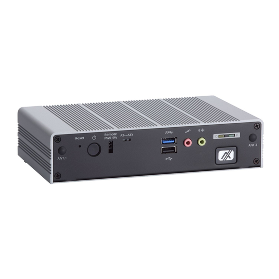
Series User’s Manual I/O Outlets The following figures show you I/O outlets on front view of the eBOX626-853-FL. ⚫ Front View ⚫ Front View drawing Introduction... - Page 15 Series User’s Manual ⚫ Rear View ⚫ Rear View drawing Introduction...
-
Page 16: Packing List
Pre-installed Foot pad x 4 ⚫ Terminal block connector x1 ⚫ ⚫ Remote power switch cable x 1 If you cannot find this package or any items are missing, please contact Axiomtek distributors immediately. Model List Fanless embedded system with Intel® Celeron® eBOX626-853-FL-N3150-DC N3150 2.08GHz quad core single chip design, 4 COM,... -
Page 17: Section 2 Hardware Installation
Series User’s Manual SECTION 2 HARDWARE INSTALLATION The eBOX626-853-FL is convenient for your various hardware configurations, such as Memory Module, HDD (Hard Disk Drive), SSD (Solid State Drive) and mSATA. The section 2 will show you how to install the hardware. - Page 18 Series User’s Manual Step 5 Locate the memory module, insert the gold colored of memory to contact into the socket. Step 6 Push the module down, until it is firmly seated by locking two latches on the sides. Step 7 Fasten all screws of bottom cover to finish installation.
-
Page 19: Installing The 2.5" Sata Hdd/Ssd
Series User’s Manual Installing the 2.5” SATA HDD/SSD Step 1 Turn off the system, and unplug the power cord. Step 2 Turn the system upside down to locate screws at the bottom, loosen screws. Step 3 Remove the bottom cover and then prepare your 2.5” HDD/SSD to assemble with your bottom cover. - Page 20 Series User’s Manual Step 5 Assembly the HDD on bottom cover and notice the connector position. Step 6 Fasten total four screws. Step 7 Connect SATA PWR and SATA Signal cables. Hardware Installation...
- Page 21 Series User’s Manual Step 8 Put the bottom cover back then fasten screws to finish the installation . Hardware Installation...
-
Page 22: Installing The Express Mini Card
Series User’s Manual Installing the Express Mini Card Step 1 Turn off the system, and unplug the power cord. Step 2 Turn the system upside down to locate screws at the bottom, loosen screws. Step 3 Find the location of Mini card slot. - Page 23 Series User’s Manual Step 5 Assembly the bottom cover back and fasten all screws to finish installation. Hardware Installation...
-
Page 24: Installing The Optional 8-Ch Dio Kit
Series User’s Manual Installing the optional 8-CH DIO kit Step 1 Turn off the system, and unplug the power cord. Step 2 Turn the system upside down to locate screws at the bottom, loosen screws. Step 3 Plug out the SCN8 connector of COM4 then loosen two hexagon pillars to remove COM4 cable. - Page 25 Series User’s Manual Step 5 Please notice the high spot of connector (10 pin) then connect it into SCN10. The high spot should be faced the mini card side. Step 6 Fasten two hexagon pillars with 8-CH DIO connector then complete installation.
- Page 26 Series User’s Manual This page is intentionally left blank. Hardware Installation...
-
Page 27: Section 3 Jumper Setting & Connector
Series User’s Manual SECTION 3 JUMPER SETTING & CONNECTOR Proper jumper settings configure the eBOX626-853-FL to meet your application purpose. We are herewith listing a summary table of all jumpers and default settings for onboard devices, respectively. SBC layout... - Page 28 Series User’s Manual NOTE: We strongly recommended that you should not modify any unmentioned jumper setting without Axiomtek FAE’s instruction. Any modification without instruction might cause system to become damage. Jumper Setting & Connector...
-
Page 29: Jumper Setting Summary
Series User’s Manual Jumper Setting Summary Proper jumper settings configure the eBOX626-853-FL to meet your application purpose. We are herewith listing a summary table of all jumpers and default settings for onboard devices, respectively. Jumper Description Jumper Setting Restore BIOS Optimal Defaults... -
Page 30: Connectors
Connectors connect the board with other parts of the system. Loose or improper connection might cause problems. Make sure all connectors are properly and firmly connected. Here is a summary table shows you all connectors and button on the eBOX626-853-FL Series. External Connectors... -
Page 31: Dc Phoenix Power In Connector
Series User’s Manual 3.3.1 DC Phoenix Power In Connector The system supports a wide range Phoenix DC-in connector (SCN2) for system power 9~36 VDC input. Signal 3.3.2 COM1~COM4 Serial Port Connector The system has four serial ports. COM1 is RS-232/422/485 port & COM2 to COM4 are RS-232 ports. -
Page 32: Vga Connector
Series User’s Manual 3.3.3 VGA Connector The VGA connector is a slim type 15-pin D-Sub connector which is common for the CRT VGA display. The VGA interface configuration can be configured via the software utility. Maximum resolution is up to 1920x1200@60Hz. -
Page 33: Lan Connector (Lan1, Lan2)
Series User’s Manual 3.3.5 LAN Connector (LAN1, LAN2) The RJ-45 connector is for Ethernet. To connect the board to a 1000/100/10 Base-T hub, just plug one end of the cable into connector and connect the other end (phone jack) to a 1000/100/10-Base-T hub. -
Page 34: At/Atx Switch
Series User’s Manual 3.3.9 AT/ATX Switch If you set AT/ATX switch to AT mode, the system will be automatically power on without pressing soft power button during power input; we can use this switch to achieve auto power on demand. -
Page 35: Audio Connector
Series User’s Manual 3.3.12 Audio Connector These two audio jacks ideal are for Audio Mic-In and Audio Line-out. Signal Microphone In Line Out 3.3.13 Option 8-CH DI/DO Connector eBOX626-853-FL supports one optional I/O output connector, and default set to COM4/RS-232 mode. -
Page 36: Sata Power Connector
Series User’s Manual 3.3.15 SATA Power Connector Use SCN14 for interfacing to SATA 2.5" HDD/SSD power supply. Signal +12V level +5V level 3.3.16 SIM Card Slot (SCN15) This board supports SCN15 socket on the bottom side for inserting SIM Card. In order to work properly, the SIM Card must be used together with 3G/LTE module which SCN16 is inserted. -
Page 37: Full-Size Pci Express Mini Card Slot (Scn13 & Scn16)
Series User’s Manual 3.3.17 Full-Size PCI Express Mini Card Slot (SCN13 & SCN16) eBOX626-853-FL supports dual full-size PCI-Express Mini Card slots. SCN16 is applying to either PCI-Express or USB 2.0 signal, and complies with PCI-Express Mini Card Spec. V1.2. - Page 38 Series User’s Manual SCN13: Signal Signal WAKE# +3.3V_SBY No use No use +1.5V CLKREQ# No use No use REFCLK-_3 No use REFCLK+_3 No use No use No use No use W_DISABLE# PERST# PE_RXN_3 +3.3V_SBY SATA_RXP PE_RXP_3 SATA_RXN +1.5V SMB_CLK...
-
Page 39: Section 4 Bios Setup Utility
Series User’s Manual SECTION 4 BIOS SETUP UTILITY This section provides users with detailed description how to set up basic system configuration through the BIOS setup utility. Starting To enter the setup screens, follow the steps below: Turn on the computer and press the <Del> key immediately. -
Page 40: Main Menu
Series User’s Manual Main Menu When you first enter the setup utility, you will enter the Main setup screen. You can always return to the Main setup screen by selecting the Main tab. System Time/Date can be set up as described below. -
Page 41: Advanced Menu
Series User’s Manual Advanced Menu The Advanced menu also allows users to set configuration of the CPU and other system devices. You can select any of the items in the left frame of the screen to go to the sub menus: ►... - Page 42 Series User’s Manual ⚫ ACPI Settings Enable Hibernation Enables or disables system ability to Hibernate. This option may be not effective with some ACPI Sleep State When the sleep button is pressed, the system will be in the ACPI sleep state. The default is S3 (Suspend to RAM).
- Page 43 Series User’s Manual ⚫ NCT6106D Super IO Configuration You can use this screen to select options for the Super IO Configuration, and change the value of the selected option. A description of the selected item appears on the right side of the screen.
- Page 44 Series User’s Manual ⚫ Serial Port 1 (COM1) Configuration Serial Port Enable or disable serial port 1. The optimal setting for base I/O address is 3F8h and for interrupt request address is IRQ4. COM Port Type Use this option to set RS-232/RS-422/RS-485 mode.
- Page 45 Series User’s Manual ⚫ Serial Port 2 (COM2) Configuration Serial Port Enable or disable serial port 2. The optimal setting for base I/O address is 2F8h and for interrupt request address is IRQ3. COM Port Type RS-232 mode. BIOS Setup Utility...
- Page 46 Series User’s Manual ⚫ Serial Port 3 (COM3) Configuration Serial Port Enable or disable serial port 3. The optimal setting for base I/O address is 3E8h and for interrupt request address is IRQ6. COM Port Type RS-232 mode. BIOS Setup Utility...
- Page 47 Series User’s Manual ⚫ Serial Port 4 (COM4) Configuration Serial Port Enable or disable serial port 3. The optimal setting for base I/O address is 2E8h and for interrupt request address is IRQ5. COM Port Type RS-232 mode. BIOS Setup Utility...
- Page 48 Series User’s Manual ⚫ NCT6106D HW Monitor This screen monitors hardware health status. This screen displays the temperature of system and CPU, and system voltages (VCORE, +3.3V, +12V and +5V). BIOS Setup Utility...
- Page 49 Series User’s Manual ⚫ DIO Configuration Users can adjust the option 8-CH DIO default setting via this page. eBOX626-853-FL doesn’t support 8-CH DIO option for standard version, users can order this kit then change the option port to support 8-CH TTL DIO.
- Page 50 Series User’s Manual ⚫ CPU Configuration This screen shows the CPU Configuration. Socket 0 CPU Information This item is for socket specific CPU information . Intel Virtualization Technology Allow a hardware platform to run multiple operating systems separately and simultaneously, enabling one system to virtually function as several systems.
- Page 51 Series User’s Manual ⚫ SATA Configuration In the SATA Configuration menu, you can see the currently installed hardware in the SATA ports. During system boot up, the BIOS automatically detects the presence of SATA devices. Serial-ATA Controller (SATA) Enable or disable the SATA Controller feature. The default is enabled.
- Page 52 Series User’s Manual ⚫ USB Configuration USB Devices Display all detected USB devices. Legacy USB Support Use this item to enable or disable support for USB device on legacy operating system. The default setting is Enabled. Auto option disables legacy support if no USB devices are connected.
- Page 53 Series User’s Manual ⚫ Utility Configuration Generally when you download a BIOS for eBOX626-853-FL, you will have included a matching AMI Flasher version. BIOS Flash Utility You can execute the BIOS flasher. BIOS Setup Utility...
-
Page 54: Chipset Menu
Series User’s Manual Chipset Menu The Chipset menu allows users to change the advanced chipset settings. You can select any of the items in the left frame of the screen to go to the sub menus: ► North Bridge ►... - Page 55 Series User’s Manual ⚫ North Bridge BIOS Setup Utility...
- Page 56 Series User’s Manual ⚫ South Bridge This screen allows users to configure parameters of South Bridge chipset. USB Configuration Enabled or Disabled the setting for XHCI Mode. Enabled or Disabled the setting for USB OTG Support. BIOS Setup Utility...
-
Page 57: Security Menu
Series User’s Manual Security Menu The Security menu allows users to change the security settings for the system. Administrator Password This item indicates whether an administrator password has been set (installed or uninstalled). User Password This item indicates whether an user password has been set (installed or uninstalled). -
Page 58: Boot Menu
Series User’s Manual Boot Menu The Boot menu allows users to change boot options of the system. Setup Prompt Timeout Number of seconds to wait for setup activation key. 65535(0xFFFF) means indefinite waiting. Bootup NumLock State Use this item to select the power-on state for the keyboard NumLock. -
Page 59: Save & Exit Menu
Series User’s Manual Save & Exit Menu The Save & Exit menu allows users to load your system configuration with optimal or fail-safe default values. Save Changes and Exit When you have completed the system configuration changes, select this option to leave Setup and return to Main Menu. - Page 60 Series User’s Manual Save Changes When you have completed the system configuration changes, select this option to save changes. Select Save Changes from the Save & Exit menu and press <Enter>. Select Yes to save changes. Discard Changes Select this option to quit Setup without making any permanent changes to the system configuration.
-
Page 61: Appendix Awatchdog Timer
Series User’s Manual APPENDIX A WATCHDOG TIMER About Watchdog Timer After the system stops working for a while, it can be auto-reset by the watchdog timer. The integrated watchdog timer can be set up in the system reset mode by program. - Page 62 Series User’s Manual Enable configuration: O 2E 87 ; Un-lock super I/O O 2E 87 Select logic device: O 2E 07 O 2F 08 WDT device disable: O 2E 30 O 2F 00 Watchdog Timer...
Need help?
Do you have a question about the eBOX626-853-FL Series and is the answer not in the manual?
Questions and answers