
Related Manuals for Mitsubishi Electric FR-D720-070


Summary of Contents for Mitsubishi Electric FR-D720-070
- Page 1 (217) 352-9330 | Click HERE Find the Mitsubishi FR-D720-070-NA at our website:...
- Page 2 INVERTER FR-D700 INSTRUCTION MANUAL FR-D720-008 to 318 - NA FR-D740-012 to 160 - NA FR-D720S-008 to 100 - NA OUTLINE WIRING PRECAUTIONS FOR USE OF THE INVERTER PARAMETERS TROUBLESHOOTING HEAD OFFICE: TOKYO BUILDING 2-7-3, MARUNOUCHI, CHIYODA-KU, TOKYO 100-8310, JAPAN PRECAUTIONS FOR MAINTENANCE AND INSPECTION SPECIFICATIONS IB(NA)-0600368ENG-A (0809)MEE Printed in Japan...
- Page 3 Thank you for choosing this Mitsubishi Inverter. This Instruction Manual provides instructions for advanced use of the FR-D700 series inverters. Incorrect handling might cause an unexpected fault. Before using the inverter, always read this instruction manual and the Installation Guideline [IB-0600367ENG] packed with the product carefully to use the equipment to its optimum performance.
- Page 4 3.Injury Prevention (3) Trial run CAUTION CAUTION Apply only the voltage specified in the instruction manual Before starting operation, confirm and adjust the to each terminal. Otherwise, burst, damage, etc. may parameters. A failure to do so may cause some machines occur.
- Page 5 (5) Emergency stop CAUTION Provide a safety backup such as an emergency brake which will prevent the machine and equipment from hazardous conditions if the inverter fails. When the breaker on the inverter input side trips, check for the wiring fault (short circuit), damage to internal parts of the inverter, etc.
-
Page 6: Table Of Contents
CONTENTS OUTLINE Product checking and parts identification......... 2 Inverter and peripheral devices............3 1.2.1 Peripheral devices .......................... 4 Removal and reinstallation of the cover ..........5 1.3.1 Front cover............................5 1.3.2 Wiring cover............................ 7 Installation of the inverter and enclosure design ......8 1.4.1 Inverter installation environment..................... - Page 7 3.1.1 Leakage currents and countermeasures ..................38 3.1.2 EMC measures..........................40 3.1.3 Power supply harmonics ......................42 Installation of power factor improving reactor ....... 43 Power-off and magnetic contactor (MC) .......... 44 Inverter-driven 400V class motor ............ 45 Precautions for use of the inverter ..........46 Failsafe of the system which uses the inverter ......
- Page 8 4.7.1 Setting of the acceleration and deceleration time (Pr. 7, Pr. 8, Pr. 20, Pr. 44, Pr. 45) ..................... 96 4.7.2 Starting frequency and start-time hold function (Pr. 13, Pr. 571)..........98 4.7.3 Acceleration/deceleration pattern (Pr. 29) ................... 99 Selection and protection of a motor..........100 4.8.1 Motor overheat protection (Electronic thermal O/L relay, PTC thermistor protection) (Pr.
- Page 9 4.14.1 Optimum excitation control (Pr. 60) ................... 147 4.15 Motor noise, EMI measures, mechanical resonance....148 4.15.1 PWM carrier frequency and Soft-PWM control (Pr. 72, Pr. 240, Pr. 260) ......... 148 4.15.2 Speed smoothing control (Pr. 653).................... 149 4.16 Frequency setting by analog input (terminal 2, 4) ....... 150 4.16.1 Analog input selection (Pr.
- Page 10 4.22 Setting the parameter unit and operation panel......237 4.22.1 RUN key rotation direction selection (Pr. 40)................237 4.22.2 PU display language selection(Pr.145)..................237 4.22.3 Operation panel frequency setting/key lock operation selection (Pr. 161)......... 238 4.22.4 Magnitude of frequency change setting (Pr. 295)..............240 4.22.5 Buzzer control (Pr.
- Page 11 6.1.6 Cleaning ............................. 266 6.1.7 Replacement of parts ......................... 267 Measurement of main circuit voltages, currents and powers ..271 6.2.1 Measurement of powers ......................273 6.2.2 Measurement of voltages and use of PT ..................273 6.2.3 Measurement of currents......................274 6.2.4 Use of CT and transducer ......................
- Page 12 MEMO Artisan Technology Group - Quality Instrumentation ... Guaranteed | (888) 88-SOURCE | www.artisantg.com...
- Page 13 OUTLINE This chapter explains the "OUTLINE" for use of this product. Always read the instructions before using the equipment Product checking and parts identification ......... 2 Inverter and peripheral devices........... 3 Removal and reinstallation of the cover ........5 Installation of the inverter and enclosure design ...... 8 <Abbreviations>...
-
Page 14: Product Checking And Parts Identification
• Accessory · Fan cover fixing screws (M3 × 35mm) These screws are necessary for compliance with the European Directive (Refer to Installation Guideline) Type Number FR-D720-070 to 165 FR-D740-036 to 080 FR-D720S-070, 100 FR-D720-120, 160 FR-D740-120, 160 Artisan Technology Group - Quality Instrumentation ... Guaranteed | (888) 88-SOURCE | www.artisantg.com... -
Page 15: Inverter And Peripheral Devices
Inverter and peripheral devices Inverter and peripheral devices Three-phase AC power supply Parameter unit (FR-PU07) Use within the permissible power supply By connecting the connection cable specifications of the inverter. To ensure (FR-CB2) to the PU connector, safety, use a moulded case circuit breaker, operation can be performed from earth leakage circuit breaker or magnetic FR-PU07. -
Page 16: Peripheral Devices
S-N10 FR-D720-025 0.4 (1/2) 30AF 5A 30AF 5A S-N10 S-N10 FR-D720-042 0.75 (1) 30AF 10A 30AF 5A S-N10 S-N10 FR-D720-070 1.5 (2) 30AF 15A 30AF 10A S-N10 S-N10 FR-D720-100 2.2 (3) 30AF 20A 30AF 15A S-N10 S-N10 FR-D720-165 3.7 (5) -
Page 17: Removal And Reinstallation Of The Cover
Removal and reinstallation of the cover Removal and reinstallation of the cover 1.3.1 Front cover FR-D720-165 or less FR-D740-080 or less FR-D720S-008 to 100 Removal (Example of FR-D740-036) 1) Loosen the installation screws of the front cover. (The screws cannot be removed.) 2) Remove the front cover by pulling it like the direction of arrow. - Page 18 Removal and reinstallation of the cover FR-D720-238, 318 and FR-D740-120, 160 Removal (Example of FR-D740-160) 1) Loosen the installation screws of the front cover. (The screws cannot be removed.) 2) Remove the front cover by pulling it like the direction of arrow with holding the installation hook on the front cover. Installation hook Installation screw...
-
Page 19: Wiring Cover
Removal and reinstallation of the cover 1.3.2 Wiring cover Removal and reinstallation FR-D720-165 or less and FR-D740-080 or less and FR-D720S-008 to 100 Hold the side of the wiring cover, and pull it downward for Also pull the wiring cover downward with holding a removal. -
Page 20: Installation Of The Inverter And Enclosure Design
Installation of the inverter and enclosure design Installation of the inverter and enclosure design When an inverter panel is to be designed and manufactured, heat generated by contained equipment, etc., the environment of an operating place, and others must be fully considered to determine the panel structure, size and equipment layout. The inverter unit uses many semiconductor devices. - Page 21 Installation of the inverter and enclosure design Dust, dirt, oil mist Dust and dirt will cause such faults as poor contact of contact points, reduced insulation or reduced cooling effect due to moisture absorption of accumulated dust and dirt, and in-enclosure temperature rise due to clogged filter. In the atmosphere where conductive powder floats, dust and dirt will cause such faults as malfunction, deteriorated insulation and short circuit in a short time.
-
Page 22: Cooling System Types For Inverter Enclosure
Installation of the inverter and enclosure design 1.4.2 Cooling system types for inverter enclosure From the enclosure that contains the inverter, the heat of the inverter and other equipment (transformers, lamps, resistors, etc.) and the incoming heat such as direct sunlight must be dissipated to keep the in-enclosure temperature lower than the permissible temperatures of the in-panel equipment including the inverter. -
Page 23: Inverter Placement
Inverter placement Installation of the inverter Enclosure surface mounting Remove the front cover and wiring cover to fix the inverter to the surface. FR-D720-008 to 042 FR-D720-070 or more FR-D720S-008 to 042 FR-D740-012 or more FR-D720S-070, 100 Front cover Front cover... - Page 24 Installation of the inverter and enclosure design (5) Arrangement of multiple inverters When multiple inverters are placed in the same enclosure, generally arrange them horizontally as shown in the right figure (a). When it is inevitable to arrange Inverter Inverter Inverter Inverter them vertically to minimize space, take such measures as...
-
Page 25: Wiring
WIRING This chapter describes the basic "WIRING" for use of this product. Always read the instructions before using the equipment Wiring..................... 14 Main circuit terminal specifications ..........15 Control circuit specifications ............20 Connection of stand-alone option unit ........31 Artisan Technology Group - Quality Instrumentation ... -
Page 26: Terminal Connection Diagram
Wiring Wiring 2.1.1 Terminal connection diagram Sink logic 1. DC reactor (FR-HEL) When connecting a DC reactor, remove the Main circuit terminal *6 A brake transistor is not built-in to the jumper across P1-P/+ Control circuit terminal FR-D720-008, 014 and FR-D720S-008, 014. -
Page 27: Main Circuit Terminal Specifications
* When using single-phase power input, terminals are R/L1 and S/L2. 2.2.2 Terminal arrangement of the main circuit terminal, power supply and the motor wiring Three-phase 200V class FR-D720-008 to 042 FR-D720-070 to 165 Jumper Jumper Screw size (M3.5) N/- P/+ Screw size (M4) - Page 28 Main circuit terminal specifications Three-phase 400V class FR-D740-012 to 080 FR-D740-120, 160 Jumper Screw size (M4) Jumper N/- P/+ R/L1 S/L2 T/L3 Screw size (M4) R/L1 S/L2 T/L3 P/+ PR Screw size (M4) Screw size (M4) Power supply Motor Power supply Motor Single-phase 200V class FR-D720S-008 to 042...
-
Page 29: Cables And Wiring Length
U, V, W (ground) T/L3 T/L3 cable T/L3 T/L3 cable FR-D720-008 to 042 M3.5 2-3.5 2-3.5 FR-D720-070, 100 FR-D720-165 5.5-4 5.5-4 FR-D720-238 5.5-5 5.5-5 FR-D720-318 14-5 Three-phase 400V class (when input power supply is 440V) Cable Size Crimping PVC Cables, etc. (mm... - Page 30 Main circuit terminal specifications (2) Earthing (Grounding) precautions Always earth (ground) the motor and inverter. 1) Purpose of earthing (grounding) Generally, an electrical apparatus has an earth (ground) terminal, which must be connected to the ground before use. An electrical circuit is usually insulated by an insulating material and encased. However, it is impossible to manufacture an insulating material that can shut off a leakage current completely, and actually, a slight current flow into the case.
- Page 31 2 to15 100m 200m 300m 500m (98.42feet) (328.08feet) (656.19feet) (984.25feet) (1640.42feet) (2kHz to 14.5kHz) Total wiring length (FR-D720-070 or more, FR-D720S-070 or more, FR-D740-080 or more) 500m (1640.42feet) or less 300m (984.25feet) 300m (984.25feet) 300m(984.25feet) + 300m(984.25feet) = 600m(1968.50feet) When driving a 400V class motor by the inverter, surge voltages attributable to the wiring constants may occur at the motor terminals, deteriorating the insulation of the motor.(Refer to page 83)
-
Page 32: Control Circuit Specifications
Control circuit specifications Control circuit specifications 2.3.1 Control circuit terminal indicates that terminal functions can be selected using Pr. 178 to Pr. 182, Pr. 190, Pr. 192 (I/O terminal function selection). (Refer to page 113). (1) Input signal Terminal Refer to Type Terminal Name Description... - Page 33 Control circuit specifications NOTE Set Pr. 267 and a voltage/current input switch correctly, then input analog signals in accordance with the settings. Applying a voltage with voltage/current input switch in "I" position (current input is selected) or a current with switch in "V"...
-
Page 34: Changing The Control Logic
Control circuit specifications 2.3.2 Changing the control logic The input signals are set to sink logic (SINK) when shipped from the factory. To change the control logic, the jumper connector above the control terminal must be moved to the other position. Change the jumper connector in the sink logic (SINK) position to source logic (SOURCE) position using tweezers, a pair of long-nose pliers etc. - Page 35 Control circuit specifications (1) Sink logic type and source logic type In sink logic, a signal switches on when a current flows from the corresponding signal input terminal. Terminal SD is common to the contact input signals. Terminal SE is common to the open collector output signals. In source logic, a signal switches on when a current flows into the corresponding signal input terminal.
-
Page 36: Wiring Of Control Circuit
Control circuit specifications 2.3.3 Wiring of control circuit (1) Standard control circuit terminal layout Recommend wire size: 0.3mm to 0.75mm RUN SE S1 S2 SC STF STR (2) Wiring method Wiring Use a bar terminal and a wire with a sheath stripped off for the control circuit wiring. For a single wire, strip off the sheath of the wire and apply directly. - Page 37 Control circuit specifications 3) Insert the wire into a socket. When using a stranded wire without a bar terminal, push an open/close button all the way down with a flathead screw driver, and insert the wire. Open/close button Flathead screwdriver Note When using a stranded wire without a bar terminal, twist enough to avoid short circuit with a nearby terminals or wires.
- Page 38 Control circuit specifications (3) Control circuit common terminals (SD, 5, SE) Terminals SD, SE and 5 are common terminals for I/O signals.(All common terminals are isolated from each other.) Do not earth them. Avoid connecting the terminal SD and 5 and the terminal SE and 5. Terminal SD is a common terminal for the contact input terminals (STF, STR, RH, RM, RL).
- Page 39 Control circuit specifications Signal inputs by contactless switches The contacted input terminals of the inverter (STF, STR, RH, RM, RL) can be controlled using a transistor +24V instead of a contacted switch as shown on the right. STF, etc. Inverter External signal input using transistor Artisan Technology Group - Quality Instrumentation ...
-
Page 40: Wiring Instructions
Control circuit specifications 2.3.4 Wiring instructions 1) Use shielded or twisted cables for connection to the control circuit terminals and run them away from the main and power circuits (including the 200V relay sequence circuit). 2) Use two or more parallel micro-signal contacts or twin contacts to prevent contact faults when using contact inputs since the control circuit input signals are micro-currents. -
Page 41: Connection To The Pu Connector
Control circuit specifications 2.3.5 Connection to the PU connector Using the PU connector, you can perform communication operation from the parameter unit (FR-PU07), enclosure surface operation panel (FR-PA07), or a personal computer etc. Remove the inverter front cover when connecting. When connecting the parameter unit, enclosure surface operation panel using a connection cable Use the optional FR-CB2 or connector and cable available on the market. - Page 42 Control circuit specifications RS-485 communication When the PU connector is connected with a personal, FA or other computer by a communication cable, a user program can run and monitor the inverter or read and write to parameters. The protocol can be selected from Mitsubishi inverter and Modbus RTU. PU connector pin-outs Name Description...
-
Page 43: Connection Of Stand-Alone Option Unit
Refer to page 110 torque/6%ED) FR-ABR NOTE The brake resistor connected should only be the dedicated brake resistor. FR-D720-070 to 165 FR-D720-238, 318 FR-D740-012 to 080 FR-D740-120, 160 FR-D720S-070, 100 Connect the brake resistor across terminals P/+ and PR. Connect the brake resistor across terminals P/+ and PR. -
Page 44: Connection Of Stand-Alone Option Unit
Connection of stand-alone option unit (1) When using the brake resistor (MRS type, MYS type) and high-duty brake resistor (FR-ABR) It is recommended to configure a sequence, which shuts off power in the input side of the inverter by the external thermal relay as shown below, to prevent overheat and burnout of the brake resistor (MRS type, MYS type) and high duty brake resistor (FR-ABR) in case the regenerative brake transistor is damaged. -
Page 45: Connection Of The Brake Unit (Fr-Bu2)
Connection of stand-alone option unit 2.4.2 Connection of the brake unit (FR-BU2) Connect the brake unit (FR-BU2(-H)) as shown below to improve the braking capability at deceleration. If the transistors in the brake unit should become faulty, the resistor can be unusually hot. To prevent unusual overheat and fire, install a magnetic contactor on the inverter's input side to configure a circuit so that a current is shut off in case of fault. -
Page 46: Connection Of The High Power Factor Converter (Fr-Hc)
Connection of stand-alone option unit (2) Connection example with the FR-BR(-H) type resistor ∗2 FR-BR MCCB Motor ∗4 R/L1 Three-phase AC S/L2 power supply T/L3 ∗3 FR-BU2 Inverter ∗1 ∗1 ∗5 ∗3 5m or less (16.4feet or less) ∗1 Connect the inverter terminals (P/+ and N/-) and brake unit (FR-BU2) terminals so that their terminal names match with each other. -
Page 47: Connection Of The Power Regeneration Common Converter (Fr-Cv)
Connection of stand-alone option unit 2.4.4 Connection of the power regeneration common converter (FR-CV) When connecting the power regeneration common converter (FR-CV), connect the inverter terminals (P/+ and N/-) and power regeneration common converter (FR-CV) terminals as shown below so that their symbols match with each other. R/L1 S/L2 T/L3... - Page 48 MEMO Artisan Technology Group - Quality Instrumentation ... Guaranteed | (888) 88-SOURCE | www.artisantg.com...
-
Page 49: Precautions For Use Of The Inverter
PRECAUTIONS FOR USE OF THE INVERTER This chapter explains the "PRECAUTIONS FOR USE OF THE INVERTER" for use of this product. Always read the instructions before using the equipment EMC and leakage currents ............38 Installation of power factor improving reactor ......43 Power-off and magnetic contactor (MC) ........ -
Page 50: Emc And Leakage Currents
EMC and leakage currents EMC and leakage currents 3.1.1 Leakage currents and countermeasures Capacitances exist between the inverter I/O cables, other cables and earth and in the motor, through which a leakage current flows. Since its value depends on the static capacitances, carrier frequency, etc., low acoustic noise operation at the increased carrier frequency of the inverter will increase the leakage current. - Page 51 EMC and leakage currents Selection of rated sensitivity current of earth (ground) leakage current breaker When using the earth leakage current breaker with the inverter circuit, select its rated sensitivity current as follows, independently of the PWM carrier frequency. Breaker designed for harmonic and Ig1, Ig2: Leakage currents in wire path during commercial surge suppression...
-
Page 52: Emc Measures
EMC and leakage currents 3.1.2 EMC measures Some electromagnetic noises enter the inverter to malfunction it and others are radiated by the inverter to malfunction peripheral devices. Though the inverter is designed to have high immunity performance, it handles low-level signals, so it requires the following basic techniques. - Page 53 EMC and leakage currents Propagation Path Measures When devices that handle low-level signals and are liable to malfunction due to electromagnetic noises, e.g. instruments, receivers and sensors, are contained in the enclosure that contains the inverter or when their signal cables are run near the inverter, the devices may be malfunctioned by air-propagated electromagnetic noises.
-
Page 54: Power Supply Harmonics
EMC and leakage currents 3.1.3 Power supply harmonics The inverter may generate power supply harmonics from its converter circuit to affect the power generator, power capacitor etc. Power supply harmonics are different from noise and leakage currents in source, frequency band and transmission path. Take the following countermeasure suppression techniques. -
Page 55: Installation Of Power Factor Improving Reactor
Installation of power factor improving reactor Installation of power factor improving reactor When the inverter is connected near a large-capacity power transformer (500kVA or more) or when a power capacitor is to be switched over, an excessive peak current may flow in the power input circuit, damaging the converter circuit. To prevent this, always install an optional reactor (FR-HAL, FR-HEL). -
Page 56: Power-Off And Magnetic Contactor (Mc)
Power-off and magnetic contactor (MC) Power-off and magnetic contactor (MC) (1) Inverter input side magnetic contactor (MC) On the inverter input side, it is recommended to provide an MC for the following purposes. (Refer to page 4 for selection.) 1) To release the inverter from the power supply when the fault occurs or when the drive is not functioning (e.g. emergency stop operation). -
Page 57: Inverter-Driven 400V Class Motor
Inverter-driven 400V class motor Inverter-driven 400V class motor In the PWM type inverter, a surge voltage attributable to wiring constants is generated at the motor terminals. Especially for a 400V class motor, the surge voltage may deteriorate the insulation. When the 400V class motor is driven by the inverter, consider the following measures: Measures It is recommended to take either of the following measures:... -
Page 58: Precautions For Use Of The Inverter
Precautions for use of the inverter Precautions for use of the inverter The FR-D700 series is a highly reliable product, but incorrect peripheral circuit making or operation/handling method may shorten the product life or damage the product. Before starting operation, always recheck the following items. (1) Use crimping terminals with insulation sleeve to wire the power supply and motor. - Page 59 Precautions for use of the inverter (12) Do not apply a voltage higher than the permissible voltage to the inverter I/O signal circuits. Application of a voltage higher than the permissible voltage to the inverter I/O signal circuits or opposite polarity may damage the I/O devices.
-
Page 60: Failsafe Of The System Which Uses The Inverter
Failsafe of the system which uses the inverter Failsafe of the system which uses the inverter When a fault occurs, the inverter trips to output a fault signal. However, a fault output signal may not be output at an inverter fault occurrence when the detection circuit or output circuit fails, etc. - Page 61 Failsafe of the system which uses the inverter 4) Checking the motor operating status by the start signal input to the inverter and inverter output current detection signal. The output current detection signal (Y12 signal) is output when the inverter operates and currents flows in the motor. Check if Y12 signal is output when inputting the start signal to the inverter (forward signal is STF signal and reverse signal is STR signal).
- Page 62 MEMO Artisan Technology Group - Quality Instrumentation ... Guaranteed | (888) 88-SOURCE | www.artisantg.com...
-
Page 63: Parameters
PARAMETERS This chapter explains the "PARAMETERS" for use of this product. Always read the instructions before using the equipment. The abbreviations in the explanations below are as follows: ..V/F control ..General-purpose magnetic-flux vector control GP MFVC GP MFVC GP MFVC (Parameters without any indication are valid for both control) Artisan Technology Group - Quality Instrumentation ... -
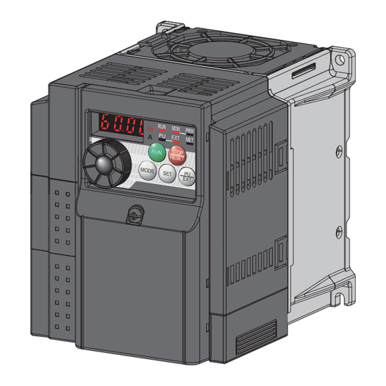
Page 64: Operation Panel
Operation panel Operation panel 4.1.1 Names and functions of the operation panel The operation panel cannot be removed from the inverter. Operation mode indication Operating status display ∗ Lit or flicker during inverter operation. Lit to indicate PU operation mode. EXT: Lit to indicate external operation * On: Indicates that... -
Page 65: Basic Operation (Factory Setting)
Operation panel 4.1.2 Basic operation (factory setting) Operation mode switchover At powering on (external operation mode) PU Jog operation mode (Example) PU operation mode Value change and frequency flicker. (output frequency monitor) Frequency setting has been written and completed!! STOP Output current monitor Output voltage monitor Display the... -
Page 66: Easy Operation Mode Setting (Easy Setting Mode)
Operation panel 4.1.3 Easy operation mode setting (easy setting mode) Setting of Pr. 79 Operation mode selection according to combination of the start command and speed command can be easily made. Changing Start command: external (STF/STR), frequency command: operate with example Operation Display... -
Page 67: Change The Parameter Setting Value
Operation panel 4.1.4 Change the parameter setting value Changing Change the Pr. 1 Maximum frequency setting. example Operation Display Screen at powering on The monitor display appears. PU indication is lit. Press to choose the PU operation mode. PRM indication is lit. Press to choose the parameter setting mode. -
Page 68: Parameter List
Parameter list Parameter list Parameter list 4.2.1 Parameter list For simple variable-speed operation of the inverter, the initial setting of the parameters may be used as they are. Set the necessary parameters to meet the load and operational specifications. Parameter setting, change and check can be made from the operation panel. -
Page 69: Parameter List
Parameter list Parameter list Control Mode-based Minimum Refer Instruction Code Parameter Func- Initial Customer Correspondence Table Parameter Name Setting Range Setting Parameter Remarks tion Value Setting Increments Page Read Write Extended Copy Clear All clear GP MFVC GP MFVC GP MFVC 110, —... - Page 70 Parameter list Parameter list Control Mode-based Minimum Refer Instruction Code Parameter Func- Initial Customer Correspondence Table Parameter Name Setting Range Setting Parameter Remarks tion Value Setting Increments Page Read Write Extended Copy Clear All clear GP MFVC GP MFVC GP MFVC Motor capacity 0.1 to 7.5kW, 9999 0.01kW...
- Page 71 Parameter list Parameter list Control Mode-based Minimum Refer Instruction Code Parameter Func- Initial Customer Correspondence Table Parameter Name Setting Range Setting Parameter Remarks tion Value Setting Increments Page Read Write Extended Copy Clear All clear GP MFVC GP MFVC GP MFVC Output current detection signal 0 to 10s, 9999 0.1s...
- Page 72 Parameter list Parameter list Control Mode-based Minimum Refer Instruction Code Parameter Func- Initial Customer Correspondence Table Parameter Name Setting Range Setting Parameter Remarks tion Value Setting Increments Page Read Write Extended Copy Clear All clear GP MFVC GP MFVC GP MFVC Life alarm status display (0 to 15) ×...
- Page 73 Parameter list Parameter list Control Mode-based Minimum Refer Instruction Code Parameter Func- Initial Customer Correspondence Table Parameter Name Setting Range Setting Parameter Remarks tion Value Setting Increments Page Read Write Extended Copy Clear All clear GP MFVC GP MFVC GP MFVC —...
- Page 74 — ∗1 Differ according to capacities. 6%: FR-D720-042 or less, FR-D740-022 or less, FR-D720S-042 or less 4%: FR-D720-070 to 165, FR-D740-036 to 080, FR-D720S-070 and 100 3%: FR-D720-238 and 318, FR-D740-120 and 160 ∗2 Differ according to capacities. 5s: FR-D720-165 or less, FR-D740-080 or less, FR-D720S-008 to 100 10s: FR-D720-238 and 318, FR-D740-120 and 160 ∗3...
-
Page 75: Adjust The Output Torque (Current) Of The Motor
Parameters according to purposes Adjust the output torque (current) of the motor 4.3.1 Manual torque boost (Pr. 0, Pr. 46) ....................73 4.3.2 Large starting torque and low speed torque are necessary (General-purpose magnetic flux vector control (Pr. 71, Pr. 80)) ......................... 75 4.3.3 Slip compensation (Pr. - Page 76 4.10.8 Remote output selection (REM signal, Pr. 495, Pr. 496) ............126 4.11 Monitor display and monitor output signal 4.11.1 Speed display and speed setting (Pr. 37)................... 127 4.11.2 Monitor display selection of operation panel/PU and terminal AM (Pr. 52, Pr.158, Pr. 170, Pr. 171, Pr. 268, Pr. 563, Pr. 564, Pr. 891) ......... 128 4.11.3 Reference of the terminal AM (analog voltage output) (Pr.
- Page 77 4.19.3 Operation selection at communication error occurrence (Pr. 121, Pr. 122, Pr. 502) ....184 4.19.4 Communication EEPROM write selection (Pr. 342) ..............187 4.19.5 Mitsubishi inverter protocol (computer link communication) ............188 4.19.6 Modbus RTU communication specifications (Pr. 117, Pr. 118, Pr. 120, Pr. 122, Pr. 343, Pr. 502, Pr. 549) ............ 200 4.20 Special operation and frequency control 4.20.1 PID control (Pr.
-
Page 78: Manual Torque Boost (Pr. 0, Pr. 46)
Initial Value Description Number Range FR-D720-042 or less FR-D740-022 or less FR-D720S-008 to 042 FR-D720-070 to 165 Torque boost 0 to 30% Set the output voltage at 0Hz as %. FR-D740-036 to 080 FR-D720S-070 and 100 FR-D720-238 and 318 FR-D740-120 and 160... - Page 79 Adjust the output torque (current) of the motor NOTE The amount of current flows in the motor may become large according to the conditions such as the motor characteristics, load, acceleration/deceleration time, wiring length, etc., resulting in an overcurrent trip (OL (overcurrent alarm) then E.OC1 (overcurrent trip during acceleration), overload trip (E.THM (motor overload trip), or E.THT (inverter overload trip).
-
Page 80: Large Starting Torque And Low Speed Torque Are Necessary (General-Purpose Magnetic Flux Vector Control (Pr. 71, Pr. 80))
Adjust the output torque (current) of the motor 4.3.2 Large starting torque and low speed torque are necessary (General-purpose magnetic flux vector control (Pr. 71, Pr. 80)) GP MFVC GP MFVC GP MFVC General-purpose magnetic flux vector control is available. Large starting torque and low speed torque are available with General-purpose magnetic flux vector control. - Page 81 Adjust the output torque (current) of the motor (2) Selection method of General-purpose magnetic flux vector control Perform secure wiring. (Refer to page 14) Display the extended function parameters. (Pr. 160) (Refer to page 162) Set "0" in Pr. 160 to display the extended function parameters. Set the motor.
- Page 82 Adjust the output torque (current) of the motor Control method switching by external terminals (X18 signal) Use the V/F switchover signal (X18) to change the control method (V/F control and General-purpose magnetic flux vector control) with external terminal. Turn the X18 signal on to change the currently selected control method (General-purpose magnetic flux vector control) to V/F control.
-
Page 83: Slip Compensation (Pr. 245 To Pr. 247)
Adjust the output torque (current) of the motor 4.3.3 Slip compensation (Pr. 245 to Pr. 247) Inverter output current may be used to assume motor slip to keep the motor speed constant. Parameter Name Initial Value Setting Range Description Number 0.01 to 50% Rated motor slip Rated slip... -
Page 84: Stall Prevention Operation (Pr. 22, Pr. 23, Pr. 48, Pr. 66, Pr. 156, Pr. 157)
Adjust the output torque (current) of the motor 4.3.4 Stall prevention operation (Pr. 22, Pr. 23, Pr. 48, Pr. 66, Pr. 156, Pr. 157) This function monitors the output current and automatically changes the output frequency to prevent the inverter from coming to trip due to overcurrent, overvoltage, etc. - Page 85 Adjust the output torque (current) of the motor (2) Setting of stall prevention operation level (Pr. 22) Pr. 22 Set in the percentage of the output current to the rated inverter current at which stall prevention operation will be Output current performed.
- Page 86 Adjust the output torque (current) of the motor Setting of stall prevention operation in high frequency range (Pr. 22, Pr. 23, Pr. 66) (Pr. 22 = 150%, Pr. 23 = 100%, Pr. 66 = 60Hz) Setting example Pr. 22 When Pr. 23 = 9999 When Pr.
- Page 87 Adjust the output torque (current) of the motor (6) Limit the stall prevention operation and fast-response current limit operation according to the operating status (Pr. 156) Refer to the following table and select whether stall prevention operation and fast-response current limit operation will be performed or not and the operation to be performed at OL signal output.
-
Page 88: Limit The Output Frequency
Limit the output frequency Limit the output frequency Purpose Parameter that should be Set Refer to Page Set upper limit and lower limit of Maximum/minimum Pr. 1, Pr. 2, Pr. 18 output frequency frequency Perform operation by avoiding Frequency jump Pr. -
Page 89: Avoid Mechanical Resonance Points (Frequency Jumps) (Pr. 31 To Pr. 36)
Limit the output frequency 4.4.2 Avoid mechanical resonance points (frequency jumps) (Pr. 31 to Pr. 36) When it is desired to avoid resonance attributable to the natural frequency of a mechanical system, these parameters allow resonant frequencies to be jumped. Parameter Name Initial Value... -
Page 90: Set V/F Pattern
Set V/F pattern Set V/F pattern Purpose Parameter that should be Set Refer to Page Base frequency, Set motor ratings Pr. 3, Pr. 19, Pr. 47 Base frequency voltage Select a V/F pattern according to Load pattern selection Pr. 14 applications. - Page 91 Set V/F pattern (3) Base frequency voltage setting (Pr. 19) Use Pr. 19 Base frequency voltage to set the base voltage (e.g. rated motor voltage). If the setting is less than the power supply voltage, the maximum output voltage of the inverter is as set in Pr. 19. Pr.
-
Page 92: Load Pattern Selection (Pr. 14)
Set V/F pattern 4.5.2 Load pattern selection (Pr. 14) Optimum output characteristic (V/F characteristic) for the application and load characteristics can be selected. Parameter Name Initial Value Setting Range Description Number For constant torque load For variable torque load For constant torque elevators Load pattern selection (at reverse rotation boost of 0%) For constant torque elevators... - Page 93 Set V/F pattern Constant-torque load application Pr. 14 = 3 Pr. 14 = 2 (setting "2, 3") For vertical lift loads For vertical lift loads Set "2" when a vertical lift load is fixed as power At forward rotation boost...Pr. 0 (Pr. 46) At forward rotation boost...0% At reverse rotation boost...Pr.
-
Page 94: Frequency Setting By External Terminals
Frequency setting by external terminals Frequency setting by external terminals Purpose Parameter that should be Set Refer to Page Make frequency setting by Pr. 4 to Pr. 6, Pr. 24 to Pr. 27, Multi-speed operation combination of terminals Pr. 232 to Pr. 239 Perform Jog operation Jog operation Pr. - Page 95 Frequency setting by external terminals (2) Multi-speed setting for 4th speed or more (Pr. 24 to Pr. 27, Pr. 232 to Pr. 239) Frequency from 4th speed to 15th speed can be set according to the combination of the RH, RM, RL and REX signals. Set the running frequencies in Pr.
-
Page 96: Jog Operation (Pr. 15, Pr. 16)
Frequency setting by external terminals 4.6.2 Jog operation (Pr. 15, Pr. 16) The frequency and acceleration/deceleration time for Jog operation can be set. Jog operation can be performed in either of the external and the PU operation mode. This operation can be used for conveyor positioning, test operation, etc. Parameter Initial Name... - Page 97 Frequency setting by external terminals (2) Jog operation from PU Selects Jog operation mode from the operation panel and PU (FR-PU04/FR-PU07). Operation is performed only while the start button is pressed. Inverter R/L1 Three-phase AC S/L2 Motor power supply T/L3 Operation panel Operation Display...
-
Page 98: Remote Setting Function (Pr. 59)
Frequency setting by external terminals NOTE When Pr. 29 Acceleration/deceleration pattern selection = "1" (S-pattern acceleration/deceleration A), the acceleration/ deceleration time is the period of time required to reach Pr. 3 Base frequency. The Pr. 15 setting should be equal to or higher than the Pr. 13 Starting frequency. The JOG signal can be assigned to the input terminal using any of Pr. - Page 99 Frequency setting by external terminals (1) Remote setting function Use Pr. 59 to select whether the remote setting function is used or not and whether the frequency setting storage function in the remote setting mode is used or not. When Pr. 59 is set to any of "1 to 3" (remote setting function valid), the functions of the RH, RM and RL signals are changed to acceleration (RH), deceleration (RM) and clear (RL).
- Page 100 Frequency setting by external terminals REMARKS During Jog operation or PID control operation, the remote setting function is invalid. Setting frequency is "0" Even when remotely-set frequency is cleared by turning on the RL (clear) signal after turn off Remotely-set frequency stored last time (on) of both the RH and RM signals, the inverter operates at Within 1 minute...
-
Page 101: Setting Of Acceleration/Deceleration Time And Acceleration/ Deceleration Pattern
Setting of acceleration/deceleration time and acceleration/ deceleration pattern Setting of acceleration/deceleration time and acceleration/ deceleration pattern Purpose Parameter that should be Set Refer to Page Motor acceleration/deceleration Acceleration/deceleration Pr. 7, Pr. 8, Pr. 20, Pr. 44, Pr. 45 time setting times Starting frequency and Starting frequency... - Page 102 Setting of acceleration/deceleration time and acceleration/ deceleration pattern Deceleration time setting (Pr. 8, Pr. 20) Use Pr. 8 Deceleration time to set the deceleration time required to reach 0Hz from Pr. 20 Acceleration/deceleration reference frequency. Set the deceleration time according to the following formula. Deceleration Pr.
-
Page 103: Starting Frequency And Start-Time Hold Function (Pr. 13, Pr. 571)
Setting of acceleration/deceleration time and acceleration/ deceleration pattern 4.7.2 Starting frequency and start-time hold function (Pr. 13, Pr. 571) You can set the starting frequency and hold the set starting frequency for a certain period of time. Set these functions when you need the starting torque or want to smooth motor drive at a start. Parameter Name Initial Value... -
Page 104: Acceleration/Deceleration Pattern (Pr. 29)
Setting of acceleration/deceleration time and acceleration/ deceleration pattern 4.7.3 Acceleration/deceleration pattern (Pr. 29) You can set the acceleration/deceleration pattern suitable for application. Parameter Name Initial Value Setting Range Description Number Linear acceleration/ deceleration Acceleration/deceleration S-pattern acceleration/deceleration A pattern selection S-pattern acceleration/deceleration B The above parameters can be set when Pr. -
Page 105: Selection And Protection Of A Motor
Selection and protection of a motor Selection and protection of a motor Purpose Parameter that should be Set Refer to Page Electronic thermal O/L relay Motor protection from overheat Pr. 9, Pr. 51, Pr. 561 PTC thermistor protection Use the constant torque motor Applied motor Pr. - Page 106 Selection and protection of a motor Set two different electronic thermal O/L relays (Pr. 51) Use this function when running two motors of different rated currents individually by a single inverter. (When running two motors together, use external thermal relays.) Set the rated current of the second motor to Pr.
- Page 107 Selection and protection of a motor (5) PTC thermistor protection (Pr. 561) Inverter Motor Terminal 2 and terminal 10 are available for inputting of motor built-in PTC thermistor output. When the PTC thermistor input reaches to the resistance value set in Pr. 561 PTC thermistor protection level, inverter outputs PTC thermistor operation error PTC thermistor input connection signal (E.PTC) and trips.
-
Page 108: Applied Motor (Pr. 71, Pr. 450)
Selection and protection of a motor 4.8.2 Applied motor (Pr. 71, Pr. 450) Setting of the used motor selects the thermal characteristic appropriate for the motor. Setting is required to use a constant-torque motor. Thermal characteristic of the electronic thermal relay function suitable for the motor is set. - Page 109 Selection and protection of a motor (2) Use two motors (Pr. 450) Set Pr. 450 Second applied motor to use two different motors with one inverter. When "9999" (initial value) is set, no function is selected. When a value other than 9999 is set in Pr. 450, the second motor is valid with the RT signal on. For the RT signal, set "3"...
-
Page 110: To Exhibit The Best Performance Of The Motor (Offline Auto Tuning) (Pr. 71, Pr. 80, Pr. 82 To Pr. 84, Pr. 90, Pr. 96)
Selection and protection of a motor 4.8.3 To exhibit the best performance of the motor (offline auto tuning) (Pr. 71, Pr. 80, Pr. 82 to Pr. 84, Pr. 90, Pr. 96) The motor performance can be maximized with offline auto tuning. What is offline auto tuning? When performing General-purpose magnetic flux vector control, the motor can be run with the optimum operating characteristics by automatically measuring the motor constants (offline auto tuning) even when each motor constants... - Page 111 Selection and protection of a motor (1) Before performing offline auto tuning Check the following before performing offline auto tuning. Make sure General-purpose magnetic flux vector control (Pr. 80) is selected. (Tuning can be performed even under V/F control selected by turning on X18.) A motor should be connected.
- Page 112 Selection and protection of a motor Execution of tuning POINT Before performing tuning, check the monitor display of the operation panel or parameter unit (FR-PU04/FR-PU07) if the inverter is in the status for tuning. (Refer to 2) below) When the start command is turned on under V/F control, the motor starts.
- Page 113 Selection and protection of a motor 3) When offline auto tuning ends, press of the operation panel during PU operation. For external operation, turn OFF the start signal (STF signal or STR signal) once. This operation resets the offline auto tuning and the PU's monitor display returns to the normal indication. (Without this operation, next operation cannot be started.) 4) If offline auto tuning ended in error (see the table below), motor constants are not set.
-
Page 114: Motor Brake And Stop Operation
Motor brake and stop operation Motor brake and stop operation Purpose Parameter that should be Set Refer to Page Motor braking torque adjustment DC Injection brake Pr. 10 to Pr. 12 Improve the motor braking torque with Selection of a Pr. -
Page 115: Selection Of A Regenerative Brake (Pr. 30, Pr. 70)
Motor brake and stop operation REMARKS For the FR-D720-238 and 318, FR-D740-120 and 160, when the Pr. 12 setting is the following, changing the Pr. 71 Applied motor setting automatically changes the Pr. 12 setting. Therefore, it is not necessary to change the Pr. 12 setting. (a) When 4% (initial value) is set in Pr. - Page 116 Motor brake and stop operation When using the high-duty brake resistor (FR-ABR) (FR-D720-025 or more, FR-D740-012 or more, FR- D720S-025 or more) Set "1" in Pr. 30. Set "10%" in Pr. 70. When a high power factor converter (FR-HC) is used and automatic restart after instantaneous power failure function is valid.
-
Page 117: Stop Selection (Pr. 250)
Motor brake and stop operation 4.9.3 Stop selection (Pr. 250) Used to select the stopping method (deceleration to a stop or coasting) when the start signal turns OFF. Used to stop the motor with a mechanical brake, etc. together with switching OFF of the start signal. You can also select the operations of the start signals (STF/STR). -
Page 118: 4.10 Function Assignment Of External Terminal And Control
Function assignment of external terminal and control 4.10 Function assignment of external terminal and control Purpose Parameter that should be Set Refer to Page Input terminal function Assign function to input terminal Pr. 178 to Pr. 182 selection Set MRS signal (output shutoff) to MRS input selection Pr. - Page 119 Function assignment of external terminal and control (1) Input terminal function assignment Using Pr. 178 to Pr. 182, set the functions of the input terminals. Refer to the following table and set the parameters: Refer to Setting Signal Function Related Parameters Page Pr.
-
Page 120: Inverter Output Shutoff Signal (Mrs Signal, Pr. 17)
Function assignment of external terminal and control 4.10.2 Inverter output shutoff signal (MRS signal, Pr. 17) The inverter output can be shut off by the MRS signal. Also, logic for the MRS signal can be selected. Parameter Name Initial Value Setting Range Description Number... -
Page 121: Condition Selection Of Function Validity By Second Function Selection Signal (Rt)
Function assignment of external terminal and control 4.10.3 Condition selection of function validity by second function selection signal (RT) You can select the second function using the RT signal. When the RT signal turns ON, the second function becomes valid. For the RT signal, set "3"... -
Page 122: Start Signal Operation Selection (Stf, Str, Stop Signal, Pr. 250)
Function assignment of external terminal and control 4.10.4 Start signal operation selection (STF, STR, STOP signal, Pr. 250) You can select the operation of the start signal (STF/STR). Used to select the stopping method (deceleration to a stop or coasting) when the start signal turns OFF. Used to stop the motor with a mechanical brake, etc. - Page 123 Function assignment of external terminal and control (2) Three-wire type (STF, STR, STOP signal) The three-wire connection is shown below. Turning the STOP signal ON makes start self-holding function valid. In this case, the forward/reverse rotation signal functions only as a start signal. If the start signal (STF or STR) is turned ON and then OFF, the start signal is held and makes a start.
-
Page 124: Output Terminal Function Selection (Pr. 190, Pr. 192)
Function assignment of external terminal and control 4.10.5 Output terminal function selection (Pr. 190, Pr. 192) You can change the functions of the open collector output terminal and relay output terminal. Parameter Initial Name Initial Signal Setting Range Number Value 0, 1, 3, 4, 7, 8, 11 to 16, 25, 26, RUN terminal Open collector... - Page 125 Function assignment of external terminal and control Setting Refer Related Signal Function Operation Positive Negative Parameter Page logic logic Output when any of the control circuit capacitor, main Pr. 255 to Life alarm circuit capacitor and inrush current limit circuit or the Pr.
- Page 126 Function assignment of external terminal and control Inverter operation ready signal (RY signal) and inverter running signal (RUN signal) Power supply DC injection brake operation point DC injection brake operation Pr. 13 Starting frequency Time Reset processing When the inverter is ready to operate, the output of the operation ready signal (RY) is ON. (It is also ON during inverter running.) When the output frequency of the inverter rises to or above Pr.
- Page 127 Function assignment of external terminal and control (3) Fault output signal (ALM signal) Inverter fault occurrence If the inverter comes to trip, the ALM signal is output. (Trip) Output frequency Time ON OFF Reset processing (about 1s) Reset ON REMARKS The ALM signal is assigned to the ABC contact in the initial setting.
-
Page 128: Detection Of Output Frequency (Su, Fu Signal, Pr. 41 To Pr. 43)
Function assignment of external terminal and control 4.10.6 Detection of output frequency (SU, FU signal, Pr. 41 to Pr. 43) The inverter output frequency is detected and output at the output signals. Parameter Name Initial Value Setting Range Description Number Up-to-frequency 0 to 100% Level where the SU signal turns ON. -
Page 129: Output Current Detection Function (Y12 Signal, Y13 Signal, Pr. 150 To Pr. 153, Pr. 166, Pr. 167)
Function assignment of external terminal and control 4.10.7 Output current detection function (Y12 signal, Y13 signal, Pr. 150 to Pr. 153, Pr. 166, Pr. 167) The output current during inverter running can be detected and output to the output terminal. Parameter Setting Name... - Page 130 Function assignment of external terminal and control Zero current detection (Y13 signal, Pr. 152, Pr. 153) If the output current remains lower than the Pr. 152 setting during inverter operation for longer than the time set in Pr. 153, the zero current detection (Y13) signal is output from the inverter's open collector or relay output terminal.
Need help?
Do you have a question about the FR-D720-070 and is the answer not in the manual?
Questions and answers