Table of Contents
Advertisement
MITSUBISHI
ELECTRIC
INVERTER
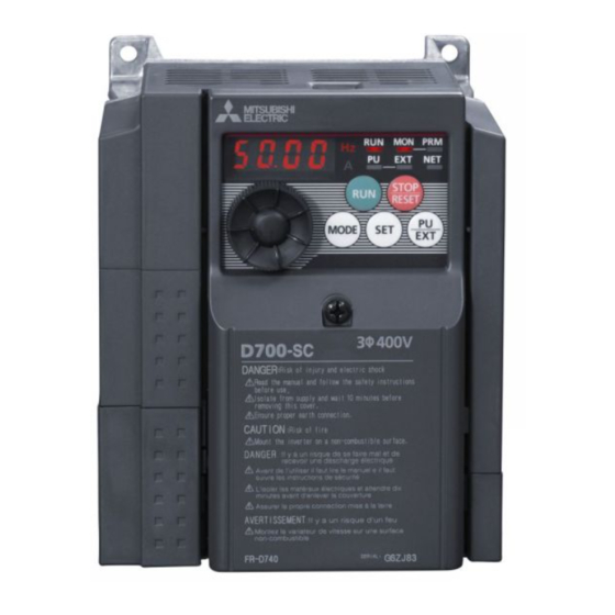
FR-D700 SC
INSTALLATION GUIDELINE
FR-D720S-008SC to 100SC-EC
FR-D740-012SC to 160SC-EC
Thank you for choosing this Mitsubishi Electric inverter.
Please read through this Installation Guideline and the enclosed CD ROM to operate this inverter
correctly.
Do not use this product until you have a full knowledge of the equipment, the safety information and the
instructions.
Please forward this Installation Guideline and the CD ROM to the end user.
PRODUCT DESCRIPTION ................................................................................................... 1
1
INSTALLATION OF THE INVERTER AND INSTRUCTIONS................................................. 2
2
OUTLINE DIMENSION DRAWING ...................................................................................... 4
3
WIRING ............................................................................................................................... 5
4
PRECAUTIONS FOR USE OF THE INVERTER ................................................................... 13
5
FAILSAFE OF THE SYSTEM WHICH USES THE INVERTER .............................................. 15
6
PARAMETER ..................................................................................................................... 16
7
TROUBLESHOOTING........................................................................................................ 21
8
MAINTENANCE AND INSPECTION .................................................................................. 24
9
SPECIFICATIONS .............................................................................................................. 25
10
Art. no.: 260530
14 02 2013
Version A
Version check
CONTENTS
700
ORIGINAL INSTRUCTION
Advertisement
Table of Contents

Subscribe to Our Youtube Channel
Related Manuals for Mitsubishi Electric FR-D720S-008SC


Summary of Contents for Mitsubishi Electric FR-D720S-008SC
-
Page 1: Table Of Contents
INSTALLATION GUIDELINE FR-D720S-008SC to 100SC-EC FR-D740-012SC to 160SC-EC Thank you for choosing this Mitsubishi Electric inverter. Please read through this Installation Guideline and the enclosed CD ROM to operate this inverter correctly. Do not use this product until you have a full knowledge of the equipment, the safety information and the instructions. - Page 2 First edition For Maximum Safety Mitsubishi Electric transistorized inverters are not designed or manufactured to be used in equipment or systems in situations that can affect or endanger human life. When considering this product for operation in special applications such as machinery or systems used in passenger transportation, medical, aerospace, atomic power, electric power, or submarine repeating applications, please contact your nearest Mitsubishi Electric sales representative.
- Page 3 Inverter FR-D700 SC Safety stop function Instruction Manual". Mitsubishi Electric Co. accepts no claims for liability if the equipment is used in any other way or if modifications are made to the device, even in the context of mounting and installation.
- Page 4 General Protective Notes and Protective Measures Observe the protective notes and measures! Please observe the following items in order to ensure proper use of the FR-D700 SC inverter. When mounting, installing and using the FR-D700 SC inverter, observe the standards and directives applicable in your country. The national rules and regulations apply to the installation, use and periodic technical inspection of the FR-D700 SC, in particular: –...
- Page 5 Do not install assemblies or components (e. g. power factor correction capacitors) on the inverter output side, which are not approved from Mitsubishi Electric. The direction of rotation of the motor corresponds to the direction of rotation commands (STF/STR) only if the phase sequence (U, V, W) is maintained.
- Page 6 CAUTION The electronic thermal relay function does not guarantee protection of the motor from overheating. It is recommended to install both an external thermal and PTC thermistor for overheat protection. Do not use a magnetic contactor on the inverter input for frequent starting/stopping of the inverter. Otherwise, the life of the inverter decreases.
-
Page 7: Product Description
1 PRODUCT DESCRIPTION 1.1 FR-D700 SC Inverter An FR-D700 SC frequency inverter is a device that converts the fixed voltage and frequency of the mains power supply into a variable voltage with a variable frequency. It is installed between the mains supply and the motor and makes continuously-variable speed adjustment possible. -
Page 8: Installation Of The Inverter And Instructions
2 INSTALLATION OF THE INVERTER AND INSTRUCTIONS Unpack the inverter and check the capacity plate on the front cover and the rating plate on the inverter side face to ensure that the product agrees with your order and the inverter is intact. 2.1 Inverter Type FR - D740 - 036 SC - EC Symbol... -
Page 9: Installation Of The Inverter
INSTALLATION OF THE INVERTER AND INSTRUCTIONS 2.4 Installation of the Inverter Enclosure surface mounting Remove the front cover and wiring cover to fix the inverter to the surface. FR-D720S-008SC to 042SC FR-D720S-070SC and 100SC, FR-D740-012SC to 160SC Front cover Front cover... -
Page 10: Outline Dimension Drawing
3 OUTLINE DIMENSION DRAWING 2-ØC hole 1-ØC hole (Unit: mm) Inverter Type FR-D720S-008SC 80.5 FR-D720S-014SC FR-D720S-025SC 142.5 FR-D720S-042SC 162.5 FR-D720S-070SC 155.5 FR-D720S-100SC FR-D740-012SC 129.5 FR-D740-022SC FR-D740-036SC 135.5 FR-D740-050SC 155.5 FR-D740-080SC 165.5 FR-D740-120SC FR-D740-160SC... -
Page 11: Wiring
4.1 Terminal Connection Diagram Source logic *1 DC reactor Main circuit terminal When connecting a DC reactor, remove the *6 FR-D720S-008SC to 100SC: +, – jumper across P1 and P/+. FR-D740-012SC to 160SC: P/+, N/– Control circuit terminal Single-phase power input... -
Page 12: Main Circuit Terminal Specifications
The output of the single-phase power input specification is three-phase 230 V. 4.2 Main Circuit Terminal Specifications 4.2.1 Terminal Arrangement of the Main Circuit Terminal, Power Supply and the Motor Wiring Single-Phase 200 V Class FR-D720S-008SC to 042SC FR-D720S-070SC and 100SC Jumper Jumper... -
Page 13: Cables And Wiring Length
Single-phase 200 V class (when input power supply is 220 V) Crimping Terminal Applicable Inverter Type Tightening Torque [Nm] Terminal Screw Size L1, N, P1, + U, V, W FR-D720S-008SC to 042SC M3.5 2-3.5 2-3.5 FR-D720S-070SC FR-D720S-100SC 5.5-4 Cable Sizes... - Page 14 Limiting the voltage rise speed of the frequency inverter output voltage (dV/dT): If the motor requires a rise speed of 500 V/μs or less you must install a filter in the output of the inverter. Please contact your Mitsubishi Electric dealer for more details. CAUTION...
-
Page 15: Control Circuit Terminal Layout
WIRING 4.4 Control Circuit Specification 4.4.1 Terminal Assignment Input Signal Output Signal Type Terminal Name Type Terminal Name Forward rotation start Relay A, B, C Relay output (alarm output) Contact input Reverse rotation start Inverter running RH, RM, RL Multi-speed selection Open collector Open collector output common Contact input common (sink),... -
Page 16: Wiring Method
WIRING 4.4.3 Wiring Method Use a bar terminal and a cable with a sheath stripped off for the control circuit wiring. For a single wire, strip off the sheath of the cable and apply directly. Insert the bar terminal or the single wire into a socket of the terminal. Strip off the sheath about the length below. -
Page 17: Wiring Instructions
WIRING Insert the wire into a socket. When using a single wire or a stranded wire without a bar terminal, push an open/close button all the way down with a flathead screw driver, and insert the wire. Open/close button Flathead screwdriver CAUTION When using a stranded wire without a bar terminal, twist enough to avoid short circuit with a nearby terminals or wires. - Page 18 WIRING 4.4.5 Safety Stop Function Connection Diagram for Intended Use This diagram shows the example connection diagram for intended use. The safety relay module is necessary for the generating redundant safe stop signals which are connected to the S1 and S2 terminal of FR-D700 SC.
-
Page 19: Precautions For Use Of The Inverter
Across P/+ and PR terminals, connect only an external regenerative brake discharge resistor. Do not connect a mechanical brake. The brake resistor can not be connected to the FR-D720S-008SC and 014SC. Leave terminals P/+ and PR open. Also, never short between P/+ and PR. - Page 20 PRECAUTIONS FOR USE OF THE INVERTER Do not apply a voltage higher than the permissible voltage to the inverter I/O signal circuits. Application of a voltage higher than the permissible voltage to the inverter I/O signal circuits or opposite polarity may damage the I/O devices.
-
Page 21: Failsafe Of The System Which Uses The Inverter
When a fault occurs, the inverter trips to output a fault signal. However, a fault output signal may not be output at an inverter fault occurrence when the detection circuit or output circuit fails, etc. Although Mitsubishi Electric assures best quality products, provide an interlock which uses inverter status output signals to prevent accidents such as damage to machine when the inverter fails for some reason. -
Page 22: Parameter
6 %: FR-D720S-042SC or less, FR-D740-022SC or less 4 %: FR-D720S-070SC and 100SC, FR-D740-036SC to 080SC 3 %: FR-D740-120SC and 160SC Differs according to capacities. 5 s: FR-D720S-008SC to 100SC, FR-D740-080SC or less 10 s: FR-D740-120SC and 160SC Differs according to capacities. 6 %: FR-D720S-008SC and 014SC... - Page 23 PID control automatic switchover 0 to 400 Hz, 9999 9999 frequency Differs according to capacities. 5 s: FR-D720S-008SC to 100SC, FR-D740-080SC or less 10 s: FR-D740-120SC and 160SC The initial value differs according to the voltage class: 200 V/400 V...
- Page 24 PARAMETER Parameter Name Setting Range Initial Value Parameter Name Setting Range Initial Value 0, 20, 21, 0 to 5, 7, 8, 10, 12, PID action selection STR terminal function 40 to 43 14, 16, 18, 24, 25, 37, 61, 62, 65 to selection 0.1 to 1000 %, PID proportional band...
- Page 25 PARAMETER Parameter Name Setting Range Initial Value Parameter Name Setting Range Initial Value Control circuit Current average time 0.1 to 1 s (0 to 100 %) 100 % capacitor life display Data output mask time 0 to 20 s Main circuit capacitor (0 to 100 %) 100 % Current average value...
- Page 26 PARAMETER Parameter Name Setting Range Initial Value Parameter Name Setting Range Initial Value Free parameter 2 0 to 9999 9999 Terminal 4 frequency 0 to 400 Hz 50 Hz setting gain frequency (905) Cumulative power monitor digit shifted 0 to 4, 9999 9999 Terminal 4 frequency times...
-
Page 27: Troubleshooting
8 TROUBLESHOOTING The frequency inverter FR-D700 SC has a multitude of protective functions which protect the drive and the inverter from damage in case of a fault. When a fault occurs in the inverter, the protective function is activated bringing the inverter to an alarm stop and the PU display automatically changes to any of the following fault (alarm) indications. -
Page 28: Reset Method Of Protective Function
TROUBLESHOOTING 8.1 Reset Method of Protective Function Resetting the Inverter The inverter can be reset by performing any of the following operations. Note that the internal thermal integrated value of the electronic thermal relay function and the number of retries are cleared (erased) by resetting the inverter. Inverter recovers about 1s after reset is cancelled. -
Page 29: List Of Alarm Display
TROUBLESHOOTING 8.2 List of Alarm Display Operation Panel Indication Meaning Operation Panel Indication Meaning E - - - Faults history E.ILF* Input phase loss HOLD Operation panel lock E.OLT Stall prevention E.BE Brake transistor alarm detection Er1 to 4 Parameter write error Output side earth (ground) fault E.GF overcurrent protection... -
Page 30: Maintenance And Inspection
9 MAINTENANCE AND INSPECTION 9.1 Daily Inspection Followings are the daily checking points during operation: Rotation speed of motor Environmental condition of the inverter drive Activation of cooling system Extraordinary vibration or airborne noise Over heating or discoloration For detailed checking operation please refer to the Instruction manual of FR-D700 SC. 9.2 Periodic Inspection It is recommended to make the following checks periodically: Check for loose screws in the terminal block. -
Page 31: Specifications
Weight [kg] The applied motor capacity indicated is the maximum capacity applicable for use of the Mitsubishi Electric 4-pole standard motor. The rated output capacity indicated assumes that the output voltage is 230 V/440 V (200 V class/400 V class). -
Page 32: Aappendix
EMC Directive and the Low Voltage Directive, the manufacturer must declare the conformity and affix the CE marking. The authorized representative in the EU Name: Mitsubishi Electric Europe B.V. Address: Gothaer Strasse 8, 40880 Ratingen, Germany NOTE We declare that this inverter, when equipped with the dedicated EMC filter, conforms with the EMC Directive in industrial environments and affix the CE marking on the inverter. - Page 33 APPENDIX A.1.2 Low Voltage Directive We have self-confirmed our inverters as products compliant to the Low Voltage Directive (conforming standard EN 61800-5-1) and placed the CE mark on the inverters. Outline of Instructions If your application requires by installation standards an RCD (residual current device) as up stream protection please select according to DIN VDE 0100-530 as following: Single phase inverter type A or B Three phase inverter only type B.
- Page 34 (Pr. 9 = 0 (A)) current. It is not the percentage to the motor rated current. When you set the electronic thermal relay function dedicated to the Mitsubishi Electric constant-torque motor, this characteristic curve applies to operation at 6 Hz or higher. Region for...
- Page 35 APPENDIX CAUTION Protective function by electronic thermal relay function is reset by inverter power reset and reset signal input. Avoid unnecessary reset and power-OFF. Install an external thermal relay (OCR) between the inverter and a motor when operating several motors by one inverter, or when using a multi-pole motor or special motor.
- Page 36 APPENDIX A.2 Instructions for UL and cUL (UL 508C, CSA C22.2 No.14) A.2.1 General Precaution The bus capacitor discharge time is 10 minutes. Before starting wiring or inspection, switch power off, wait for more than 10 minutes, and check for residual voltage between terminal P/+ and N/ with a meter etc., to avoid a hazard of electrical shock. A.2.2 Environment Before installation, check that the environment meets following specifications: Enclosure...
- Page 37 APPENDIX...
- Page 38 Phone: +370 (0)5 / 232 3101 Fax: +380 (0)44 / 494-33-66 Fax: +370 (0)5 / 232 2980 Mitsubishi Electric Europe B.V. /// FA - European Business Group /// Gothaer Straße 8 /// D-40880 Ratingen /// Germany Tel.: +49(0)2102-4860 /// Fax: +49(0)2102-4861120 /// info@mitsubishi-automation.com /// www.mitsubishi-automation.com...
Need help?
Do you have a question about the FR-D720S-008SC and is the answer not in the manual?
Questions and answers