Sign In
Upload
Download
Table of Contents
Contents
Add to my manuals
Delete from my manuals
Share
URL of this page:
HTML Link:
Bookmark this page
Add
Manual will be automatically added to "My Manuals"
Print this page
×
Bookmark added
×
Added to my manuals
Manuals
Brands
Projecta Manuals
Battery Charger
IC2500L
User manual
Projecta IC2500L User Manual
Intelli-charge lithium battery charger
Hide thumbs
1
2
3
4
5
6
7
8
9
10
11
12
13
14
15
16
17
18
19
20
Table Of Contents
21
page
of
21
Go
/
21
Contents
Table of Contents
Bookmarks
Table of Contents
Battery Charger
Important Safety Information
Soft Start
Remote Control Display
Temperature Compensation
Mounting Instructions
Mounting Battery Charger
Flush Mount
Surface Mount
Charging Instructions
Step 4 - Set Charge Rate
Step 5 - Charge Mode
Specifications
Product Overview
Frequently Asked Questions
Warranty Statement
Important Note
Advertisement
Quick Links
1
Battery Charger
2
Charging Instructions
3
Step 4 - Set Charge Rate
4
Step 5 - Charge Mode
5
Specifications
6
Frequently Asked Questions
Download this manual
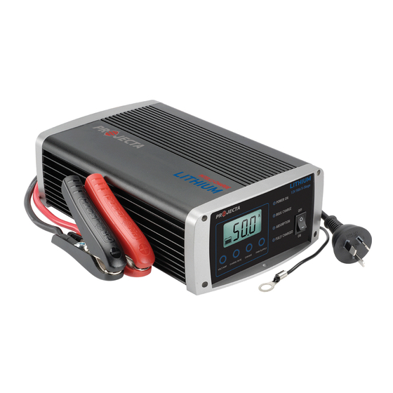
INTELLI-CHARGE LITHIUM
BATTERY CHARGER
5 STAGE SWITCHMODE
P/No.s IC2500L, IC5000L
Table of
Contents
Previous
Page
Next
Page
1
2
3
4
5
Advertisement
Table of Contents
Need help?
Do you have a question about the IC2500L and is the answer not in the manual?
Ask a question
Questions and answers
Related Manuals for Projecta IC2500L
Battery Charger Projecta IC1000 User Manual
Intelli-charge 12 volt, 7 stage switchmode battery charger (17 pages)
Battery Charger Projecta IC700 User Manual
Intelli-charge 12 volt, 7 stage switchmode battery charger (17 pages)
Battery Charger Projecta IC1500 User Manual
Intelli-charge 12 volt, 7 stage switchmode battery charger (17 pages)
Battery Charger Projecta IC2500 User Manual
7 stage switchmode (25 pages)
Battery Charger Projecta IC5000 User Manual
7 stage switchmode (25 pages)
Battery Charger Projecta IC800-24 User Manual
7 stage switchmode (25 pages)
Battery Charger Projecta IC3500 User Manual
7 stage switchmode (25 pages)
Battery Charger Projecta IC5000L User Manual
Intelli-charge lithium battery charger (21 pages)
Battery Charger Projecta IC1500L Manual
Lithium 12 volt, 5 stage switchmode battery charger (17 pages)
Battery Charger Projecta INTELLI-CHARGE IC25 Manual
7 stage switchmode (25 pages)
Battery Charger Projecta INTELLI-CHARGE IC8-24 Manual
7 stage switchmode (25 pages)
Battery Charger Projecta INTELLI-CHARGE IC7 Manual
12 volt, 7 stage switchmode (21 pages)
Battery Charger Projecta IC100L Instruction Manual
Intelli-charge lithium 12 volt, 5 stage switchmode battery charger (13 pages)
Battery Charger Projecta IDC25 User Manual
Dc/solar battery charger (17 pages)
Battery Charger Projecta INVCHR2 Manual
Intelli-grid 12v inverter charger (20 pages)
Battery Charger Projecta INVCHRD-BT Quick Start Manual
Inverter charger battery monitor (8 pages)
This manual is also suitable for:
Ic5000l
Table of Contents
Print
Rename the bookmark
Delete bookmark?
Delete from my manuals?
Login
Sign In
OR
Sign in with Facebook
Sign in with Google
Upload manual
Upload from disk
Upload from URL


Need help?
Do you have a question about the IC2500L and is the answer not in the manual?
Questions and answers