YOKOGAWA 240413, 240415, 240414, 240416 - Insulation Tester Manual
- User manual (2 pages)
Advertisement
GENERAL
Description
Periodically testing of the insulation resistance of electrical machines, power distribution lines, communication cables and other electric devices, helps to locate faults before they become serious.
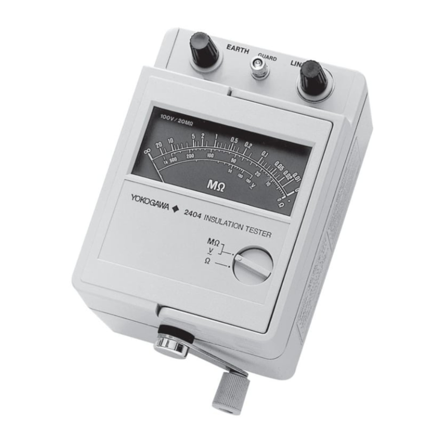
The 2404 Insulation Tester is a hand-driven type insulation resistance tester incorporating a built-in generator and a constant DC voltage circuit to provide a stable output and give a direct resistance reading. The insulation resistance is indicated on a moving coil type indicator with a logarithmic scale. Not only insulation resistance testing and AC voltage measurement, but also general continuity testing and low resistance measurement are possible using the 500Ω full scale low resistance measuring range of the instrument (not on Models 240415, 240416). The black indicator scale is easy-to-read. This insulation tester is ruggedly built and uses a shock-and heat-resistant polycarbonate resin case.
Specifications
| Item | Specifications | ||
| Model | Insulation Resistance Rated Voltage/Rated Resistance | Ac Voltage Measuring Range | Low Resistance Measuring Range (continuity test range) |
| 240413 240414 240415 240416 | 500 V/ 100 MΩ 500 V/ 1000 MΩ 1000 V/ 2000 MΩ 2000 V/ 5000 MΩ | 0 to 300 V 0 to 300 V 0 to 300 V 0 to 300 V | 0 to 500 Ω (central scale mark 50Ω) 0 to 500 Ω (central scale mark 50Ω) ____ (See Note 1) ____ |
| Accuracy | ±5% of indicated value in Effective Measuring Range 1 (See Note 2), ±10% of indicated value in Effective Measuring Range 2 (See Note 2) Less than 0.7% of scale length at zero and infinity scale marks. AC Voltage Measurement: ±10%of full scale. | ||
| Measuring Terminal Voltage | Accuracy: ±10% of rated voltage at infinity scale mark, or more than 90% of rated voltage at center scale mark. | ||
| Rotational Speed of Crank | More than 120 rpm. | ||
| Case Material | Polycarbonate resin. | ||
| Dimensions | Approx. 184x112x105 mm (7-1 /4x4-3/8x4-1 /8") | ||
| Weight | Approx. 1.3 kg(2.9 lbs) | ||
| Accessories Supplied at No Extra Cost | User's Manual Spare Fuse (2 pcs installed), Carrying Case | ||
- Optional Accessories Available,
Measuring leadwires B9634FA - Spare Part
Fuse (0.1 A)
Note 1: The center scalemark is the scale position of 1, 2, 5 or multiples of 10 there of and corresponds to a value of approximately onefiftieth the rated resistance.
Note 2: Effective Measuring Range 1 extends from 1/1000 of the rated resistance to the center scale mark at 1, 2, 5 or multiples of 10 there of which most nearly correspond to 1/2 of the rated resistance.
Effective measuring range 2 extends from the upper limit of effective measuring range 1 to the rated resistance value.

NAMES AND FUNCTIONS OF COMPONENTS

- Function Select Switch:
Insulation and AC voltage measurements (MΩ and V) and resistance Test (Ω) can be selected with this switch. (except Models 240415, 240416) - LINE Terminal:
To measure Insulation resistance, AC voltage and resistance use this LINE terminal and the EARTH terminal (3) below. - EARTH (ground) Terminal
- GUARD Terminal
- Crank
- Carrying Handle
OPERATION
AC Voltage Measurement
- Power line AC voltages can be measured using this tester. Always prior to an insulation resistance measurement, use the tester to check whether the object to be measured is live or not.
- Connect measuring lead wires to the LINE and EARTH terminals. Use optional accessoryB9634FA measuring leadwires or equivalent high insulation resistance leadwires.
- Place the instrument on a fairly level surface with the crank facing you. Turn the carryinghandle down.
- Set the function select switch to V. Prior to connecting an object for an AC voltagemeasurement, short-circuit the tester LINE and EARTH lead wires. Turn the crank to check to see that the indicator shows zero ohms. This confirms that the tester is operating normally.
- To make a voltage measurement touch the LINE and EARTH lead wires to the line to bemeasured and read the indication on the "AC V" scale as you would read in ordinary voltmeter.
During voltage measurement, do not turn the crank.
Insulation Resistance Measurement
- Read the NOTE below, then connect the object to be measured between the LINE and EARTHterminals. Set the function select switch to MΩ.
- Turn the crank at a speed of more than 120 rpm to obtain a constant voltage output. The pointerwill indicate the measured insulation resistance value.
*Crank rotation may be either clockwise or counterclockwise. - While turning the crank, read the pointer indication.

- When one side of the measured circuit is grounded, connect the earth side to the EARTH terminal (positive side) of the tester. Normally, this connection gives smaller (conservative) values of insulation resistance, to be on the safe side. In this case, the lead-wires connected to the LINE terminal (negative side) should be kept always from earth and other objects.
- When the measured circuit is not grounded, it may be connected to either LINE or EARTHterminal.
- The GUARD terminal is used only when volume resistance is to be measured without beinginfluenced by surface leakage resistance. For example, when the insulation test is conducted on a cable such as shown in Figure 3-1, wind a bare wire around the insulating material and connect this wire to the GUARD terminal. In this arrangement, the leakage current flowing on the surface of the insulating material will not pass through the indicator. Thus, only the volume resistance is measured.


Low Resistance Measurement
Set the function select switch to Ω. Connect the object at be measured between the LINE and EARTH leadwires. Turn the Crank at a speed of more than 120 rpm and read the indication on the "Ω" scale. Low resistance measurement cannot be made using the Models 240415 (1000 V/ 2000 MΩ) and 240416 (2000 V/5000 MΩ) insulation testers.
- Be sure not to apply a voltage between the terminals during low resistance measurement.
- If power line AC voltage is applied to the instrument in error while on the low resistance range, the instrument is protected by an internal fuse. If the fuse is blown, replace it according of the procedure as described in paragraph 4.2. Insulation resistance and AC voltage can be measured normally even when the fuse is blown.
- If the fuse is blown, the pointer points to the "*" mark during low resistance measurement. (See Figure 3-2)
- The 1k mark on the Ω scale is not accurate and may be considered as being "off scale". Note that there is no resistance scale mark for Rx = ∞ (when test probes are not connected to anything).
![]()

MAINTENANCE
Storage
When storing the Insulation Tester, avoid area which is:
- Very humid.
- Subject to direct sunlight.
- Near high temperature heat sources.
- Subject to strong vibration.
- Very dusty, or contains corrosive gases.
Fuse Replacement
If the fuse is blown during the low resistance measurement, replace the fuse as follows. Remove two case fixing screws on the bottom of the instrument. Then the instrument can be disassembled into two parts as shown in Figure 4-1. Replace the fuse on the printed circuit board with a spare fuse (0.1 A). Two spare fuses are installed inside the instrument case.

- Notice Regarding This Manual
- The contents of this manual are subject to change without prior notice.
- If any questions arise or errors are found, or if any information is missing from this manual, please inform Yokogawa.
- Yokogawa is by no means liable for damage resulting from the misuse of this product by the user.
- This manual is intended to explain the functions of this product Yokogawa does not warrant that the functions will suit a particular purpose of the user.
International Sales Dept.
Tachihi Bld. No.2, 6-1-3, Sakaecho, Tachikawa-shi, Tokyo 190-8586 Japan
Phone: 81-42-534-1413, Facsimile: 81-42-534-1426
YOKOGAWA CORPORATION OF AMERICA (U.S.A.)
Phone: 1-770-253-7000 Facsimile: 1-770-251-2088
YOKOGAWA EUROPE B. V. (THE NETHERLANDS)
Phone: 31-334-64-1611 Facsimile: 31-334-64-1610
YOKOGAWA ENGINEERING ASIA PTE. LTD. (SINGAPORE)
Phone: 65-6241-9933 Facsimile: 65-6241-2606
YOKOGAWA AMERICA DO SUL S. A. (BRAZIL)
Phone: 55-11-5681-2400 Facsimile: 55-11-5681-1274
YOKOGAWA MEASURING INSTRUMENTS KOREA CORPORATION (KOREA)
Phone: 82-2-551-0660 to -0664 Facsimile: 82-2-551-0665
YOKOGAWA AUSTRALIA PTY. LTD. (AUSTRALIA)
Phone: 61-2-9805-0699 Facsimile: 61-2-9888-1844
YOKOGAWA INDIA LTD. (INDIA)
Phone: 91-80-4158-6000 Facsimile: 91-80-2852-1441
YOKOGAWA SHANGHAI TRADING CO., LTD. (CHINA)
Phone: 86-21-6880-8107 Facsimile: 86-21-6880-4987
YOKOGAWA MIDDLE EAST E. C. (BAHRAIN)
Phone: 973-358100 Facsimile: 973-336100

Documents / ResourcesDownload manual
Here you can download full pdf version of manual, it may contain additional safety instructions, warranty information, FCC rules, etc.
Download YOKOGAWA 240413, 240415, 240414, 240416 - Insulation Tester Manual
Advertisement


Need help?
Do you have a question about the 240413 and is the answer not in the manual?
Questions and answers