Table of Contents
Advertisement
Quick Links
Advertisement
Table of Contents

Related Manuals for YOKOGAWA DLM4000 Series


Summary of Contents for YOKOGAWA DLM4000 Series
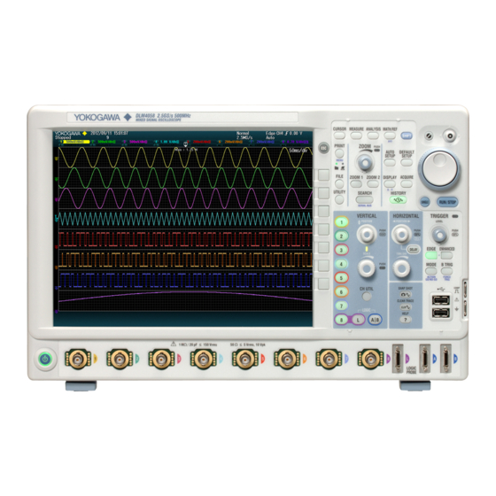
- Page 1 DLM4000 Series Mixed Signal Oscilloscope IM DLM4038-02EN 7th Edition...
- Page 2 Keep this manual in a safe place for quick reference in the event that a question arises. List of Manuals The following manuals, including this one, are provided as manuals for the DLM4000 series. Please read all manuals. Manual Title Manual No.
- Page 3 Revisions • 1st Edition: November 2012 • 2nd Edition: June 2013 • 3rd Edition: February 2015 • 4th Edition: May 2015 • 5th Edition: January 2016 • 6th Edition: October 2016 • 7th Edition: October 2017 IM DLM4038-02EN...
-
Page 4: Conventions Used In This Manual
Conventions Used in This Manual Notes The notes and cautions in this manual are categorized using the following symbols. Improper handling or use can lead to injury to the user or damage to the instrument. This symbol appears on the instrument to indicate that the user must refer to the user’s manual for special instructions. -
Page 5: Key And Jog Shuttle Operations
Key and Jog Shuttle Operations Key Operations How to Use Setup Menus That Appear When Keys Are Pressed The operation after you press a key varies depending on the key that you press. FFT menu CURSOR menu MODE menu MATH/REF menu FFT menu Jog shuttle setting menu A: The selection switches each time you press the soft key. - Page 6 Key and Jog Shuttle Operations ESC Key Operation • If you press ESC when a setup menu or available options are displayed, the screen returns to the menu level above the current one. • If you press ESC when the highest level menu is shown, the display changes as follows. Operation of pressing When measured values are displayed When measured values are not displayed...
- Page 7 Key and Jog Shuttle Operations How to Enter Values in Setup Dialog Boxes Use the keys to display the appropriate setup dialog box. Turn the jog shuttle, or move the SET key ( ) up, down, left, or right to move the cursor to the appropriate item.
-
Page 8: Entering Values And Strings
Entering Values and Strings Entering Values Using Dedicated Knobs You can use the following dedicated knobs to enter values directly. • POSITION knob (VERTICAL) • POSITION knob (HORIZONTAL) • SCALE knob (VERTICAL) • TIME/DIV knob • LEVEL knob (TRIGGER) • ZOOM magnification knob Using the Jog Shuttle Select the appropriate item using the soft keys, and change the value using the jog shuttle and the SET key. - Page 9 Entering Values and Strings Entering Character Strings Use the keyboard that appears on the screen to enter character strings such as file names and comments. Use the jog shuttle and the SET key to operate the keyboard and enter a character string. Press to select from character strings you entered previously.
-
Page 10: Table Of Contents
Contents List of Manuals ...........................i Conventions Used in This Manual ....................iii Key and Jog Shuttle Operations ...................... iv Entering Values and Strings ......................vii Chapter 1 Vertical and Horizontal Control Setting the Vertical Axis for Analog Signals ..............1-1 Setting the Vertical Axis for 8-bit LOGIC(L) .............. - Page 11 Contents Chapter 4 Display Setting Display Conditions ....................4-1 Using the Accumulate Feature ..................4-3 Using the Snapshot and Clear Trace Features ..............4-4 Adjusting the Backlight ..................... 4-5 Chapter 5 XY Display Displaying XY Waveforms ....................5-1 Performing Cursor Measurements and Area Calculations ..........5-2 Chapter 6 Computed and Reference Waveforms Setting the Computation Mode ..................
- Page 12 Contents Chapter 12 Analyzing and Searching Serial Bus Signals 12.1 Analyzing and Searching FlexRay Bus Signals (Option) ..........12-1 12.2 Analyzing and Searching CAN Bus Signals (Option) ............. 12-5 12.3 Analyzing and Searching CAN FD Bus Signals (Option) ..........12-9 12.4 Analyzing and Searching LIN Bus Signals (Option) .............
- Page 13 Contents Chapter 18 Ethernet Communication 18.1 Connecting the DLM4000 to a Network ................. 18-1 18.2 Configuring TCP/IP Settings ................... 18-3 18.3 Accessing the DLM4000 from a PC (FTP Server)............18-4 18.4 Monitoring the DLM4000 Display from a PC (Web Server) ..........18-5 18.5 Configuring Mail Transmission (SMTP Client Function) ..........
-
Page 14: Chapter 1 Vertical And Horizontal Control
Chapter 1 Vertical and Horizontal Control Setting the Vertical Axis for Analog Signals This section explains the following settings (which are related to the vertical axis for analog signals). CH menu • Turning the waveform display on and off • Input coupling •... - Page 15 1.1 Setting the Vertical Axis for Analog Signals Setting the Input Coupling (Coupling) Displays the waveform produced from only the AC component of the input signal through 1 MΩ. Displays the waveform produced from both the DC and AC components of the input signal through 1 MΩ.
- Page 16 (Execution is only possible when a YOKOGAWA PBC100 or PBC050 is connected.) Set the attenuation or deskew. Note When a current probe with a YOKOGAWA probe interface (such as a the PBC100 or PBC050 probe) is connected to the DLM4000, you can execute demagnetization and automatic zero adjustment from the DLM4000.
- Page 17 1.1 Setting the Vertical Axis for Analog Signals Setting the Bandwidth (Bandwidth) Press the Bandwidth soft key. The jog shuttle now controls the Bandwidth setting. Set the bandwidth limit. UTILITY Preference Menu Press UTILITY and then press the Preference soft key to display the following menu. Turns offset cancelling on and off Turning Offset Cancelling On or Off (Offset Cancel) The offset is subtracted from the input signal when cursor measurements, computations, and...
- Page 18 1.1 Setting the Vertical Axis for Analog Signals Setting the Waveform Vertical Position ( POSITION knob) Press a key from CH1 to CH8 to select the channel that you want to set the vertical position for. • The CH key that you press illuminates brightly. •...
-
Page 19: Setting The Vertical Axis For 8-Bit Logic(L)
Setting the Vertical Axis for 8-bit LOGIC(L) This section explains the following settings (which are related to the vertical axis for LOGIC(L) signals). LOGIC(L) menu • Turning the LOGIC(L) display on and off • Turning the display on and off and setting the label, threshold level, and noise rejection for each bit •... - Page 20 1.2 Setting the Vertical Axis for 8-bit LOGIC(L) Bit Settings (Bit Setup) Press the Bit Setup soft key to display the following screen. For Logic Probes Other Than the 701989 Turns the display on or off for all bits Set the threshold level preset (CMOS(5 V), CMOS(3.3 V), CMOS(2.5 V), CMOS(1.8 V), ECL, Userdef).
- Page 21 1.2 Setting the Vertical Axis for 8-bit LOGIC(L) Bus Settings (Bus) Press the Bus soft key to display the following menu. Turns the bus display on and off Set bus bit assignments. Set the label. Set the format (Hex, Bin). Bus Bit Assignments Press the Assignment soft key to display the following screen.
- Page 22 1.2 Setting the Vertical Axis for 8-bit LOGIC(L) State Assignment Press the Assignment soft key to display the following screen. Turns the display on or off for all bits and the bus Turn the display of each bit and the bus on and off Setting the Display Order of Bits and the Bus (Bit Order) Press the Bit Order soft key to display the following screen.
- Page 23 1.2 Setting the Vertical Axis for 8-bit LOGIC(L) Setting the Display Size (SCALE) Press L. The SCALE knob now controls the LOGIC(L) channel scale. • The L key illuminates brightly. • The LED between the SCALE and POSITION knobs illuminates in the color assigned to the LOGIC(L) channel (the color around the L key).
-
Page 24: Setting The Vertical Axis For 16-Bit Logic(A|B) (Option)
Setting the Vertical Axis for 16-bit LOGIC(A|B) (Option) This section explains the following settings (which are related to the vertical axis for LOGIC(A|B) signals). LOGIC(A|B) menu • Turning the LOGIC(A|B) display on and off • Turning the display on and off and setting the label, threshold level, and noise rejection for each bit •... - Page 25 1.3 Setting the Vertical Axis for 16-bit LOGIC(A|B) (Option) Bit Settings (Bit Setup) Press the Bus soft key to display the following menu. The following procedural examples use the configuration screen for when the logic probes connected to the LOGIC(A) and LOGIC(B) ports are not 701989 and that for when the logic probes are 701989. If different logic probes are connected to the LOGIC(A) and LOGIC(B) ports, the configuration screen will display a combination of each probe’s settings.
- Page 26 1.3 Setting the Vertical Axis for 16-bit LOGIC(A|B) (Option) When the Logic Probes Connected to A and B Are 701989 • When the Threshold Type is All Set the threshold type of B0 to B7 to All. Turn the display on or off for B0 to B7 collectively.
- Page 27 1.3 Setting the Vertical Axis for 16-bit LOGIC(A|B) (Option) Bus2 and Bus3 Settings (Bus2, Bus3) Press the Bus2 or Bus3 soft key to display the following menu. Turns the bus display on and off Set bus bit assignments. Set the label. Set the format (Hex, Bin).
- Page 28 1.3 Setting the Vertical Axis for 16-bit LOGIC(A|B) (Option) Setting the Display Order of Bits and the Bus (Bit Order) Press the Bit Order soft key to display the following screen. Select a bit or the bus, and edit the display order. Display order reversal Reverses the display order of Bus2, Bus3, B7 to B0, and A7 to A0...
- Page 29 1.3 Setting the Vertical Axis for 16-bit LOGIC(A|B) (Option) Deskew (Deskew) Set the adjustment values for the time offsets (skew) between the logic signal and other signals, which are caused by the use of different types of probes. Deskewing is performed on all eight bits collectively for LOGIC(A) and LOGIC(B).
-
Page 30: All On/All Off
All ON/All OFF You can simultaneously show or hide all the input channel waveforms. ► “Channel Utility (CH UTIL)” in the Features Guide Channel Utility (CH UTIL) Press CH UTIL to display the following menu. All ON Simultaneously shows all the input channels All OFF Simultaneously hides all the input channels Note... -
Page 31: Copying Channel Information (Analog Signals)
Copying Channel Information (Analog Signals) You can copy the setup information of an analog signal input channel to other analog signal input channels. ► “Copying Channel Information (Copy CH)” in the Features Guide Copying Channel Information (Copy CH) Press CH UTIL to display the following menu. Select or deselect the analog signal channels to copy to. -
Page 32: Configuring The Horizontal Axis (Time Axis)
Configuring the Horizontal Axis (Time axis) Set the time per grid (1 div) displayed on the screen. Turn the TIME/DIV knob to set the value. If you change the TIME/DIV setting while waveform acquisition is stopped, the waveform is displayed expanded or reduced along the time axis. -
Page 33: Chapter 2 Triggering
Chapter 2 Triggering Setting the Trigger Mode and Trigger Hold-off Time This section explains the following settings (which are used when updating the displayed waveform). • Trigger mode • Hold-off time ► “Trigger Mode (Trigger Mode)” and “Trigger Hold-off (Holdoff)” in the Features Guide MODE Menu Press MODE to display the following menu. -
Page 34: Setting The Trigger Position And Trigger Delay
Setting the Trigger Position and Trigger Delay This section explains the following settings (which are used when updating the displayed waveform). • Trigger position • Delay cancelling • Trigger delay ► “Trigger Position ( POSITION knob),” “Trigger Delay (DELAY),” and “Delay Cancel (Delay Cancel)”... -
Page 35: Edge Trigger
Triggering on an Edge Trigger This section explains the following settings (which are used when triggering on trigger source edges). • Trigger source Source bit, trigger level, trigger slope, trigger coupling, HF rejection, noise rejection • Window comparator • Probe attenuation •... - Page 36 2.3 Triggering on an Edge Trigger When the Trigger Source Is LOGIC Set the trigger source (LOGIC). Set the trigger slope ( Set the source bit (L0 to L7, A0 to A7, B0 to B7). Set the source bit trigger level. * A0 to A7 and B0 to B7 are available on models with the /L16 options.
-
Page 37: Triggering On The Or Of Multiple Edge Triggers
Triggering on the OR of Multiple Edge Triggers This section explains the following settings (which are used when triggering on the logical OR of multiple edge triggers). • Trigger source Trigger level, trigger scope, trigger coupling, HF rejection, noise rejection •... - Page 38 2.4 Triggering on the OR of Multiple Edge Triggers Example: When the 701989 logic probes are connected to the logic signal input ports on a model with the /L16 option Set the trigger level. Set the trigger coupling (AC, DC). Set the HF rejection (OFF, 20 MHz, 15 kHz).
-
Page 39: Triggering On Edge Conditions
Triggering on Edge Conditions This section explains the following settings (which are used when triggering on edge conditions). • Trigger source • Logic combination Level used to detect whether qualifications are met • Trigger condition • Qualification ► “Edge Qualified Trigger [ENHANCED]” in the Features Guide ENHANCED Edge Qualified Menu Press ENHANCED and then the Type soft key. - Page 40 2.5 Triggering on Edge Conditions Setting the Qualifications (Qualification) Press the Qualification soft key to open a menu. The menu that appears varies depending on the specified trigger source. When the Trigger Source Is a Channel from CH1 to CH8 or LOGIC Example: When the Trigger Source Is CH1 Set the trigger slope for the trigger source signal.
-
Page 41: Triggering On State Conditions
Triggering on State Conditions This section explains the following settings (which are used when triggering on state conditions). • State condition Clock source and the Level used to detect the pattern • Logic combination • Trigger condition ► “State Trigger [ENHANCED]” in the Features Guide ENHANCED State Menu Press ENHANCED and then the Type soft key. - Page 42 2.6 Triggering on State Conditions Setting the Clock Source Pattern Press the Pattern soft key to display a menu. The menu that is displayed varies depending on the specified clock source. • When the Clock Source Is a Channel from CH1 to CH8 or LOGIC Example: When the Clock Source Is CH1 Set the slope for the clock source signal.
-
Page 43: Triggering On Pulse Width
Triggering on Pulse Width This section explains the following settings (which are used when triggering on pulse width). • Trigger source Polarity • Time width mode Reference time ► “Pulse Width Trigger [ENHANCED]” in the Features Guide ENHANCED Pulse Width Menu Press ENHANCED and then the Type soft key. - Page 44 2.7 Triggering on Pulse Width Setting the Trigger Source (Source) Press the Source soft key to display one of the menus shown below. The menu that is displayed varies depending on the specified trigger source. When the Trigger Source Is When the Trigger When the Trigger Source Is a Channel from CH1 to CH8...
- Page 45 2.7 Triggering on Pulse Width Setting the Reference Times (Time1 and Time2) When the Time Width Mode Is More When the Time Width Mode is than, Less than, or TimeOut Between or OutOfRange Set reference time Time1. Set reference time Time1. Set reference time Time2.
-
Page 46: Triggering On State Width
Triggering on State Width This section explains the following settings (which are used when triggering on state conditions). • State condition Clock source and the level used to detect the the pattern • Logic combination • Trigger condition • Time width mode Reference time ►... - Page 47 2.8 Triggering on State Width Setting the State Conditions (State) Press the State soft key to display one of the menus shown below. The menu that is displayed varies depending on the specified clock source. When the Clock Source Is a When the Clock Source When the Clock Source Channel from CH1 to CH8...
- Page 48 2.8 Triggering on State Width Setting the Time Width Mode (Mode) Set what kind of relationship between the length of time the state condition is met or not met and the specified reference times (Time1 and Time2) will cause the DLM4000 to trigger. More than: Triggers when the period during which the state condition is met or not met is longer than reference time Time1 and the condition changes...
-
Page 49: Triggering On Flexray Bus Signals (Option)
Triggering on FlexRay Bus Signals (Option) This section explains the following settings (which are used when triggering on FlexRay bus signals). • Trigger source Bit rate, source channel (A or B), and the level used to detect the source state •... - Page 50 2.9 Triggering on FlexRay Bus Signals (Option) Trigger Type (Mode) Frame Start Mode (Frame Start) Press the Mode soft key and then the Frame Start soft key. The DLM4000 triggers on the start of FlexRay bus signal frames. Error Mode (Error) Press the Mode soft key, the Error soft key, and then the Error Type OR soft key to display the following menu.
- Page 51 2.9 Triggering on FlexRay Bus Signals (Option) ID OR Mode (ID OR) Setting Trigger Conditions (Condition Setup) Press the Mode soft key, the ID OR soft key, and then the Condition Setup soft key to display the following screen. The DLM4000 triggers when the condition of one of the four IDs is met. Items whose check boxes are selected are used as trigger conditions.
-
Page 52: Triggering On Can Bus Signals (Option)
2.10 Triggering on CAN Bus Signals (Option) This section explains the following settings (which are used when triggering on CAN bus signals). • Trigger source Bit rate, recessive level, sample point, and the level used to detect the source state •... - Page 53 2.10 Triggering on CAN Bus Signals (Option) Setting the Trigger Source (Source) Press the Source soft key to display the following menu. When the Bit Rate Is Set Set the trigger source (CH1 to CH8). to User Define Set the bit rate (33.3 kbps, 83.3 kbps, 125 kbps, 250 kbps, 500 kbps, 1 Mbps, User Define).
- Page 54 2.10 Triggering on CAN Bus Signals (Option) ID/Data Mode (ID/Data) Setting Trigger Conditions (Condition Setup) Press the Mode soft key, the ID/Data soft key, and then the Condition Setup soft key to display the following screen. The DLM4000 triggers on the AND of the SOF, ID, frame type (Remote Frame or Data Frame), Data, and ACK conditions.
- Page 55 2.10 Triggering on CAN Bus Signals (Option) ID OR Mode (ID OR) Setting Trigger Conditions (Condition Setup) Press the Mode soft key, the ID OR soft key, and then the Condition Setup soft key to display the following screen. The DLM4000 triggers on the AND of the SOF, frame type (Remote Frame or Data Frame), and ACK conditions and of the condition of one of the four IDs.
-
Page 56: Triggering On Can Fd Bus Signals (Option)
2.11 Triggering on CAN FD Bus Signals (Option) This section explains the following settings (which are used when triggering on CAN FD bus signals). • Trigger source Bit rate, data bit rate, recessive level, sample point, and the level used to detect the source state •... - Page 57 2.11 Triggering on CAN FD Bus Signals (Option) Setting the Trigger Source (Source) Press the Source soft key to display the following menu. Set the trigger source (CH1 to CH8). Set the bit rate. Set the data bit rate. Set the recessive level (H, L). Set the trigger coupling, HF rejection, and noise rejection.
- Page 58 2.11 Triggering on CAN FD Bus Signals (Option) Trigger Type (Mode) SOF (Start of Frame) Mode Press the Mode soft key and then the SOF soft key. The DLM4000 triggers on the start of CAN FD bus signal frames. Error Mode (Error) Press the Mode soft key, the Error soft key, and then the Error Type OR soft key to display the following menu.
- Page 59 2.11 Triggering on CAN FD Bus Signals (Option) Setting Trigger Conditions (Condition Setup) Press the Condition Setup soft key to display the following screen. The DLM4000 triggers on the AND of the SOF, ID, frame type (Remote Frame or Data Frame), Data, and ACK conditions.
- Page 60 2.11 Triggering on CAN FD Bus Signals (Option) • When ID Input Format Is Message SOF (always selected) Set the ID input format (Message). Select an ID from the message list in the loaded physical value/symbol definition file (.sbl). Select a data item from the signal list in the loaded physical value/symbol definition file (.sbl).
- Page 61 2.11 Triggering on CAN FD Bus Signals (Option) FDF Mode (FDF) Press the Mode soft key and then the FDF soft key to display the following menu. Set the trigger type to FDF. Set the trigger condition (0(CAN), 1(CAN FD)). Setting Trigger Conditions (Condition) Set the FDF bit state as a trigger condition.
-
Page 62: Triggering On Lin Bus Signals (Option)
2.12 Triggering on LIN Bus Signals (Option) This section explains the following settings (which are used when triggering on LIN bus signals). • Trigger source Bit rate, sample point, and the level used to detect the source state • Trigger type Trigger condition ►... - Page 63 2.12 Triggering on LIN Bus Signals (Option) Setting the Trigger Source (Source) Press the Source soft key to display the following menu. When the Bit Rate Is Set Set the trigger source (CH1 to CH8). to User Define Set the bit rate (1200 bps, 2400 bps, 4800 bps, 9600 bps, 19200 bps, User Define).
- Page 64 2.12 Triggering on LIN Bus Signals (Option) ID/Data Mode Setting Trigger Conditions (Condition Setup) Press the Mode soft key, the ID/Data soft key, and then the Condition Setup soft key to display the following screen. The DLM4000 triggers on the AND of the Break Synch, ID, and Data conditions. Items whose check boxes are selected are used as trigger conditions.
- Page 65 2.12 Triggering on LIN Bus Signals (Option) ID OR Mode Setting Trigger Conditions (Condition Setup) Press the Mode soft key, the ID OR soft key, and then the Condition Setup soft key to display the following screen. The DLM4000 triggers on the AND of the Break Synch condition and the condition of one of the four IDs.
-
Page 66: Triggering On Sent Signals (Option)
2.13 Triggering on SENT Signals (Option) This section explains the following settings (which are used when triggering on SENT signals). • Trigger source Bit rate and the level used to detect the source state • Format • Trigger type Trigger condition ► “SENT Trigger [ENHANCED, option]” in the Features Guide Auto Setup The DLM4000 can automatically set the trigger source level and bit rate from the received SENT signal... - Page 67 2.13 Triggering on SENT Signals (Option) Setting the Trigger Source (Source) Press the Source soft key to display one of the menus shown below. The menu that is displayed varies depending on the specified trigger source. When the Trigger Source Is a Channel from CH1 to CH8 Set the trigger source (CH1 to CH8).
- Page 68 2.13 Triggering on SENT Signals (Option) Setting the Format (Format) Press the Format soft key to display the following menu. Set the version (JAN2010 or FEB2008 and older). Set the clock tick (using the jog shuttle). Set the clock tick tolerance (using the jog shuttle).
- Page 69 2.13 Triggering on SENT Signals (Option) Trigger Type (Mode) Every Fast CH Mode Press the Mode soft key and then the Every Fast CH soft key. The DLM4000 triggers when it detects a fast channel message. Fast CH S&C Mode Setting Trigger Conditions (Condition Setup) Press the Mode soft key, the Fast CH S&C soft key, and then the Condition Setup soft key to display the following screen.
- Page 70 2.13 Triggering on SENT Signals (Option) Setting Trigger Conditions (Condition Setup) Press the Condition Setup soft key. The screen that appears varies depending on the fast channel data type setting. The DLM4000 triggers on the AND of fast channel Data conditions. Items whose check boxes are selected are used as trigger conditions.
- Page 71 2.13 Triggering on SENT Signals (Option) Slow CH ID/Data Mode Press the Mode soft key and then the Slow CH ID/Data soft key to display the following menu. Set the trigger conditions. Set the slow channel message type (Short, Enhanced). This is selectable when the format version is JAN2010.
- Page 72 2.13 Triggering on SENT Signals (Option) • When the Message Type Is Enhanced When the ID and Data Message Formats Are Set to “12bit data, 8bit ID” When the Comparison Condition Is Data = a; Data ≠ a; a ≤ Data; Data ≤ b; a ≤...
- Page 73 2.13 Triggering on SENT Signals (Option) Error Mode Press the Mode soft key and then the Error soft key to display the following menu. Set error detection on or off. Successive CAL Pulses Nibble Number Nibble Data Value Fast CH CRC Status and Communication Set the slow channel message type (Short, Enhanced).
-
Page 74: Triggering On Psi5 Airbag Signals (Option)
2.14 Triggering on PSI5 Airbag Signals (Option) This section explains the following settings for triggering on PSI5 Airbag signals. • Trigger source (sync signal, data frame source) Bit rate, level, data length, and error detection method used to detect source states •... - Page 75 2.14 Triggering on PSI5 Airbag Signals (Option) Setting the Sync Signal (Sync) Press the Sync soft key to display the following menu. Set the sync signal (CH1 to CH8, X). * If you select X, sync signal will not be detected. Therefore, Trigger mode Sync will not be available.
- Page 76 2.14 Triggering on PSI5 Airbag Signals (Option) Trigger Type (Mode) Sync Mode Press the Mode soft key and then the Sync soft key. The DLM4000 triggers on the rising edge of sync pulses. Start Bit Mode Press the Mode soft key and then the Start Bit soft key. The DLM4000 triggers on start bits.
-
Page 77: Triggering On Uart Signals (Option)
2.15 Triggering on UART Signals (Option) This section explains the following settings (which are used when triggering on UART signals). • Trigger source Bit rate, sample point, bit order, polarity, and the level used to detect the source state • Format •... - Page 78 2.15 Triggering on UART Signals (Option) Setting the Trigger Source (Source) Press the Source soft key to display one of the menus shown below. The menu that is displayed varies depending on the specified trigger source. When the Trigger Source Is a Channel from CH1 to CH8 Set the trigger source (CH1 to CH8).
- Page 79 2.15 Triggering on UART Signals (Option) Trigger Type (Mode) Every Data Mode Press the Mode soft key and then the Every Data soft key. The DLM4000 triggers on all data. Error Mode Press the Mode soft key, the Error soft key, and then the Error Type or Error Type OR soft key to display the following menu.
- Page 80 2.15 Triggering on UART Signals (Option) Setting the Data Pattern You can enter up to 4 characters. • You can switch between uppercase and lowercase to enter alphabet characters. However, case is distinguished only when the Case Sensitive check box is selected. •...
- Page 81 2.16 Triggering on I C Bus Signals (Option) This section explains the following settings (which are used when triggering on I C bus signals). • SCL source and SDA source • Trigger type Level used to detect source states Trigger condition ►...
-
Page 82: Triggering On I2C Bus Signals (Option)
2.16 Triggering on I2C Bus Signals (Option) Setting the SDA source (SDA) Press the SDA soft key to display one of the menus shown below. The menu that is displayed varies depending on the specified source. When the SDA Source Is a Channel from When the SDA Source Is CH1 to CH8 LOGIC(L) - Page 83 2.16 Triggering on I2C Bus Signals (Option) Trigger Type (Mode) Every Start Mode Press the Mode soft key and then the Every Start soft key. The DLM4000 triggers when it detects a start condition. Adr Data Mode Press the Mode soft key and then the Adr Data soft key to display the following menu. Set the trigger conditions.
- Page 84 2.16 Triggering on I2C Bus Signals (Option) Setting Trigger Conditions (Condition Setup) Press the Condition Setup soft key to display the following screen. The DLM4000 triggers on the AND of the start, address pattern, data pattern, and comparison start position conditions. Items whose check boxes are selected are used as trigger conditions. •...
- Page 85 2.16 Triggering on I2C Bus Signals (Option) NON ACK Mode Press the Mode soft key and then the NON ACK soft key to display the following menu. Select whether to use the acknowledge bits as trigger sources. • Start byte •...
-
Page 86: Triggering On Spi Bus Signals (Option)
2.17 Triggering on SPI Bus Signals (Option) This section explains the following settings (which are used when triggering on SPI bus signals). • Wiring system (Mode) • Clock source, data source, chip select source Polarity, active state, and the level used to detect source states •... - Page 87 2.17 Triggering on SPI Bus Signals (Option) Setting the Clock Source (Clock) Press the Clock soft key to display one of the menus shown below. The menu that is displayed varies depending on the specified clock source. When the Clock Source Is a When the Clock Source Is Channel from CH1 to CH8 LOGIC(L) or LOGIC(A|B)
- Page 88 2.17 Triggering on SPI Bus Signals (Option) When the Clock Source Is LOGIC(A|B) The data1 source is fixed to LOGIC(A|B). Set the source bit (A0 to A7, B0 to B7). Set the level used to detect data1 source states. * LOGIC(A|B) is available on models with the /L16 option. Setting the Data2 Source (Data2) Press the Data2 soft key to display the one of the same menus that appears when you set the Data1 source.
- Page 89 2.17 Triggering on SPI Bus Signals (Option) When the Clock Source Is LOGIC(A|B) The chip select source is fixed to LOGIC(A|B). Set the active state (H, L). Set the source bit (A0 to A7, B0 to B7). Set the level used to detect chip select source states. * LOGIC(A|B) is available on models with the /L16 option.
-
Page 90: Triggering On User-Defined Serial Bus Signals
2.18 Triggering on User-Defined Serial Bus Signals This section explains the following settings (which are used when triggering on user-defined serial bus signals). • Bit rate • Data source, clock source, chip select source, and latch source Level used to detect source states •... - Page 91 2.18 Triggering on User-Defined Serial Bus Signals When the Clock Is On Set the trigger type to User Define. Set the data source (CH1 to CH8). Turn the clock on or off (ON). Set the clock source. Press the source soft key and specify one of Set the chip select source.
- Page 92 2.18 Triggering on User-Defined Serial Bus Signals Setting the Chip Select Source (CS) Press the CS soft key to display the following menu. Set the chip select source. • When the data source is a channel from CH1 to CH4, set the source to CH1 to CH4 or X.
-
Page 93: Triggering On A Tv Trigger
2.19 Triggering on a TV Trigger This section explains the following settings (which are used when triggering on a TV trigger). • Broadcasting system • Source Polarity, line number, field number, frame skip, and the level used to detect source states •... - Page 94 2.19 Triggering on a TV Trigger HDTV Press the Mode soft key and then the HDTV soft key to display the following menu. The DLM4000 triggers using the specified field and line of the HDTV signal as trigger conditions. Set the video format (effective number of scan lines/frame rate: 1080/60i, 1080/50i, 720/60p, 1080/25p, 1080/24p, 1080/24sF, or 1080/60p).
-
Page 95: Triggering On Combination Triggers (B Trig)
2.20 Triggering on Combination Triggers (B TRIG) This section explains the following settings (which are used when triggering on a combination trigger). • Combination • A trigger: condition A • B trigger: condition B • Delay time for condition B •... - Page 96 2.20 Triggering on Combination Triggers (B TRIG) A -> B(N) Press the Combination soft key and then the A -> B(N) soft key to display the following menu. Set the number of times condition B must be met. After the trigger A conditions are met, the DLM4000 triggers when the trigger B conditions are met N times.
- Page 97 2.20 Triggering on Combination Triggers (B TRIG) Setting Trigger Condition A (A Trigger) Press the A Trigger soft key to display the following menu. Trigger condition A is set to the trigger condition that has been set with the EDGE key or the ENHANCED key, whichever one is illuminated.
-
Page 98: Forcing The Dlm4000 To Trigger (Force Trig)
2.21 Forcing the DLM4000 to Trigger (FORCE TRIG) ► “Trigger Type (Type)” in the Features Guide Press SHIFT+B TRIG (FORCE TRIG). 2-66 IM DLM4038-02EN... -
Page 99: Setting The Action-On-Trigger Function
2.22 Setting the Action-On-Trigger Function This section explains the following settings (which are used when executing the action-on-trigger function). • Action mode • Action to execute • The number of actions • Action execution ► “Executing Actions” in the Features Guide Action on Trig Menu Press SHIFT+MODE (ACTION GO/NO-GO), the Mode soft key, and the Action on Trig soft key to display the following menu. -
Page 100: Performing Go/No-Go Determination
2.23 Performing GO/NO-GO Determination This section explains the following settings (which are used when performing GO/NO-GO determination). • Action mode • GO/NO-GO determination source window • The number of actions • Action execution • The number of NO-GO determinations • Reference condition Reference standard Source Waveform Reference range type... - Page 101 2.23 Performing GO/NO-GO Determination Setting the Reference Range Type (Mode) Press the Mode soft key to display the following menu. Rectangular zone Waveform zone Polygonal zone Waveform parameter Under the following circumstances, there are reference range types that you cannot specify. •...
- Page 102 2.23 Performing GO/NO-GO Determination Waveform Zone (WaveZone) Press the WaveZone soft key to display the following menu. Reference standard. The waveform zone appears when this is set to IN or OUT. Set the source waveform (CH1 to CH8, Math1 to Math4 * Math1 to Math4 can be specified when the reference condition is 1 or 3.
- Page 103 2.23 Performing GO/NO-GO Determination Editing a Part of the Waveform Press the Edit soft key and select Part to display the following menu. Set the editing range (Part). Set the vertical range. Configure the partial editing range. Change the base waveform (CH1 to CH8, Math1 to Math4).
- Page 104 2.23 Performing GO/NO-GO Determination Polygonal Zone (PolygonZone) Press the PolygonZone soft key to display the following menu. Reference standard. The polygonal zone appears when this is set to IN or OUT. Set the source waveform (CH1 to CH8, Math1 to Math4, XY1 to XY4).
- Page 105 2.23 Performing GO/NO-GO Determination Setting a Reference Range Using Waveform Parameters (Parameter) Press the Parameter soft key to display one of the menus shown below. The menu that is displayed varies depending on the specified source waveform. When CH1 to CH8 or Math1 to Math4 Is the Source Waveform You can select the measurement items to use in the GO/NO-GO determination from all of the items used for automated measurement of waveform parameters (excluding measurement of the delay between waveforms).
- Page 106 2.23 Performing GO/NO-GO Determination When XY1 to XY4 Is the Source Waveform The measurement item to use in the GO/NO-GO determination is the area of XY1 to XY4. For information on setting how the XY waveform is displayed and how its area is determined, see chapter 5 of this manual and appendix 1of the Features Guide, IM DLM4038-01EN.
-
Page 107: Chapter 3 Waveform Acquisition
Chapter 3 Waveform Acquisition Setting Conditions for Waveform Acquisition This section explains the following settings (which are used when acquiring waveforms). • Record length • Sampling mode • Acquisition mode • The number of waveforms to acquire, the • Trigger mode attenuation constant, and the number of times to •... -
Page 108: Starting And Stopping Waveform Acquisition
Starting and Stopping Waveform Acquisition ► “Waveform Acquisition (RUN/STOP)” and “Acquiring the Waveform Once (SINGLE)” in the Features Guide Starting and Stopping Waveform Acquisition (RUN/STOP) Press RUN/STOP. • The RUN/STOP key illuminates, and waveform acquisition starts. The acquired waveforms are displayed. If you set the record length to a value that allows only one waveform to be acquired, pressing RUN/STOP •... -
Page 109: Chapter 4 Display
Chapter 4 Display Setting Display Conditions This section explains the following settings (which are used when viewing the display). • Display format • Waveform arrangement • Display interpolation • Color • Graticule • Intensity • Scale value display ► “Display” in the Features Guide DISPLAY Menu Press DISPLAY to display the following menu. - Page 110 4.1 Setting Display Conditions Setting the Waveform Arrangement (Mapping) Press the Mapping soft key to display the following menu. When the CH8 Key is Lit When the L Key is Lit Set the allocation method (Auto, Manual). If the allocation method is set to Manual, assign each channel’s waveform to the divided screens (1 to 8).
-
Page 111: Using The Accumulate Feature
Using the Accumulate Feature This section explains the following settings (which are used when using the accumulate feature). • Gradation mode (accumulate display) • Intensity level • Accumulation time ► “Accumulate (Accumulate)” in the Features Guide DISPLAY Menu Press DISPLAY to display the following menu. Set the gradation mode. -
Page 112: Using The Snapshot And Clear Trace Features
Using the Snapshot and Clear Trace Features ► “Snapshot (SNAP SHOT)” and “Clear Trace (CLEAR TRACE)” in the Features Guide Snapshot (SNAP SHOT) Press SNAP SHOT to retain the currently displayed waveform on the screen as a snapshot displayed in white. Snapshot waveforms remain on the screen until you execute a clear trace operation. -
Page 113: Adjusting The Backlight
Adjusting the Backlight This section explains the following settings (which are used when adjusting the backlight). • Turning off the backlight • Automatically turning off the backlight • Adjusting the brightness ► “System Configuration (System Configuration)” in the Features Guide UTILITY System Configuration Menu Press UTILITY and then press the System Configuration soft key to display the following menu. -
Page 114: Chapter 5 Xy Display
Chapter 5 XY Display Displaying XY Waveforms This section explains the following settings (which are used when displaying XY waveforms). • XY waveform display • X-axis and Y-axis source waveforms • VT waveform display and split display • Display range ►... -
Page 115: Performing Cursor Measurements And Area Calculations
Performing Cursor Measurements and Area Calculations This section explains the following settings (which are used when performing cursor measurements on and determining the area of the displayed XY waveform). • Measurement mode • Cursor measurement • Area determination method ► “Measurement (Measure Setup)” in the Features Guide X-Y Measure Setup Menu Press SHIFT+DISPLAY (X-Y), the Measure Setup soft key, and then the Mode soft key to display the following menu. - Page 116 5.2 Performing Cursor Measurements and Area Calculations Performing Area Calculations (Integ) Press the Integ soft key to display the following menu. Set the measurement mode (Integ). Set the method of determining the area (Open, Close). Set which direction to make positive (CW (clockwise), CCW (counterclockwise)).
-
Page 117: Chapter 6 Computed And Reference Waveforms
Chapter 6 Computed and Reference Waveforms Setting the Computation Mode This section explains how to set the computation mode. ► “Computation Mode (Mode)” in the Features Guide MATH/REF Menu Press MATH/REF to display the following menu. Set the computation mode. Select the computed or reference waveform from Math/Ref1 to Math/Ref4 that you want to set. -
Page 118: Performing Addition, Subtraction, And Multiplication
Performing Addition, Subtraction, and Multiplication This section explains the following settings (which are used when performing addition, subtraction, and multiplication). • Operators • Computation source waveforms ► “Operators (Operation)” in the Features Guide MATH/REF Menu Press MATH/REF to display the following menu. Set Mode to Math. -
Page 119: Performing Filter Functions
Performing Filter Functions This section explains the following settings (which are used when performing the phase shift and moving average filter functions and when applying an IIR filter to the waveform). • Operators • Computation source waveforms • Filter type ►... - Page 120 6.3 Performing Filter Functions Setting Phase Shifting (Delay) Press the Delay soft key to display the following menu. Set the delay value. Setting Smoothing (Moving Avg) Press the Moving Avg soft key to display the following menu. Set the number of weighted points. Setting the IIR Filter (IIR Lowpass or IIR Highpass) Press the IIR Lowpass or IIR Highpass soft key to display the following menu.
-
Page 121: Performing Integration
Performing Integration This section explains the following settings (which are used when performing integration). • Operators • Computation source waveforms • Initial point ► “Operators (Operation)” in the Features Guide MATH/REF Menu Press MATH/REF to display the following menu. Set Mode to Math. Specify the computed waveform from among Math1 to Math4 that you want to configure. -
Page 122: Performing Count Computations
Performing Count Computations This section explains the following settings (which are used when performing edge count or rotary count). • Operators • Count type • Computation source waveforms • Initial point • Edge count detection level, slope, and hysteresis • Rotary count threshold level ►... - Page 123 6.5 Performing Count Computations Setting the Count Type (Type) Press the Count Setup soft key, then the Type soft key to display the following menu. Set the edge count. Set the rotary count. Setting the Edge Count (Edge) Press the Edge soft key to display the following menu. Set the computation source waveform.
-
Page 124: Setting Labels, Units, And Scaling
Setting Labels, Units, and Scaling This section explains the following settings (which are used with labels, units, and scaling). • Label • Unit • Scaling ► “Setting Labels and Units (Label/Unit)” and “Scaling (Ranging)” in the Features Guide MATH/REF Menu Press MATH/REF to display the following menu. -
Page 125: Loading Reference Waveforms
Loading Reference Waveforms This section explains the following settings (which are used when loading reference waveforms). • Loading reference waveforms • Label • Vertical position ► “Reference Waveforms” in the Features Guide MATH/REF Menu Press MATH/REF to display the following menu. Set Mode to Ref. -
Page 126: Performing User-Defined Computations (Option)
Performing User-Defined Computations (Option) This section explains the following settings (which are used when performing user-defined computations). • Operators • Labels and units • Expressions • Auto ranging • Computation conditions • Scaling ► “User-Defined Computation (User Define, Option)” in the Features Guide MATH/REF Menu Press MATH/REF to display the following menu. - Page 127 6.8 Performing User-Defined Computations (Option) Setting Computation Conditions (Setup) Press the Setup soft key to display the following menu. Perform computations on past waveforms. Define constants. Set the digital filters. Set K1 to K4. When Averaging Is On Turns averaging on and off (This setting is the same for Math1 to Math4.) Set the number...
-
Page 128: Chapter 7 Fft
Chapter 7 Displaying FFT Waveforms This section explains the following settings (which are used when performing FFT analysis). • FFT waveform display • Analysis range • Analysis source waveform • Vertical and horizontal scale values • FFT conditions • FFT points ►... - Page 129 7.1 Displaying FFT Waveforms Setting the Vertical and Horizontal Scale Values (Display Setup) Press the Display Setup soft key to display the following menu. Set the vertical scale values (Auto, Manual). Manually set the vertical scale When Horiz. Scale Is Set When Horiz.
-
Page 130: Measuring Fft Waveforms
Measuring FFT Waveforms This section explains the following settings (which are used when measuring FFT waveforms). • Cursor type • Marker cursor measurements • Peak cursor measurements ► “Cursor Measurement (Measure Setup)” in the Features Guide Setting the Cursor Type (Mode) Press SHIFT+MATH/REF (FFT), the Measure Setup soft key, and then the Mode soft key to display the following menu. -
Page 131: Chapter 8 Cursor Measurements
Chapter 8 Cursor Measurements ΔT Cursor Measurements This section explains the following settings (which are used when performing ΔT cursor measurements). • Cursor measurement • Measurement items • Cursor type • Cursor jumping • Source waveform • Cursor position ► “ΔT Cursors (ΔT)” in the Features Guide CURSOR Menu Press CURSOR to display the following menu. -
Page 132: Δv Cursor Measurements
ΔV Cursor Measurements This section explains the following settings (which are used when performing ΔV cursor measurements). • Cursor measurement • Cursor type • Source waveform • Measurement items • Cursor position ► “ΔV Cursors (ΔV)” in the Features Guide CURSOR Menu Press CURSOR to display the following menu. -
Page 133: Δt&Δv Cursor Measurements
ΔT&ΔV Cursor Measurements This section explains the following settings (which are used when performing ΔT&ΔV cursor measurements). • Cursor measurement • Cursor type • Source waveform • Measurement items • ΔT cursor jumping • Cursor position ► “ΔT&ΔV Cursors (ΔT&ΔV)” in the Features Guide CURSOR Menu Press CURSOR to display the following menu. -
Page 134: Marker Cursor Measurements (Marker)
Marker Cursor Measurements (Marker) This section explains the following settings (which are used when measuring with marker cursors). • Cursor measurement • Measurement items • Cursor type • Cursor jumping • Marker display format • Cursor position • The waveform to measure using the cursors ►... -
Page 135: Angle Cursor Measurements (Degree)
Angle Cursor Measurements (Degree) This section explains the following settings (which are used when measuring with angle cursors). • Cursor measurement • References • Cursor type • Cursor jumping • Source waveform • Cursor position • Measurement items ► “Angle Cursors (Degree)” in the Features Guide CURSOR Menu Press CURSOR to display the following menu. -
Page 136: Chapter 9 Automated Measurement Of Waveform Parameters
Chapter 9 Automated Measurement of Waveform Parameters Automatically Measuring Waveform Parameters This section explains the following settings (which are used when automatically measuring waveform parameters). • Automated measurement • The source waveform and measurement items • The measurement location indicator •... - Page 137 9.1 Automatically Measuring Waveform Parameters Setting the Source Waveform and the Measurement Items (Item Setup) Press the Item Setup soft key and then a soft key from CH1 to CH8, LOGIC(L), LOGIC(A), LOGIC(B), or Math1 to Math4, to display the following menu. * You can select CH8 or LOGIC(L), depending on which channel’s corresponding key (CH8 or L) is illuminated.
- Page 138 9.1 Automatically Measuring Waveform Parameters When the Measurement Source Waveform Is LOGIC(L) Clears the check boxes of all the measurement items Select the measurement items that you want to use. Press the LOGIC(L) soft key. Configure the measurement of delay between waveforms. Set the reference (CH1 to CH7, LOGIC(L), LOGIC(A|B), Math1 to Math4, TrigPos).
- Page 139 9.1 Automatically Measuring Waveform Parameters When the Measurement Source Waveform Is LOGIC(A) or LOGIC(B) (Option) Example: When the measurement source waveform is LOGIC(A) Clears the check boxes of all the measurement items Select the measurement items that you want to use. Press the LOGIC(A) or LOGIC(B) soft key.
- Page 140 9.1 Automatically Measuring Waveform Parameters Setting the Measurement Location Indicator (Indicator) Press the Indicator soft key. You can set Indicator to OFF (the measurement location indicator is not displayed) or display a setup menu with the items whose check boxes you have selected in “Setting the Source Waveform and the Measurement Items (Item Setup).”...
-
Page 141: Processing Statistics On Automatically Measured Values
Processing Statistics on Automatically Measured Values This section explains the following settings (which are used when processing statistics on automatically measured waveform parameters). • Statistical processing mode • Normal statistical processing • Cyclic statistical processing • Statistical processing of history data ►... - Page 142 9.2 Processing Statistics on Automatically Measured Values Setting the Trend Display and the Histogram Display (Trend/Histogram) Press the Trend/Histogram soft key to display the following menu. • Trend Display Select whether to set Trend1 or Trend2. Switches the graph display on and off Set the displayed Display settings graph to Trend.
- Page 143 9.2 Processing Statistics on Automatically Measured Values Setting Cyclic Statistical Processing (Cycle) Press the Cycle soft key to display the following menu. Execute statistical processing. Set the source waveform used to determine the period (Own, CH1 to CH8, LOGIC(L), LOGIC(A|B), Math1 to Math4).
- Page 144 9.2 Processing Statistics on Automatically Measured Values Setting Statistical Processing of History Data (History) Press the History soft key to display the following menu. Execute statistical processing. Configure the list display. ► the list display for cyclic statistical processing on the previous page Configure the trend display or the histogram display.
-
Page 145: Measuring Enhanced Parameters
Measuring Enhanced Parameters This section explains the settings used when performing automated measurement of the waveform parameters of two areas. ► “Enhanced Parameter Measurement (Enhanced)” in the Features Guide MEASURE Enhanced Menu Press MEASURE and then the Enhanced soft key to display the following menu. Set Area2. -
Page 146: Chapter 10 Zooming In On Waveforms
Chapter 10 Zooming in on Waveforms 10.1 Zooming in on or out from Waveforms This section explains the following settings (which are used when zooming in on or out from waveforms). • Zoom • Zoom source waveform • Display format •... - Page 147 10.1 Zooming in on or out from Waveforms Setting the Zoom Factor (ZOOM knob) Use the ZOOM knob to set the zoom factor. The ZOOM knob controls the waveforms in the window whose corresponding key (ZOOM1 or ZOOM2) is illuminated more brightly. If you push the ZOOM knob, the FINE indicator illuminates, and you can set the zoom factor with higher resolution.
-
Page 148: Zooming In On Or Out From Waveforms In The Vertical Direction
10.2 Zooming in on or out from Waveforms in the Vertical Direction This section explains the following settings (which are used when zooming in on or out from waveforms in the vertical direction). ► “Vertical Zoom (Vertical Zoom)” in the Features Guide ZOOM Vertical Zoom Menu Press ZOOM1 or ZOOM2 and then the Vertical Zoom soft key to display the following menu. -
Page 149: Chapter 11 Searching Waveforms
Chapter 11 Searching Waveforms 11.1 Searching for Edges This section explains the following settings (which are used when searching for edges). • Search type • Search range Search start and end points • Search conditions Source, slope, the level used to detect source states, and hysteresis •... - Page 150 11.1 Searching for Edges Setting Search Conditions (Condition Setup) Note Using the CH8 Terminal and LOGIC(L) Port When you execute a search, you cannot use the CH8 terminal and LOGIC(L) port as the source at the same time. Specify the source that you want to use in advance by pressing either the CH8 key or the L key. Press the Condition Setup soft key to display one of the menus shown below.
- Page 151 11.1 Searching for Edges Configuring Search Skipping (Skip Mode) Press the Skip Mode soft key to display the following menu. After a search condition is met, you can skip the detection of search conditions for the specified amount of time or the specified number of counts. (You can specify this setting when the search type is set to Edge or Pulse Width.) Configure search skipping.
-
Page 152: Using Conditions To Limit Edge Searches
11.2 Using Conditions to Limit Edge Searches This section explains the following settings (which are used when using conditions to limit edge searches). • Search type • Search range Search start and end points • Search conditions Source, slope, qualifications, logic combination, search requirements, the level used to detect signal states, and hysteresis ►... - Page 153 11.2 Using Conditions to Limit Edge Searches Setting Search Conditions (Condition Setup) Note Using the CH8 Terminal and LOGIC(L) Port When you execute a search, you cannot use the CH8 terminal and LOGIC(L) port as the source at the same time.
- Page 154 11.2 Using Conditions to Limit Edge Searches Setting the Hysteresis and the Level Used to Detect the Signal State for Each Signal (Level/Hys) Press the Level/Hys soft key to display the following screen. Set the level used to detect the state of each signal. Set the hysteresis.
-
Page 155: Searching For State Conditions
11.3 Searching for State Conditions This section explains the following settings (which are used when searching for state conditions). • Search type • Search range Search start and end points • State condition Clock source, pattern, logic combination, search requirements, the level used to detect signal states, and hysteresis ►... - Page 156 11.3 Searching for State Conditions Setting State Conditions (Condition Setup) Note Using the CH8 Terminal and LOGIC(L) Port When you execute a search, you cannot use the CH8 terminal and LOGIC(L) port as the source at the same time. Specify the source that you want to use in advance by pressing either the CH8 key or the L key. Press the Condition Setup soft key to display the following menu.
- Page 157 11.3 Searching for State Conditions • When There is No Clock Source (When the Clock Source is X) You can set the pattern for all the signal states for CH1 to CH7, CH8 or L0 to L7, A0 to A7, B0 to B7, and Math1 to Math4.
-
Page 158: Searching For Pulse Width
11.4 Searching for Pulse Width This section explains the following settings (which are used when searching for pulse width). • Search type • Search range Search start and end points • Search conditions Source, polarity, time width mode, reference times, the level used to detect signal states, and hysteresis ►... - Page 159 11.4 Searching for Pulse Width Setting Search Conditions (Condition Setup) Note Using the CH8 Terminal and LOGIC(L) Port When you execute a search, you cannot use the CH8 terminal and LOGIC(L) port as the source at the same time. Specify the source that you want to use in advance by pressing either the CH8 key or the L key. Press the Condition Setup soft key to display the following menu.
- Page 160 11.4 Searching for Pulse Width Setting the Reference Times (Time1 and Time2) Press the Time soft key to display one of the menus shown below. The menu that is displayed varies depending on the set time width mode. When the Time Width Mode Is More than, When the Time Width Mode is Less than, or TimeOut Between or OutOfRange...
-
Page 161: Searching For State Width
11.5 Searching for State Width This section explains the following settings (which are used when searching for state width). • Search type • Search range Search start and end points • State condition Clock source, pattern, logic combination, search requirements, time width mode, reference times, the level used to detect signal states, and hysteresis ►... - Page 162 11.5 Searching for State Width Setting State Conditions (Condition Setup) Note Using the CH8 Terminal and LOGIC(L) Port When you execute a search, you cannot use the CH8 terminal and LOGIC(L) port as the source at the same time. Specify the source that you want to use in advance by pressing either the CH8 key or the L key. Press the Condition Setup soft key to display the following menu.
- Page 163 11.5 Searching for State Width • When There is No Clock Source (When the Clock Source is X) You can set the pattern for all the signal states for CH1 to CH7, CH8 or L0 to L7, A0 to A7, B0 to B7, and Math1 to Math4.
- Page 164 11.5 Searching for State Width Setting the Reference Times (Time1 and Time2) The menu that appears varies depending on the set time width mode. When the Time Width Mode Is More than, When the Time Width Mode is Between or Less than, or TimeOut OutOfRange Set reference time Time1.
-
Page 165: Chapter 12 Analyzing And Searching Serial Bus Signals
Chapter 12 Analyzing and Searching Serial Bus Signals 12.1 Analyzing and Searching FlexRay Bus Signals (Option) This section explains the following settings (which are used when analyzing or searching FlexRay bus signals). • Serial bus signal analysis and search displays •... - Page 166 12.1 Analyzing and Searching FlexRay Bus Signals (Option) Setting the Serial Bus (Setup) Note Using the CH8 Terminal and LOGIC(L) Port If you perform an analysis or execute a search when using the LOGIC(L) port for input, you cannot specify CH8 as the source.
- Page 167 12.1 Analyzing and Searching FlexRay Bus Signals (Option) Setting the List Display (List) Press the List soft key to display the following menu. Turns zoom linking on or off Set the list size and the display position (Full Screen, Half(Upper), Half(Lower)). Lists the analysis results Analysis number Set the analysis number.
- Page 168 12.1 Analyzing and Searching FlexRay Bus Signals (Option) Search Setup (Search) Press the Search soft key to display the following menu. Jump to the specified field (ID, Payload Length, Header CRC, Cycle Count, CRC). Set the zoom window (Zoom1 or Zoom2). Set the search type (Frame Start, Error, ID/Data).
-
Page 169: Analyzing And Searching Can Bus Signals (Option)
12.2 Analyzing and Searching CAN Bus Signals (Option) This section explains the following settings (which are used when analyzing or searching CAN bus signals). • Serial bus signal analysis and search displays • Serial bus signal types • Analysis Auto setup, source, bit rate, recessive level, sample point, the level used to detect the source state, and hysteresis •... - Page 170 12.2 Analyzing and Searching CAN Bus Signals (Option) Setting the Serial Bus (Setup) Note Using the CH8 Terminal and LOGIC(L) Port If you perform an analysis or execute a search when using the LOGIC(L) port for input, you cannot specify CH8 as the source.
- Page 171 12.2 Analyzing and Searching CAN Bus Signals (Option) Setting the List Display (List) Press the List soft key to display the following menu. Turns zoom linking on or off Set the list size and the display position (Full Screen, Half(Upper), Half(Lower)). Lists the analysis results Analysis number Set the analysis number.
- Page 172 12.2 Analyzing and Searching CAN Bus Signals (Option) Search Setup (Search) Press the Search soft key to display the following menu. Jump to the specified field (SOF, ID, Control Field, Data Field, CRC, ACK). Set the zoom window (Zoom1 or Zoom2). Set the search type (SOF, Error, or ID/Data).
-
Page 173: Analyzing And Searching Can Fd Bus Signals (Option)
12.3 Analyzing and Searching CAN FD Bus Signals (Option) This section explains the following settings (which are used when analyzing or searching CAN FD bus signals). • Serial bus signal analysis and search displays • Serial bus signal types • Analysis Auto setup, source, bit rate, data bit rate, recessive level, sample point, the level used to detect the source state, and hysteresis •... - Page 174 12.3 Analyzing and Searching CAN FD Bus Signals (Option) Setting the Serial Bus (Setup) Note Using the CH8 Terminal and LOGIC(L) Port If you perform an analysis or execute a search when using the LOGIC(L) port for input, you cannot specify CH8 as the source.
- Page 175 12.3 Analyzing and Searching CAN FD Bus Signals (Option) Manual Setup After running auto setup, you can change the following settings and display decoded results. • Source • Bit rate • Data bit rate • Recessive level • CAN FD standard •...
- Page 176 12.3 Analyzing and Searching CAN FD Bus Signals (Option) Search Setup (Search) Press the Search soft key to display the following menu. Jump to the specified field (SOF, ID, Control Field, Data Field, CRC, ACK). Set the zoom window (Zoom1 or Zoom2). Set the search type (SOF, Error, or ID/Data).
-
Page 177: Analyzing And Searching Lin Bus Signals (Option)
12.4 Analyzing and Searching LIN Bus Signals (Option) This section explains the following settings (which are used when analyzing or searching LIN bus signals). • Serial bus signal analysis and search displays • Serial bus signal types • Analysis Auto setup, source, bit rate, revision, sample point, the level used to detect the source state, and hysteresis •... - Page 178 12.4 Analyzing and Searching LIN Bus Signals (Option) Setting the Serial Bus (Setup) Note Using the CH8 Terminal and LOGIC(L) Port If you perform an analysis or execute a search when using the LOGIC(L) port for input, you cannot specify CH8 as the source.
- Page 179 12.4 Analyzing and Searching LIN Bus Signals (Option) Setting the List Display (List) Press the List soft key to display the following menu. Turns zoom linking on or off Set the list size and the display position (Full Screen, Half(Upper), Half(Lower)). Lists the analysis results Analysis number Set the analysis number.
- Page 180 12.4 Analyzing and Searching LIN Bus Signals (Option) Search Setup (Search) Press the Search soft key to display the following menu. Jump to the specified field (Break, Synch, ID, Data, or Checksum). Set the zoom window (Zoom1 or Zoom2). Set the search type (Break Synch, Error, or ID/Data). ►...
-
Page 181: Analyzing And Searching Cxpi Bus Signals (Option)
12.5 Analyzing and Searching CXPI Bus Signals (Option) This section explains the following settings (which are used when analyzing or searching CXPI bus signals): • Serial bus signal analysis and search displays • Serial bus signal types • Analysis Auto setup, source, bit rate, T Sample, clock tolerance, counter error detection, the level used to detect the source state, and hysteresis •... - Page 182 12.5 Analyzing and Searching CXPI Bus Signals (Option) Setting the Serial Bus (Setup) Note Using the CH8 terminal and LOGIC (L) Port If you perform an analysis or execute a search when using the LOGIC (L) port for input, you cannot specify CH8 as the source.
- Page 183 12.5 Analyzing and Searching CXPI Bus Signals (Option) Manual Setup After running auto setup, you can change the following settings and display decoded results. • Source • Bit rate • T Sample • Clock tolerance • Counter error detection • Level used to detect source states •...
- Page 184 12.5 Analyzing and Searching CXPI Bus Signals (Option) Search Setup (Search) Press the Search soft key to display the following menu. Set the search type. SOF mode Set the zoom window (Zoom1 or Zoom2). Error mode PTYPE mode ID/Data mode Wakeup/Sleep mode Executes a search This appears when a point that matches the...
- Page 185 12.5 Analyzing and Searching CXPI Bus Signals (Option) Error Mode Press the Mode soft key, the Error soft key, and then the Error Type OR soft key to display the following menu. The DLM4000 searches for various errors. Turn on or off the detection of parity, CRC, data length, framing, IBS, counter,* and clock errors.
- Page 186 12.5 Analyzing and Searching CXPI Bus Signals (Option) ID/Data Mode Setting Search Conditions (Condition Setup) Press the Mode soft key, the ID/Data soft key, and then the Condition Setup soft key to display the following screen. The DLM4000 searches on the AND of SOF, ID, frame information, and data conditions. Items whose check boxes are selected are used as search conditions.
- Page 187 12.5 Analyzing and Searching CXPI Bus Signals (Option) Wakeup/Sleep Mode Press the Mode soft key, the Wakeup/Sleep soft key, and then the Wakeup/Sleep Type OR soft key to display the following menu. The DLM4000 searches for wakeup pulses, wakeup states, sleep frames, or sleep states. Turn on or off the detection of wakeup pulses, wakeup states, sleep frames, or sleep states.
-
Page 188: Analyzing And Searching Sent Signals (Option)
12.6 Analyzing and Searching SENT Signals (Option) This section explains the following settings (which are used when analyzing or searching SENT signals). • Serial bus signal analysis and search displays • Serial bus signal types • Analysis Auto setup, source, format, display channel, fast channel data type, slow channel message type, the level used to detect the source state, and hysteresis •... - Page 189 12.6 Analyzing and Searching SENT Signals (Option) Setting the Serial Bus (Setup) Note Using the CH8 Terminal and LOGIC(L) Port When you perform an analysis or execute a search, you cannot use the CH8 terminal and LOGIC(L) port as the source at the same time. Specify the source that you want to use in advance by pressing either the CH8 key or the L key.
- Page 190 12.6 Analyzing and Searching SENT Signals (Option) Manual Setup After running auto setup, you can change the following settings and display decoded results. • Source • Format • Display channel • Fast channel data type • Fast channel user data type •...
- Page 191 12.6 Analyzing and Searching SENT Signals (Option) Configuring the List Display and Trend Display (List/Trend) Press the List/Trend soft key to display the following menu. Turns zoom linking on or off Set the list size and the display position (Full Screen, Half(Upper), Half(Lower)). Lists the analysis results Configure the trend display.
- Page 192 12.6 Analyzing and Searching SENT Signals (Option) Configuring the Trend Display (Trend) Press the Trend soft key to display the following menu. When the Source Is Set to Fast Channel Turns the trend display on or off Select which trend to set (Trend1 to Trend4).
- Page 193 12.6 Analyzing and Searching SENT Signals (Option) Configuring the Display (Display Setup) Press the Display Setup soft key to display the following menu. Execute auto scaling. Set the range to display the trend of (Main, Zoom1, Zoom2). Turns the VT waveform display on or off Set the vertical scale of the trend display.
- Page 194 12.6 Analyzing and Searching SENT Signals (Option) Search Setup (Search) Press the Search soft key to display the following menu. Set the zoom window (Zoom1 or Zoom2). Set the search type (Every Fast CH, Fast CH S&C, Fast CH Data, Every Slow CH, Slow CH ID/Data, Error).
-
Page 195: Analyzing And Searching Psi5 Airbag Signals (Option)
12.7 Analyzing and Searching PSI5 Airbag Signals (Option) This section explains the following settings (which are used when analyzing or searching PSI5 Airbag signals): • Serial bus signal analysis and search displays • Serial bus signal types • Analysis Auto setup, sync signal, data frame source, bit rate, data length, error detection method, sync noise rejection, clock tolerance, and the level and hysteresis used to detect the sync signal or data frame source state •... - Page 196 12.7 Analyzing and Searching PSI5 Airbag Signals (Option) Setting the Serial Bus (Setup) Note Handling of the CH8 terminal and LOGIC (L) Port If you perform an analysis or execute a search when using the LOGIC (L) port for input, you cannot specify CH8 as the source.
- Page 197 12.7 Analyzing and Searching PSI5 Airbag Signals (Option) Manual Setup After running auto setup, you can change the following settings and display decoded results. • Sync signal source • Data frame source Bit rate, data length, error detection method, sync noise rejection, clock tolerance •...
- Page 198 12.7 Analyzing and Searching PSI5 Airbag Signals (Option) Configuring the List Display and Trend Display (List/Trend) Press the List/Trend soft key to display the following menu. Turn zoom linking on or off. Set the list size and the display position (Full Screen, Half(Upper), Half(Lower)).
- Page 199 12.7 Analyzing and Searching PSI5 Airbag Signals (Option) Configuring the Trend Display (Trend) Press the Trend soft key to display the following menu. Turn the trend display on or off. Select which trend to set (Trend1 to Trend4). Set the display source (Slot1 to Slot6). Configure the display.
- Page 200 12.7 Analyzing and Searching PSI5 Airbag Signals (Option) Search Setup (Search) Press the Search soft key to display the following menu. Set the search type. Sync mode Set the zoom window (Zoom1 or Zoom2). Start bit mode Frame in Slot mode Data mode Error mode Executes a search...
- Page 201 12.7 Analyzing and Searching PSI5 Airbag Signals (Option) Data Mode Press the Mode soft key, the Data soft key, and then the Condition Setup soft key to display the following screen. The DLM4000 searches on the AND of slot and data conditions. Items whose check boxes are selected are used as search conditions.
- Page 202 12.7 Analyzing and Searching PSI5 Airbag Signals (Option) Error Mode Press the Mode soft key, the Error soft key, and then the Error Type OR soft key to display the following menu. The DLM4000 searches for various errors that are set to ON. Turn on or off the detection of Frame, Clock, Start Bit, Parity/CRC, Frame Number, and Slot Boundary errors Executing Searches...
-
Page 203: Analyzing And Searching Uart Signals (Option)
12.8 Analyzing and Searching UART Signals (Option) This section explains the following settings (which are used when analyzing or searching UART signals). • Serial bus signal analysis and search displays • Serial bus signal types • Analysis Auto setup, source, format, parity, grouping, the level used to detect the source state, and hysteresis •... - Page 204 12.8 Analyzing and Searching UART Signals (Option) Setting the Serial Bus (Setup) Note Using the CH8 Terminal and LOGIC(L) Port When you perform an analysis or execute a search, you cannot use the CH8 terminal and LOGIC(L) port as the source at the same time. Specify the source that you want to use in advance by pressing either the CH8 key or the L key.
- Page 205 12.8 Analyzing and Searching UART Signals (Option) Manual Setup After running auto setup, you can change the following settings and display decoded results. • Source • Format • Parity • Grouping • Level used to detect source states • Hysteresis Set the source.
- Page 206 12.8 Analyzing and Searching UART Signals (Option) • When the Source Is LOGIC(L) or LOGIC(A|B) When the Bit Rate Is Set the source (LOGIC(L), LOGIC(A|B)).* Set to User Define Set the bit rate (1200 bps, 2400 bps, 4800 bps, 9600 bps, 19200 bps, 38400 bps, 57600 bps, 115200 bps, User Define).
- Page 207 12.8 Analyzing and Searching UART Signals (Option) Setting the List Display (List) Press the List soft key on the SEARCH UART menu to display the following menu. When Grouping Is Set to OFF Turns zoom linking on or off Set the grouping (set this to OFF). Set the list size and the display position (Full Screen, Half(Upper), Half(Lower)).
- Page 208 12.8 Analyzing and Searching UART Signals (Option) Search Setup (Search) Press the Search soft key on the SEARCH UART menu to display the following menu. Set the zoom window (Zoom1 or Zoom2). Set the search type (Every Data, Error, or Data). ►...
- Page 209 12.9 Analyzing and Searching I C Bus Signals (Option) This section explains the following settings (which are used when analyzing or searching I C bus signals). • Serial bus signal analysis and search displays • Serial bus signal types • Analysis Auto setup, SCL source, SDA source, the level used to detect the source state, and hysteresis •...
-
Page 210: Analyzing And Searching I2C Bus Signals (Option)
12.9 Analyzing and Searching I2C Bus Signals (Option) Setting the Serial Bus (Setup) Note Using the CH8 Terminal and LOGIC(L) Port When you perform an analysis or execute a search, you cannot use the CH8 terminal and LOGIC(L) port as the source at the same time. - Page 211 12.9 Analyzing and Searching I2C Bus Signals (Option) Manual Setup After running auto setup, you can change the following settings and display decoded results. • SCL source • Level used to detect source states • SDA source • Hysteresis Setting the SCL Source and the SDA Source (SCL, SDA) The range within which the SDA source can be set changes depending on the SCL source as indicated below.
- Page 212 12.9 Analyzing and Searching I2C Bus Signals (Option) R/W Bit Inclusion (Include R/W) Specify whether to include the R/W bit (ON) or omit it (OFF) when setting or displaying the address. This setting affects the display and configuration of the address pattern in the following situations. •...
- Page 213 12.9 Analyzing and Searching I2C Bus Signals (Option) Setting the List Display (List) Press the List soft key on the SEARCH I2C menu to display the following menu. Turns zoom linking on or off Set the list size and the display position (Full Screen, Half(Upper), Half(Lower)). Lists the analysis results Analysis number Set the analysis...
- Page 214 12.9 Analyzing and Searching I2C Bus Signals (Option) Search Setup (Search) Press the Search soft key on the SEARCH I2C menu to display the following menu. Set the zoom window (Zoom1 or Zoom2). Set the search type (EveryStart, Adr Data, NON ACK, General Call, Start Byte, HS Mode). ►...
-
Page 215: Analyzing And Searching Spi Bus Signals (Option)
12.10 Analyzing and Searching SPI Bus Signals (Option) This section explains the following settings (which are used when analyzing or searching SPI bus signals). • Serial bus signal analysis and search displays • Serial bus signal types • Analysis Auto setup, wiring system, bit order, clock source, data source, chip select source, the level used to detect the source state, hysteresis, and polarity •... - Page 216 12.10 Analyzing and Searching SPI Bus Signals (Option) Setting the Serial Bus (Setup) Note Using the CH8 Terminal and LOGIC(L) Port When you perform an analysis or execute a search, you cannot use the CH8 terminal and LOGIC(L) port as the source at the same time.
- Page 217 12.10 Analyzing and Searching SPI Bus Signals (Option) Manual Setup After running auto setup, you can change the following settings and display decoded results. • Wiring system • Level used to detect source states • Clock source • Hysteresis • Data1 and 2 sources •...
- Page 218 12.10 Analyzing and Searching SPI Bus Signals (Option) Setting the Chip Select Source (CS(SS)) When the Source is CH1 to CH8 When the Source Is LOGIC(L) When the Chip Selector or Math1 to Math4 or LOGIC(A|B) Source Is X (No source) Set the active state Turn grouping (H, L).
- Page 219 12.10 Analyzing and Searching SPI Bus Signals (Option) Setting the List Display (List) Press the List soft key on the SEARCH SPI menu to display the following menu. When the wiring system is set to 3 Wire in the wiring system settings shown on page 12-52, the contents of Data1 are displayed in a list.
- Page 220 12.10 Analyzing and Searching SPI Bus Signals (Option) Search Setup (Search) Press the Search soft key on the SEARCH SPI menu to display the following menu. Set the zoom window (Zoom1 or Zoom2). Set the search conditions. ► section 2.17 Executes a search This appears when a point that matches the specified search conditions is found.
-
Page 221: Analyzing And Searching User-Defined Serial Bus Signals
12.11 Analyzing and Searching User-Defined Serial Bus Signals This section explains the following settings (which are used when analyzing or searching user-defined serial bus signals). • Serial bus signal analysis and search displays • Serial bus signal types • Analysis Bit rate, data source, clock source, chip select source, latch source, the level used to detect the source state, hysteresis, and polarity •... - Page 222 12.11 Analyzing and Searching User-Defined Serial Bus Signals Setting the Serial Bus (Setup) Note Using the CH8 Terminal and LOGIC(L) Port If you perform an analysis or execute a search when using the LOGIC(L) port for input, you cannot specify CH8 as the source.
- Page 223 12.11 Analyzing and Searching User-Defined Serial Bus Signals Setting the Clock Source (Clock) Press the Clock soft key to display the following menu. Set the clock source. • When the data source is a channel from CH1 to CH4, set the source to CH1 to CH4. •...
- Page 224 12.11 Analyzing and Searching User-Defined Serial Bus Signals Search Setup (Search) Press the Search soft key on the SEARCH User Define menu to display the following menu. Set the zoom window (Zoom1 or Zoom2). Set the search conditions. ► section 2.18 Executes a search This appears when a point that matches the specified search conditions is found.
-
Page 225: Displaying Multiple Lists
12.12 Displaying Multiple Lists This section explains how to list the decoded results of multiple serial bus signals simultaneously. ► “Analyzing and Searching Serial Bus Signals” and “List Setup” in the Features Guide Serial Bus Signal Setup Assign serial bus signals that you want to list simultaneously to Serial Bus1 to Serial Bus4. ►sections 12.1 to 12.10 Setting the List Display (List) On the Serial Bus menu whose analysis and search displays (Display) are on, press the List... -
Page 226: Chapter 13 Waveform Histogram Display
Chapter 13 Waveform Histogram Display 13.1 Displaying Waveform Histograms This section explains the following settings (which are used when displaying a histogram of the frequency of data occurrence in a specified area). • Histogram display • Source waveform • Source axis •... -
Page 227: Measuring Histogram Parameters
13.2 Measuring Histogram Parameters This section explains the following settings (which are used when measuring histogram parameters). • Measurement mode • Measurement items • Cursor measurement ► “Measurement (Measure Setup)” in the Features Guide ANALYSIS Histogram Menu Press ANALYSIS and then the Histogram soft key to display the following menu. Select whether to set Histogram1 or Histogram2. -
Page 228: Chapter 14 Power Supply Analysis (Power Analysis & Power Measurement; Option)
Chapter 14 Power Supply Analysis (Power Analysis & Power Measurement; Option) 14.1 Setting the Power Supply Analysis Type or Power Measurement This section explains how to set the power supply analysis type and power measurement. ► “Overview of the Power Supply Analysis Feature” in the Features Guide ANALYSIS Menu Press ANALYSIS to display the following menu. -
Page 229: Analyzing Switching Loss
14.2 Analyzing Switching Loss This section explains the following settings (which are used when analyzing switching loss). • Probe • Measurement conditions Cycle mode, device, RDS or Vce value, measurement items, measurement source window, and measurement time period • Power trace display •... - Page 230 14.2 Analyzing Switching Loss Note • If you set the power supply analysis type to SW Loss, automated measurement of waveform parameters is enabled. The measured values from the measurement items set on the MEASURE menu, and the switching loss measurement items are displayed on the screen. A maximum of 30 measurement items can be displayed.
- Page 231 14.2 Analyzing Switching Loss Setting Measurement Conditions (Measure Setup) Press the Measure Setup soft key to display the following menu. When Cycle Mode Is Set to ON Turns cycle When Device Is Set to MOSFET mode on and off or BJT/IGBT Set the device (MOSFET, BJT/IGBT, OFF).
-
Page 232: Analyzing The Safe Operating Area
14.3 Analyzing the Safe Operating Area This section explains the following settings (which are used when performing safe operating area analysis). • Probe • Showing and hiding VT waveforms • Cursor display ► “Safe Operating Area Analysis (SOA)” in the Features Guide ANALYSIS Power Analysis Menu Press ANALYSIS and then the Power Analysis soft key to display the following menu. -
Page 233: Analyzing Harmonics
14.4 Analyzing Harmonics This section explains the following settings (which are used when performing harmonic analysis). • Probe • List storage and display • Applicable class List size and display position • Harmonic grouping • Analysis start point • Scale •... - Page 234 14.4 Analyzing Harmonics List Storage and Display (List) Press the List soft key to display the following menu. Set the save destination and file name. ► section 17.2 Saves the list Set the list size and the display position (Full Screen, Half(Upper), Half(Lower)). Lists the analysis results •...
-
Page 235: Measuring The Joule Integral
14.5 Measuring the Joule Integral This section explains the following settings (which are used when measuring the Joule integral). • Probe • Measurement conditions • Measurement window and measurement time period • Joule integral waveform display • Scaling ► “Joule Integral (I t)”... - Page 236 14.5 Measuring the Joule Integral Note • If you set the power supply analysis type to I t, automated measurement of waveform parameters is enabled. The measured values from the measurement items set on the MEASURE menu and the Joule integral measurement items are displayed on the screen.
-
Page 237: Measuring Power
14.6 Measuring Power This section explains the following settings (which are used when measuring power). • Turning power measurement on and off • Probe • Measurement conditions Measurement items, reference levels for time measurements, measurement location indicator, measurement source window, and measurement time range ►... - Page 238 14.6 Measuring Power Setting Measurement Conditions (Measure Setup) Press the Measure Setup soft key to display the following menu. Set up a calculation that uses automated measurement values. Set the measurement Select the expressions to use. items. Enter the name using up to 8 characters. Enter the unit using Set the reference levels up to 4 characters.
- Page 239 14.6 Measuring Power Setting the Reference Levels for Time Measurements (Ref Levels) Press the Ref Levels soft key. Depending on the power measurement that is selected (Power Measurement1 to Power Measurement4), the following screen appears. Set the unit for the distal, mesial, and proximal reference levels (% or Unit).
-
Page 240: Chapter 15 Displaying And Searching History Waveforms
Chapter 15 Displaying and Searching History Waveforms 15.1 Displaying History Waveforms This section explains the following settings (which are used when displaying history waveforms held in the acquisition memory). • Display mode • Averaging • Highlighting of the selected record number •... - Page 241 15.1 Displaying History Waveforms Setting the Display Mode (Mode) One: Only displays the waveform corresponding to the selected record number. All: Overlays all selected waveforms. All waveforms except the waveform corresponding to the selected record number are displayed in an intermediate color. Accumulate: Overlays all selected waveforms.
- Page 242 15.1 Displaying History Waveforms Displaying a List of Timestamps (List) Press the List soft key to display the following menu. Record number The difference between the triggered time of the current Triggered time data and the data before it List of timestamps Jump to the record number whose data contains the triggers with the least time between them.
- Page 243 15.1 Displaying History Waveforms Replay (Replay) Press the Replay soft key to display the following menu. Set the replay speed (x1/60, x1/30, x1/10, x1/3, x1, x3, x10). • Decreases the speed by one level • Increases the speed by one level Set the record number.
-
Page 244: Searching History Waveforms
15.2 Searching History Waveforms This section explains the following settings (which are used when searching history waveforms). • Search condition • Reference condition numbers 1 to 4 Search criterion, search waveform, search range mode, and search window • Executing searches •... - Page 245 15.2 Searching History Waveforms When the Search Condition Is Set to AND or OR Set the search criterion (IN, OUT, X). Set the search condition (AND, OR). Set the waveform to search. Select a reference condition from 1 to 4. Set the search range mode (RectZone, WaveZone, PolygonZone, Parameter).
-
Page 246: Chapter 16 Printing And Saving Screen Captures
Roll Paper for Printers Only use roll paper specifically made for use with the DLM4000 series. The DLM4000 comes with one set of roll paper included. Use this when you first load roll paper into the built-in printer. When you require a new supply of roll paper, please contact your nearest YOKOGAWA dealer. - Page 247 16.1 Loading Roll Paper Into the Built-In Printer (Option) Attaching the Roll Paper CAUTION • Do not touch the print head. If you do, you may burn yourself. • Do not touch the roll paper cutter section at the end of the printer cover. Doing so may cause injury.
-
Page 248: Printing On The Built-In Printer (Option)
16.2 Printing on the Built-in Printer (Option) This section explains the following settings (which are used when printing on the optional built-in printer). • Print destination • Print mode • Additional information • Comments • Magnification • Time range ► “Printing on the Built-in Printer (Built-in)” in the Features Guide PRINT Built-in Menu Press SHIFT+PRINT (MENU), the Print to soft key, and then the Built-in soft key to display the following menu. -
Page 249: Printing On A Network Printer (Option)
16.3 Printing on a Network Printer (Option) This section explains the following settings (which are used when printing on a network printer). • Print destination • Print mode • Printer type • Color • Comments ► “Printing on a Network Printer (Network)” in the Features Guide PRINT Network Menu Press SHIFT+PRINT (MENU), the Print to soft key, and then the Network soft key to display the following menu. -
Page 250: Saving Screen Captures To Files
16.4 Saving Screen Captures to Files This section explains the following settings (which are used when saving screen captures to files). • Output destination • Save mode • Data format • Color data • Background transparency (transparent or opaque) • Save destination •... - Page 251 16.4 Saving Screen Captures to Files Assigning File Names (File Name) As with the file feature, you can save files with automatically generated names using sequence numbers or dates, or save the files with specific file names. For details, see section 17.2. Screen Capture Examples a.
-
Page 252: Printing And Saving Screen Capture Data To Multiple Output Destinations At The Same Time
16.5 Printing and Saving Screen Capture Data to Multiple Output Destinations at the Same Time This section explains the following settings (which are used when printing and saving screen capture data and waveform data to multiple output destinations at the same time). •... -
Page 253: Chapter 17 Saving And Loading Data
Chapter 17 Saving and Loading Data 17.1 Connecting USB Storage Media to the USB Port CAUTION Do not remove the USB storage medium or turn off the power when the media Access icon (internal memory or USB storage media) access icon is blinking in the center of the screen or when the USB storage media access indicator is blinking. -
Page 254: Saving Waveform Data
17.2 Saving Waveform Data This section explains the following settings (which are used when saving waveform data). • Save destination • History range • File name • Window to be saved • Data format • Data compression • Waveform to save •... - Page 255 17.2 Saving Waveform Data Assigning File Names (File Name) Press the File Name soft key to display the following menu. Set auto naming. Set the file name. Specify comments. Setting Auto Naming (Auto Naming) OFF: Disables the auto naming feature. The name that you specify using the File Name setting is used.
- Page 256 17.2 Saving Waveform Data Setting the History Range (History) Of the waveforms that are selected to be saved on the Trace menu, set which range of history waveforms to save. One: The single waveform that is specified with Select No. on the HISTORY menu* will be saved. All: All history waveforms within the range bounded by Start No.
-
Page 257: Saving Setup Data
17.3 Saving Setup Data This section explains the following settings (which are used when saving setup data). You can save setup data to a file or to three different internal memory locations. • Save destination • File name • Internal memory details •... -
Page 258: Saving Other Types Of Data
17.4 Saving Other Types of Data This section explains the following settings (which are used when saving screen captures, waveform zone data, snapshot waveform data, automated measurement values of waveform parameters, serial bus analysis results, FFT results, histogram data, and the list of timestamps). •... - Page 259 17.4 Saving Other Types of Data Histogram: Save the waveform or waveform parameter histogram specified by Histogram 1 or Histogram 2 to a file in CSV format. History List: Save the list of timestamps to a file in CSV format. Note The serial bus analysis results are saved according to the settings made on the HISTORY menu.
- Page 260 17.4 Saving Other Types of Data When Data Type Is Snap When Data Type Is Measure Set Data Type to Snap. Set Data Type to Measure. Saves the automated measurement Save a snapshot waveform. values of waveform parameters When Data Type Is Serial Bus (When saving signals other than SENT) Set Data Type to Serial Bus.
- Page 261 17.4 Saving Other Types of Data When Data Type Is FFT When Data Type Is Histogram Set Data Type to FFT. Set Data Type to Histogram. Set the histogram to use Set the FFT to use (FFT1 or FFT2). (Histogram 1 or Histogram 2). Turns the inclusion of frequency information on and off.
-
Page 262: Loading Waveform Data
17.5 Loading Waveform Data This section explains the following settings (which are used when loading waveform data). • Displaying file information • Loading waveform data into reference waveforms • Loading waveform data into channels ► “Loading Data (Load)” in the Features Guide FILE Waveform (Load) Menu Press FILE and then the Waveform(Load) soft key to display the following menu. -
Page 263: Loading Setup Data
17.6 Loading Setup Data This section explains the following settings (which are used when loading setup data). Both the method for loading setup data that has been saved to a file and the method for loading setup data that has been saved in the internal memory are explained. •... -
Page 264: Loading Other Types Of Data
17.7 Loading Other Types of Data This section explains the following settings (which are used when loading waveform zones, polygonal zones, snapshot waveforms, or serial bus waveform symbol data). • Displaying file information • Data type to load • Loading data ►... - Page 265 17.7 Loading Other Types of Data When Data Type Is Wave-Zone When Data Type Is Polygon-Zone Set Data Type to Wave-Zone. Set Data Type to Polygon-Zone. Load waveform zones from Load polygonal zones from internal memory areas Zone1 internal memory areas Zone1 to Zone4.
-
Page 266: Performing File Operations
17.8 Performing File Operations This section explains the following settings (which are used when performing various file operations from the file list or the file utility menu). File list • Copying files and folders • Sorting the file list • Moving files and folders •... - Page 267 17.8 Performing File Operations Sorting the List (Sort To) Select Sort To on the operation menu to display the following screen. Sort by file name in ascending order. Sort by file name in descending order. Sort by file size in ascending order.
- Page 268 17.8 Performing File Operations Selecting the Type of File to List (File Filter) Select Filter on the operation menu to display the following screen. Select the type of file to list. *.*: All files *.set: Setup files *.wdf: Waveform files *.bmp: Image files (BMP) *.png: Image files (PNG) *.jpg: Image files (JPEG)
- Page 269 17.8 Performing File Operations Deleting Files and Folders (Delete) Select the file or folder that you want to delete from the file list. Select Delete on the operation menu to display the following screen. Delete files or folders. File that you want to delete. Confirms the deletion of the selected files and folders Note You can delete multiple files at the same time by selecting them with the jog shuttle and the SET key.
- Page 270 17.8 Performing File Operations Making Folders (Make Dir) Select the drive or folder that you want to make the new folder in from the file list. Select Make Dir on the operation menu to display the following screen. Use the keyboard to enter the new folder name. Create a folder (directory).
- Page 271 17.8 Performing File Operations Moving Files and Folders (Move) Select the file that you want to move from the file list. Select Move on the operation menu to display the following screen. File list you are moving from File list you are moving to Selects all Folder that you are moving data to items...
- Page 272 17.8 Performing File Operations FILE Utility Menu Press FILE and then the Utility soft key to display the following menu. Displays file information Turns protection on or off Selects or deselects all items When you are copying or deleting multiple files at the same time. Selects or deselects an item Cancels the copy or delete operation.
-
Page 273: Chapter 18 Ethernet Communication
Chapter 18 Ethernet Communication 18.1 Connecting the DLM4000 to a Network This section explains how to connect the DLM4000 to a network. Ethernet Interface Specifications There is a 1000BASE-T port located on the rear panel of the DLM4000. Item Specifications Ports Electrical and mechanical IEEE802.3... - Page 274 18.1 Connecting the DLM4000 to a Network Connection Procedure To Connect to a PC over a Network Turn off the DLM4000. Connect one end of a UTP (or STP) cable to the ETHERNET 1000BASE-T port on the rear panel. Connect the other end of the UTP (or STP) cable to a hub or router. Turn on the DLM4000.
-
Page 275: Configuring Tcp/Ip Settings
18.2 Configuring TCP/IP Settings This section explains the following TCP/IP settings (which are used when connecting to a network). • DHCP (IP address, subnet mask, and default gateway) • DNS (domain name, DNS server IP address, and domain suffix) ► “TCP/IP (TCP/IP)” in the Features Guide UTILITY Network Menu Press UTILITY and then press the Network soft key to display the following menu. -
Page 276: Accessing The Dlm4000 From A Pc (Ftp Server)
18.3 Accessing the DLM4000 from a PC (FTP Server) This section explains the following settings (which are used when accessing the DLM4000 from a PC on a network): • User name • Password • Timeout • Starting an FTP client ►... -
Page 277: Monitoring The Dlm4000 Display From A Pc (Web Server)
18.4 Monitoring the DLM4000 Display from a PC (Web Server) This section explains the following settings (which are used when connecting to the DLM4000 from a PC over a network to show the DLM4000’s display on the PC and to start and stop waveform acquisition from the PC). - Page 278 18.4 Monitoring the DLM4000 Display from a PC (Web Server) Connecting to the DLM4000 from a PC Open a Web browser on a PC that is connected to the network. Enter the following address. http://xxx.xxx.xxx.xxx/ (Type the DLM4000’s IP address for xxx.xxx.xxx.xxx.) Enter the user name and password that you set on the DLM4000’s network setup screen, which is shown on the previous page, and connect to the DLM4000.
-
Page 279: Configuring Mail Transmission (Smtp Client Function)
18.5 Configuring Mail Transmission (SMTP Client Function) This section explains the following settings (which are used when transmitting mail to a specified mail address on a network). • Mail server • Mail address • Comments • Attaching image files • Timeout •... -
Page 280: Connecting To A Network Drive
18.6 Connecting to a Network Drive This section explains the following settings (which are used when accessing a network drive through an Ethernet connection to load or save various DLM4000 data). • FTP server (file server) • User name • Password •... -
Page 281: Configuring A Network Printer
18.7 Configuring a Network Printer This section explains the following settings (which are used when printing screen captures to a network printer). • LPR server • LPR name • Timeout ► “Network Printer (Net Print)” in the Features Guide UTILITY Network Menu Press UTILITY and then press the Network soft key to display the following menu. -
Page 282: Using Sntp To Set The Date And Time
18.8 Using SNTP to Set the Date and Time This section explains how to use SNTP to set the date and time of the DLM4000. • SNTP server • Timeout • Executing time adjustment • Automatic adjustment ► “SNTP (SNTP)” in the Features Guide UTILITY Network Menu Press UTILITY and then press the Network soft key to display the following menu. -
Page 283: Chapter 19 Other Operations
Chapter 19 Other Operations 19.1 Turning the Click Sound On and Off and Changing the Menu Language, Message Language, and USB Keyboard Language This section explains the settings that you can use to turn the click sound on and off and change the menu language, message language, and USB keyboard language. -
Page 284: Using The Dlm4000 As A Usb Storage Device
19.2 Using the DLM4000 as a USB Storage Device This section explains the setting that enables you to use the DLM4000 as a USB storage device through a USB connection made between the USB port on the DLM4000 rear panel and a PC. ►... -
Page 285: Viewing Setup Information (Overview)
19.3 Viewing Setup Information (Overview) This section explains how to view the current DLM4000 setup information. ► “Overview (Overview)” in the Features Guide UTILITY Overview Menu Press UTILITY and then press the Overview soft key to display the following menu. Displays system information. -
Page 286: Setting The Measured Value Font Size And Whether To Use The Default Settings Of Legacy Models
19.4 Setting the Measured Value Font Size and Whether to Use the Default Settings of Legacy Models This section explains the following settings (which are used when setting the font sizes of cursor- measurement values and automatically measured values and the DLM4000 default values). •... -
Page 287: Chapter 20 Troubleshooting, Maintenance, And Inspection
You can display the messages in the language that you specify through the operations explained in section 19.1. If servicing is necessary to solve the problem indicated by a message, contact your nearest YOKOGAWA dealer. In addition to the following error messages, there are also communications error messages. These messages are explained in the Communication Interface User’s Manual, IM DLM4038-17EN. - Page 288 20.1 Messages and Corrective Actions File Errors Code Message Chapter or Section Data size larger than remaining capacity in media. Chapter 17 Delete unnecessary files or use other media. File does not exist. Check the file name. Chapter 17 Assigned path does not exist or no media. Chapter 17 Check the path name and media.
-
Page 289: Execution Errors
20.1 Messages and Corrective Actions Code Message Chapter or Section A file which contains compressed waveform can not be loaded into the ACQ. Chapter 17 Please load it into Ref. Unable to load a logic waveform to the reference waveform. Chapter 17 Unable to load a file containing logic waveforms. - Page 290 20.1 Messages and Corrective Actions Code Message Chapter or Section Accessing file. — Abort or wait until it is completed, and execute again. Printing. — Abort or wait until it is completed, and execute again. Processing action-on-trigger. 2.22 Abort or wait until it is completed, and execute again. Processing zoom search.
- Page 291 20.1 Messages and Corrective Actions Code Message Chapter or Section Cannot execute during Preview mode. — The Format failure. — Cannot execute after hisory search. 15.2 Reset history search and execute again. Cannot execute, because history is not exist. — Cannot execute when the “Print To”...
-
Page 292: Carrying Out Self-Tests (Self Test)
20.2 Carrying Out Self-Tests (Self Test) This section explains the following settings (which are used when testing whether or not the DLM4000’s memory, keyboard, and printer are functioning properly). • Test type • Test execution ► “Self-Test (Selftest)” in the Features Guide UTILITY Self Test Menu Press UTILITY and then press the Self Test soft key to display the following menu. - Page 293 Set the test type to Printer. Test the printer. If an Error Occurs during a Self-Test If an error occurs even after you carry out the following procedure, contact your nearest YOKOGAWA dealer. • Execute the self-test again several times.
-
Page 294: Viewing System Information (Overview)
20.3 Viewing System Information (Overview) This section explains how to view the DLM4000 system information. ► “Overview (Overview)” in the Features Guide UTILITY Overview Menu Press UTILITY and then press the Overview soft key to display the following menu. Displays system information Viewing System Information (System Overview) Press the System Overview soft key to display the following screen. -
Page 295: Adding Options To The Dlm4000
License Key Have a license key ready. Purchase a license key by contacting your nearest YOKOGAWA dealer. When making a purchase, please indicate the DLM4000 instrument number and the suffix code of the option you want to add. UTILITY_Overview Menu Press UTILITY and then press the Overview soft key to display the following menu. -
Page 296: Viewing The System Information
20.4 Adding Options to the DLM4000 Restarting Restart the DLM4000. The additional option will be activated. Viewing the System Information To verify that the option has been installed, view the system information on the DLM4000 overview screen. For instructions on how to display the overview screen, see section 20.3. Note The SUFFIX (suffix code) inscribed in the name plate on the DLM4000 case indicates the installed options at the time of factory shipment. -
Page 297: Formatting Internal Memory
20.5 Formatting Internal Memory This section explains the following settings (which are used when formatting the DLM4000’s internal memory). • Storage management • Formatting internal memory ► “System Configuration (System Configuration)” in the Features Guide UTILITY System Configuration Menu Press UTILITY and then press the System Configuration soft key to display the following menu. Opens the storage manager Storage Management (Storage Manager) Press the Storage Manager soft key to display the following menu. - Page 298 Index Symbols CAN bus trigger ..............2-20 Page CAN FD bus trigger .............. 2-24 ΔT cursor ................8-1 CAN FD serial bus signals, analyzing and searching ... 12-9 ΔT&ΔV cursor ................. 8-3 CAN serial bus signals, analyzing and searching....12-5 ΔV cursor ................8-2 channels, loading waveform data into ........
- Page 299 Index data type to save ..............17-6 file name ................17-3 date or time, setting via SNTP ..........18-10 file operations ..............17-14 default values of legacy models, using ......... 19-4 FILE Others (Load) menu ........... 17-12 delay ..................6-4 FILE Others (Save) menu.............
- Page 300 Index integration ................6-5 MATH/REF menu ..............6-1 internal memory, formatting ..........20-11 measured value font size............19-4 item, histogram ..............13-2 MEASURE Enhanced menu..........9-10 item setup ................9-2 measurement items, marker cursors ........8-4 item setup (Area2) ..............9-10 measurement items, measure ..........
- Page 301 Index PolygonZone ................ 2-72 SEARCH Edge Qualified menu ..........11-4 POSITION knob..............2-2 search, FlexRay bus ............. 12-4 power supply analysis type and power measurement ..14-1 SEARCH FlexRay menu ............12-1 PRINT Built-in menu ............. 16-3 SEARCH I2C menu ............12-45 printer errors .................
- Page 302 Index state condition, state width trigger ........2-15 USB storage medium, connecting to ........17-1 state condition trigger ............. 2-9 user-defined bus signals, analyzing and searching .... 12-57 state search ................11-7 user-defined computation ............. 6-10 state, state condition trigger ........... 2-9 user-defined serial bus trigger ..........
Need help?
Do you have a question about the DLM4000 Series and is the answer not in the manual?
Questions and answers