Advertisement
Quick Links
User's
Manual
Have a qualified engineer perform simple adjustment of the 2553A at a specialized facility with sufficient
precision. The simple adjustment values are retained even when the settings are initialized.
If you need to adjust the 2553A more accurately than that is possible with the simple adjustment feature or if you
want calibration and adjustment to be performed at a YOKOGAWA factory, contact your nearest YOKOGAWA
dealer. If calibration and adjustment are performed at a YOKOGAWA factory, all settings including the simple
adjustment values will be initialized to their factory default values.
• Ground the instrument before connecting the instrument to the target device. The power cord
that comes with the instrument is a three-prong type power cord. Insert the power cord into a
grounded three-prong outlet.
• Be sure to turn off the output before connecting or disconnecting the target device.
French
• Relier l'instrument à la terre avant de le brancher sur l'appareil cible. Le cordon d'alimentation
livré avec l'instrument est doté de trois broches. Brancher le cordon d'alimentation sur une
prise de courant à trois plots mise à la terre.
• Toujours mettre hors tension avant de brancher ou de débrancher l'appareil cible.
In addition to the above items, be sure to observe the warnings and precautions provided in
the "Wiring Precautions" and "Connecting Wires" sections in the 2553A User's Manual, IM
2553A-01EN.
Required Equipment and Components
• Digital multimeter (DMM)
• Standard 10 Ω resistor
• Standard temperature device
• Thermocouple type K
Each piece of equipment and component must be calibrated and with sufficient precision.
Adjustment Conditions
• Ambient temperature: 23°C ± 2°C, humidity: 20%RH to 60%RH (no condensation), warm-up time: at least 60
minutes
• Permitted supply voltage range: 90 VAC to 132 VAC and 180 VAC to 264 VAC, permitted supply frequency
range: 48 Hz to 63 Hz
• For 10 mV, 100 mV, and thermocouple adjustment ranges of the 2553A, perform adjustment with the 2553A
output terminal temperature balanced and stable. During adjustment, be careful in keeping the output
terminal temperature from changing.
• Set the DMM's integration time (NPLC) so that sufficiently stable measurements can be obtained (e.g.,
20PLC or longer).
NPLC: An acronym for Number of Power Line Cycles. It is a way of expressing the integration time.
*
Wiring
The 2553A and equipment are wired according to each function, namely voltage, current, thermocouple,
resistance, and internal RJC.
For the wiring diagrams, see the wiring examples in the later "Explanation" section.
After wiring, operate the 2553A according to the procedure on the next page.
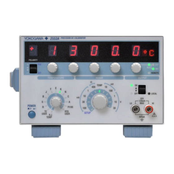
Model 2553A
Precision DC Calibrator
Simple Adjustment Procedure
AVERTISSEMENT
Keysight Technologies 3458A or equivalent
Yokogawa Test & Measurement Corporation 2792A05 or equivalent
Coper Electronics ZC-114A or equivalent
IEC 60584-1 Ed 3.0 or JIS C1602: 1995 compliant
2nd Edition : October 2017 (YMI)
All Rights Reserved, Copyright © 2014, Yokogawa Test & Measurement Corporation
Printed in Japan
WARNING
IM 2553A-71EN 1/8
2nd Edition
Advertisement

Related Manuals for YOKOGAWA 2553A


Summary of Contents for YOKOGAWA 2553A
- Page 1 The simple adjustment values are retained even when the settings are initialized. If you need to adjust the 2553A more accurately than that is possible with the simple adjustment feature or if you want calibration and adjustment to be performed at a YOKOGAWA factory, contact your nearest YOKOGAWA dealer.
- Page 2 Turn the three output setting dials on the right to set the password “111”. Flip the POLARITY switch down. POLARITY switch Three output setting dials on the right 5. When authentication is successful, the 4. Set the password “111”. 2553A switches to simple adjustment mode. IM 2553A-71EN...
- Page 3 Flip the OUTPUT switch up. The 2553A output turns on. The output value that corresponds to the adjustment range and adjustment point is transmitted from the 2553A output terminals to the measuring instrument (DMM). While viewing the measured value, turn the three output setting dials on the left to adjust the 2553A output value. For details on the adjustable range of each adjustment range, see the later explanation.
- Page 4 Adjustment 2553A Adjustment Range Output at Each Adjustment Point Adjustable Range Range ±0 ±1000 ppm of the adjustment range 1 mA +1 mA -1 mA 0 mA 1 mA (equivalent to ±0.001 mA) ±1000 ppm of the adjustment range 10 mA +10 mA -10 mA 0 mA 10 mA (equivalent to ±0.01 mA) Depending on the DMM current range, you may not be able to attain sufficient accuracy. If necessary, use a standard resistor and adjust by using a DMM voltage range, as shown in the next section. Use either method depending on the accuracies of the available ranges on the DMM. IM 2553A-71EN...
- Page 5 0 mA (equivalent to ±0.03 mA: (DMM measurement/R ±1000 ppm of the adjustment range 100 mA +100 mA -100 mA 0 mA (equivalent to ±0.1 mA: (DMM measurement/R : 2792A05 resistance (calibration value) Thermocouple Wiring Example 2553A FUNCTION: DCV Adjustment 2553A Adjustment Range Thermoelectromotive Force at Adjustable Range Range Each Adjustment Point ±0 Thermocouple (TEMP) 50 mV 0 mV ±99.9 (equivalent to ±99.9 µV) 100 mV IM 2553A-71EN...
- Page 6 Adjust to 0°C equivalent. FUNCTION: DCV RANGE: 100 mV Standard temperature device ZC-114A Adjustment • The internal RJC is affected by the adjustment results of the thermocouple adjustment range, mentioned earlier. Adjust the internal RJC after you have adjusted the thermocouple adjustment range. • Adjust to a value equivalent to 0°C by taking into account the error in the thermocouple that you will be using. • The 2553A output display is in unit of °C, but the output terminals produce the thermoelectromotive force corresponding to the specified temperature. • For details on handling the standard temperature device, follow the instruction manual of the device. 2553A Adjustment Range Output at Each Adjustment Point Adjustable Range Range Internal RJC (SETUP) 0°C ±2.00°C...
- Page 7 (resolution: 0.01°C) Example :CALIBRATE:RANGE 1V Example :CALIBRATE:ADJUST:VALUE 1000 :CALIBRATE:RANGE? :CALIBRATE:ADJUST:VALUE? -> 1000 -> :CALIBRATE:RANGE 1.0E+00 Explanation The adjustable range and resolution vary Explanation • Before setting <Voltage>, use the depending on the :CALibrate:FUNCtion command :CALibrate:FUNCtion command to set the function to VOLTage. setting. If a value outside the adjustable range Before setting <Current>, use the is specified, a “222:Dataout of range” error will :CALibrate:FUNCtion command to set the occur. function to CURRent. Before setting <Resistance>, use the :CALibrate:FUNCtion command to set the function to RESistance. If you set range of a different function, a “131: Invalid suffix” error will occur. IM 2553A-71EN...
- Page 8 :CALibrate:WRITe command before changing the adjustment range. :CALibrate:STATe Function Sets or queries the output on/off state for simple adjustment. Syntax :CALibrate:STATe <Boolean> :CALibrate:STATe? ON|1: Enabled OFF|0: Disabled Example :CALIBRATE:STATE ON :CALIBRATE:STATE? -> :CALIBRATE:STATE 1 Explanation If the :CALibrate:ADJust:POINt command is set to OFF, this command (:CALibrate:STATe) cannot be set to ON. :CALibrate:WRITe Function Writes the simple adjustment values to the 2553A internal memory. Syntax :CALibrate:WRITe Example :CALIBRATE:WRITE IM 2553A-71EN...
Need help?
Do you have a question about the 2553A and is the answer not in the manual?
Questions and answers