YOKOGAWA AQ1210A Getting Started Manual
Otdr multi field tester
Hide thumbs
Also See for AQ1210A:
- User manual (282 pages) ,
- User manual (290 pages) ,
- User manual (73 pages)
Table of Contents
Advertisement
Quick Links
Download this manual
See also:
User Manual
Advertisement
Table of Contents

Related Manuals for YOKOGAWA AQ1210A


Summary of Contents for YOKOGAWA AQ1210A
- Page 1 User’s AQ1210A, AQ1215A, AQ1210E, Manual AQ1215E, AQ1215F, AQ1216F OTDR Multi Field Tester Getting Started Guide IM AQ1210-02EN 1st Edition...
- Page 2 Thank you for purchasing the AQ1210A, AQ1215A, AQ1215E, AQ1215F, AQ1216F OTDR (Optical Time Domain Reflectometer) Multi Field Tester. This Getting Started Guide focuses on the handling precautions, basic operations, and specifications of this instrument. To ensure correct use, please read this manual thoroughly before operation. Keep this manual in a safe place for quick reference.
-
Page 3: Product Registration
• Every effort has been made in the preparation of this manual to ensure the accuracy of its contents. However, should you have any questions or find any errors, please contact your nearest YOKOGAWA dealer. • Copying or reproducing all or any part of the contents of this manual without the permission of YOKOGAWA is strictly prohibited. Trademarks •... -
Page 4: Checking The Contents Of The Package
Unpack the box, and check the contents before operating the instrument. If the wrong items have been delivered, if items are missing, or if there is a problem with the appearance of the items, contact your nearest YOKOGAWA dealer. AQ1210A, AQ1215A, AQ1210E, AQ1215E, AQ1215F, AQ1216F Check that the product that you have received is the same product that you ordered. - Page 5 (Battery pack) * IM AQ1210-01EN and IM AQ1210-17EN are contained in a PDF file in this IMAQ1210-92Z1 instrument internal memory. A printed manual can also be purchased separately. IM739884-01Z1 Contact your nearest YOKOGAWA dealer to purchase a copy. IM AQ1210-02EN...
- Page 6 Optional Accessories The following optional accessories are available for purchase separately. For information about ordering accessories, contact your nearest YOKOGAWA dealer. Item Model/Part No. Note Soft carrying case SU2006A — Shoulder strap B8070CY — USB Cable (TypeC to TypeC) A1681WL —...
-
Page 7: Conventions Used In This Guide
Conventions Used in This Guide Notes The notes and cautions in this guide are categorized using the following symbols. Improper handling or use can lead to injury to the user or damage to the instrument. This symbol appears on the instrument to indicate that the user must refer to the user’s manual for special instructions. -
Page 8: Safety Precautions
Keep this manual until you dispose of the instrument. YOKOGAWA assumes no liability for the customer’s failure to comply with these requirements. The following symbols are used on this instrument. - Page 9 • Use only the supplied USB cable to charge the instrument. • With the instrument turned off, when the battery pack is charged using the USB-AC adapter that YOKOGAWA recommends , if the battery pack is still charging after 8 hours, stop charging it immediately.
- Page 10 Only use the USB memory device or USB dongle that YOKOGAWA recommends. YOKOGAWA provides no guarantee if you use the device that YOKOGAWA do not recommend. This instrument may be powered off without alarm forcibly if you use the device that YOKOGAWA do not recommend.
- Page 11 • Avec l'instrument hors tension, lorsque le pack de batteries est chargé à l'aide de l'adaptateur USB-CA recommandé par YOKOGAWA, si le pack de batteries est encore en charge après 8 heures, arrêter le chargement immédiatement. • Ne pas charger l'instrument en plein soleil (par exemple sur le tableau de bord de la voiture ou sur le rebord d'une fenêtre), dans un véhicule stationné...
- Page 12 Ne pas retirer le capot, ni démonter ou modifier l’instrument Seul le personnel YOKOGAWA qualifié est habilité à retirer le capot et à démonter ou modifier l’instrument. Certains composants à l’intérieur de l’instrument sont à haute tension et par conséquent, représentent un danger.
- Page 13 Safety Precautions for Laser Products This instrument uses a laser light source. This instrument is a Class 1M laser product and Class 3R laser product as defined by IEC60825-1:2007 Safety of Laser Products-Part 1: Equipment classification and requirements. In addition, this instrument complies with 21 CFR 1040.10 and 1040.11 except for deviations pursuant to Laser Notice No.
- Page 14 Maximum Output Power Mode Field Beam Divergence Wavelength Diameter Angle AQ1210A OTDR port (PORT1) 1M or 1 1310 nm/1550 nm CW: 50 mW, 9 μm 11.5° Pulse: 200 mW, Pulse width: 20 μs, Duty: ≤ 3.0% VLS port 650 nm CW: 5 mW 9 μm...
-
Page 15: Regulations And Sales In Each Country Or Region
With reference to the equipment types in the WEEE directive, this product is classified as a “Monitoring and control instruments ” product. When disposing of products in the EU, contact your local Yokogawa Europe B.V. office. Do not dispose in domestic household waste. - Page 16 Authorized Representative in the EEA Yokogawa Europe B.V. is the authorized representative of Yokogawa Meters & Instruments Corporation for this product in the EEA. To contact Yokogawa Europe B.V., see the separate list of worldwide contacts, PIM 113-01Z2.
-
Page 17: How To View The User's Manual
The following PDF file is stored in the USERS_MANUAL folder in this instruments internal memory. File Name Manual Title Manual No. Features & Operation Manual_*.pdf AQ1210A, AQ1215A, AQ1210E, AQ1215E, AQ1215F, IM AQ1210-01EN “*“ is used to indicate the revision number. AQ1216F OTDR Multi Feild Tester User’s Manual Communication Interface_*.pdf... -
Page 18: Table Of Contents
Contents Setting the Language and Date and Time Product Registration ..............2 .....41 Checking the Contents of the Package ........3 Selecting the Language to Display........41 Conventions Used in This Guide ..........6 Selecting the Date and Time to Display ........42 Safety Precautions ..............7 Setup ..................43 Regulations and Sales in Each Country or Region ....14... - Page 19 Background Information on Measurements ..58 How to View Optical Pulse Measurement Waveforms (TRACE screen) ..................58 How to View the Icon Display (MAP Screen) ......59 Terminology ................60 Analysis using the Emulation Software ....61 Maintenance and Inspection ........62 Replacing the Optical Adapter ..........62 Removing the Battery Pack ...........64 Recommended Part Replacement ........66 Disposing of the Instrument ..........66...
-
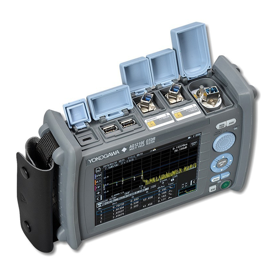
Page 20: Component Names And Functions
Component Names and Functions Front Panel REAL TIME key Press to start or stop the real-time measurement of optical pulses. Used to perform touch panel operations. AVG Key Press to start or stop the averaged measurement of optical pulses. LASER LED Illuminates in red when the light is being emitted from the light source port. -
Page 21: Top Panel
Component Names and Functions Top Panel without /VLS option Rear panel Type A USB port Used to connect a USB memory device or USB dongle. Type C USB port VLS port (/VLS option) Used to charge the instrument with the USB-AC Used for VLS output. -
Page 22: Rear And Side Panels
Component Names and Functions Rear and Side Panels Protector Battery cover Stand Strap slot Pull the stand out to use the instrument in a tilted position. IM AQ1210-02EN... -
Page 23: Making Preparations For Measurements
Unplug If Abnormal Behavior Occurs If you notice smoke or unusual odors coming from the instrument, immediately turn off the power, unplug the USB-AC adapter, remove the battery pack and contact your nearest YOKOGAWA dealer. Handle the USB-AC Adapter and USB Cable Properly Do not place objects on top of the USB-AC adapter or USB cable, and keep them away from heat sources. -
Page 24: Attaching The Strap
Making Preparations for Measurements Attaching the Strap Attaching the Hand Strap Pass the hand strap through the loop on the lower-left side of the instrument. Hand strap Pass the hand strap through the hand strap cover. Buckle Pass the hand strap through the loop on the upper-left side of the instrument. -
Page 25: Attaching The Battery Pack
Making Preparations for Measurements Attaching the Battery Pack WARNING • Do not connect or disconnect the battery pack while electricity is being supplied by the AC adapter. • To prevent problems before they occur, periodically inspect the battery pack exterior to confirm that there is no damage such as cracks or deformations and to confirm that there is no fluid leakage. - Page 26 Making Preparations for Measurements Loosen the battery cover screws with a Phillips Connect the battery pack’ s power supply lead wire screwdriver until the screw head moves up and down. plug to the instrument’ s battery connector. Pull the battery cover toward you, lift, and remove. Battery pack Plug The lead wires are...
- Page 27 Making Preparations for Measurements Check that the battery cover is not loose, and then fasten Attach the battery cover from the bottom panel side, the attachment screws with a Phillips screwdriver. making sure that the hooks on the battery cover enter Tightening torque: Approx.
-
Page 28: Connecting The Usb-Ac Adapter And Charging The Instrument
Connecting the USB-AC Adapter and Charging the Instrument WARNING • Only use the USB-AC adapter that YOKOGAWA recommends. • Use the USB-AC adapter after confirming that the rated supply voltage matches the voltage of the power supply. • Use only the supplied USB cable. - Page 29 • If the instrument’s connector cover comes off, bend the cover axle and reattach it. • For details on the USB-AC adapter, contact your nearest YOKOGAWA dealer. • The battery cannot be charged by connecting to a PC (YOKOGAWA provides no guarantee). Be sure to connect the USB-AC adapter to charge the battery.
- Page 30 15 hours, but charging will be suspended after about 15 hours by the protection circuit. If battery charging does not complete within 8 hours with the power turned off, stop immediately. The battery in the instrument may be malfunctioning. Contact your nearest YOKOGAWA dealer. • Power supply icon Power supply icon blinks if the USB-AC adapter has insufficient power supply ability.
- Page 31 Making Preparations for Measurements Note Over Discharge and Long Periods of Storage • If you do not use the instrument for an extended period of time with the battery pack connected to it, the battery pack may become over discharged. This shortens the service life of the battery pack. To avoid over discharging, if you will not use the instrument for one week or longer, charge the battery pack, remove it from the instrument, and store the battery pack away from direct sunlight in a location that has an ambient temperature of 10°C to 30°C.
-
Page 32: Connecting Optical Fiber Cables
Making Preparations for Measurements Connecting Optical Fiber Cables WARNING • When the instrument generates light, light is emitted from the light source ports. Do not disconnect the connected optical fiber cables. Visual impairment may occur if the light enters the eye. •... - Page 33 Making Preparations for Measurements French AVERTISSEMENT • Lorsque cet instrument génère de la lumière, la lumière est émise à travers les ports de source lumineuse. Ne pas débrancher les câbles de fibre optique connectés. Des lésions oculaires peuvent être causées si le faisceau lumineux pénètre l’oeil.
- Page 34 Making Preparations for Measurements Clean the connector end face of the optical fiber cable before connecting it to the instrument. If dust is adhered to the connector end face, it may damage the instrument’s optical port. If this happens, the instrument will not be able to make correct measurements. Firmly press the connector end face of the optical Open the optical port cover on the instruments top panel.
-
Page 35: Turning The Power On
• Is the USB-AC adapter connected correctly? See page 27. • Are you holding down the power switch for at least 2 seconds? If the instrument still does not work properly after checking these items, contact your nearest YOKOGAWA dealer for repairs. Warm Up To enable more accurate measurements, allow the instrument to warm up for at least 5 minutes after it is turned on. -
Page 36: Screen Operations
Screen Operations MENU Screen When you turn on the instrument or press MENU, the menu screen appears. You can change the screen that appears when you start the instrument to the OTDR screen. For the setup procedure, see section 10.6 in the User’s Manual, IMAQ1210-01EN. The references are chapters and sections in the User’s Manual, IMAQ1210-01EN. -
Page 37: Otdr Measurement Screen
Screen Operations OTDR Measurement Screen TRACE Screen Tap OTDR on the MENU screen. The OTDR measurement results are displayed as waveforms on the data display screen. The references are chapters and sections in the User’s Manual, IMAQ1210-01EN. Switches to the MAP screen. Laser on indication Auto save indicator (see sec. - Page 38 Screen Operations MAP Screen Tap OTDR on the MENU screen. The OTDR measurement results are displayed as icons on the data display screen. The references are chapters and sections in the User’ s Manual, IMAQ1210-01EN. Auto save indicator (see sec. 2.1) Laser on indication Power supply icon display Averaged measurement in progress indication...
-
Page 39: Using The Rotary Knob And Arrow Keys
Screen Operations Using the Rotary Knob and Arrow Keys This section explains how to use the rotary knob and arrow keys using the ANALYSIS screen (partial extraction) of the SETUP item as an example. Move the cursor to the item that The following setup operation patterns are available depending on the display you want to set using the arrow button shape. -
Page 40: Using The Touch Panel
Screen Operations Using the Touch Panel The basic touch panel operations are described below. Tap refers to the act of gently hitting the screen with your finger. Tapping is used on the instrument screen to select areas with a mark, close a setup menu, and so on. -
Page 41: Entering Text
Screen Operations Entering Text When you select a setting, a character input dialog box appears if necessary. This section explains the operation after a character input dialog box is displayed. Entering Alphanumeric Characters Deletes the character before the cursor position Cursor Moves the cursor to the right Moves the cursor to the left... -
Page 42: Setting The Language And Date And Time
Setting the Language and Date and Time Selecting the Language to Display Press MENU to display the MENU screen. Press SETUP to display the System Setup screen. Tap the Language button to display the language setup menu. System Setup Screen Language setup menu The languages that... -
Page 43: Selecting The Date And Time To Display
Setting the Language and Date and Time Selecting the Date and Time to Display Press MENU to display the MENU screen. Press SETUP to display the System Setup screen. Tap the Date & Time Set button to display the following screen. System Setup Screen Set the year, month, and day. -
Page 44: Setup
Setup Setting Measurement Conditions (Measure) 2.1, “Measurement (Measure) Conditions” in the User’s Manual Tap OTDR on the MENU screen. Press SETUP to display the setup screen. Tap the MEASURE tab to display the following screen. Set wavelength 1. MEASURE tab Set wavelength 2. -
Page 45: Setting The Analysis Conditions (Analysis)
Setup Setting the Analysis Conditions (Analysis) 2.2, “Analysis (Analysis) Conditions” in the User’s Manual Tap OTDR on the MENU screen. Press SETUP to display the setup screen. Tap the ANALYSIS tab to display the following screen. Splice loss threshold ANALYSIS tab (0.01dB to 9.99dB) Return loss threshold (20dB to An event is detected... -
Page 46: Setting Display Conditions (Otdr)
Setup Setting Display Conditions (OTDR) 2.3, “Display (OTDR) Conditions” in the User’s Manual Tap OTDR on the MENU screen. Press SETUP to display the setup screen. Tap the OTDR tab to display the following screen. Set the marker type (Marker, Line). OTDR tab Turns approximated line Marker:... -
Page 47: Waveform Measurement
Waveform Measurement Performing Real-time Measurement 3.1, “Performing Real-time Measurement” in the User’s Manual In real-time measurement, the waveform display is updated in real time. This feature is used to monitor the waveforms. Tap OTDR on the MENU screen. Tap Wavelength to select the wavelength to be measured. Press REALTIME to start a measurement. -
Page 48: Performing High-Precision Waveform Monitoring In Real-Time
Waveform Measurement Performing High-Precision Waveform Monitoring in Real-time 3.1, “Performing Real-time Measurement” in the User’s Manual The real-time measurement waveform display updates the displayed waveform each time an optical fiber cable is measured. This update rate can be changed according to your application. Before configuring this feature, start real-time measurement according to the steps on the previous page. -
Page 49: Performing Averaged Measurements
Waveform Measurement Performing Averaged Measurements 4.1, “Performing Averaged Measurements in TRACE Mode” in the User’s Manual In averaged measurements, the data that is acquired from each pulse is averaged and displayed. Tap OTDR on the MENU screen. Tap Wavelength to select the wavelength to be measured. Press AVG to start a measurement. -
Page 50: Analyzing Waveforms And Events
Analyzing Waveforms and Events Measuring the Distance and Loss between Two Points 1.4, “Analyzing Measured Data” in the User’s Manual You can place two markers on the waveform on the data display screen and measure the distance and loss between the markers. Tap OTDR on the MENU screen. -
Page 51: Measuring The Return Loss
Analyzing Waveforms and Events Measuring the Return Loss 1.4, “Analyzing Measured Data” in the User’s Manual You can place two markers on the waveform on the data display screen and measure the return loss between the markers. Tap OTDR on the MENU screen. Tap the Marker soft key and then the 2 Point Markers soft key. -
Page 52: Measuring The Splice Loss
Analyzing Waveforms and Events Measuring the Splice Loss 1.4, “Analyzing Measured Data” in the User’s Manual You can place four markers on the waveform on the data display screen and measure the splice loss between the markers. Tap OTDR on the MENU screen. Tap the Marker soft key and then the 4 Point Markers soft key. -
Page 53: Zooming In On Or Out Of Waveforms
Analyzing Waveforms and Events Zooming In on or Out of Waveforms 6.2, “Zooming Waveforms” in the User’s Manual You can zoom the waveform at the specified position on the data display screen. Tap OTDR on the MENU screen. Display a waveform on the screen. Tap the screen near the location where you want to display a cursor. -
Page 54: Analyzing Events
Analyzing Waveforms and Events Analyzing Events TRACE Screen 5.1, “Analyzing in TRACE Mode” in the User’s Manual The numbers of detected events are displayed on the measured waveform. Tap OTDR on the MENU screen. Display a waveform on the screen. Tap the Event Analysis soft key to execute an event analysis. - Page 55 Analyzing Waveforms and Events MAP Screen 5.2, “Analyzing in MAP Mode” in the User’s Manual The event analyzed in TRACE mode on the previous page is displayed as an icon on the MAP screen. Tap MAP to change to the MAP screen. When the MAP screen is displayed, the MAP button changes to a TRACE button. If you execute an averaged measurement after displaying the MAP screen, the event is displayed as an icon automatically when the measurement is completed.
-
Page 56: Creating Reports
Creating Reports Exporting the Waveforms on the Screen to Report Files 9.5, “Creating Report Files” in the User’s Manual Tap OTDR on the MENU screen. Display a waveform on the screen. Tap the FILE icon and then REPORT to display the file list screen. File list screen File name Exports a report file... -
Page 57: Exporting File List Data To Report Files
Creating Reports Exporting File List Data to Report Files 9.5, “Creating Report Files” in the User’s Manual Tap OTDR on the MENU screen. Tap the FILE icon and then FILE to display the file list screen. Select the waveform data file to export to a report file. For the procedure to select multiple files, see section 9.6 in the User’s Manual IM AQ1210-02EN. - Page 58 Creating Reports Tap the export report icon. A report file will be created in the same folder as selected file. Report file Label information Event Icon Display Measurement conditions Export report icon Waveform display Event search conditions Event analysis results IM AQ1210-02EN...
-
Page 59: Background Information On Measurements
Background Information on Measurements How to View Optical Pulse Measurement Waveforms (TRACE screen) The optical pulse applied to an optical fiber cable is reflected at different points of the optical fiber such as its connections, bent sections, and the open end of the fiber. These sections generate loss. The measured result is displayed as a waveform that has distance represented in the horizontal direction and loss level represented in the vertical direction. -
Page 60: How To View The Icon Display (Map Screen)
Background Information on Measurements How to View the Icon Display (MAP Screen) Losses and reflections that occur at connections, bent sections, and open ends are displayed using icons. Events in the section from the measurement start point to the open end are displayed in order from the start point. Connector Bend Incident ray... -
Page 61: Terminology
Background Information on Measurements Terminology Near-end reflection Reflection occurs at the gap in the connector connecting the instrument and optical fiber cable. In the section where this reflection is detected, loss and reflections that occur at connections cannot be detected. This section is called a dead zone. Backscatter When light travels through an optical fiber cable, Rayleigh scattering occurs due to inconsistencies in the density and composition of materials that are smaller than the unit of wavelength. -
Page 62: Analysis Using The Emulation Software
Analysis using the Emulation Software Waveform data measured with the instrument can be analyzed on a PC by using the AQ7933 OTDR Emulation Software. This software also has a PDF report creation feature, which is convenient for creating construction reports. Create a PDF construction report Waveform data saved in SOR format using the instrument can be displayed on using the report creation feature of the... -
Page 63: Maintenance And Inspection
Maintenance and Inspection Replacing the Optical Adapter WARNING When replacing the optical adapter, turn off the instrument to prevent the light from accidentally being emitted from the light source port. Replacing the optical adapter with the instrument turned on may cause the emitted light to accidentally enter the eye. - Page 64 Maintenance and Inspection Removal Check that the instrument is turned off. Open the OTDR ports or the OPM port (/SPM, /HPM or /PPM option) cover. Remove the optical adapter attachment screws (nominal diameter: M2, length: 4 mm) with a Phillips screwdriver. If the OPM port (when /SPM or /HPM option) turn the knob to the left to loosen.
-
Page 65: Removing The Battery Pack
Maintenance and Inspection Removing the Battery Pack WARNING • Do not connect or disconnect the battery pack while electricity is being supplied by the USB-AC adapter. • To prevent problems before they occur, periodically inspect the battery pack exterior to confirm that there is no damage such as cracks or deformations and to confirm that there is no fluid leakage. - Page 66 Maintenance and Inspection Loosen the battery cover screws with a Phillips Insert your finger into the hole so that the battery pack can be screwdriver until the screw head moves up and down. removed. Pull the battery cover toward you, lift, and remove. Screws Battery cover Hole...
-
Page 67: Recommended Part Replacement
Maintenance and Inspection Recommended Part Replacement The following parts are wearable. It is recommended to replace them after the time period indicated below. For replacement of parts, please contact your nearest Yokogawa representative. Parts with Limited Service Life Part Name... -
Page 68: Specifications
SM (ITU-T G.652) 3 ns pulse width (when AQ1215A and AQ1215E), 5 ns pulse width (when AQ1210A and AQ1210E), 55 dB or more return loss, at a point at 1.5 dB or less from the peak value under unsaturated conditions 10 ns pulse width, 55 dB or more return loss, point where the backscattering light level is attenuated to a value within the regular value ±... -
Page 69: Power Checker (/Pc Option)
Specifications AQ1215F, AQ1216F Specifications Item AQ1215F AQ1216F Center wavelength 1310 nm ± 25 nm 1310 nm ± 25 nm 1550 nm ± 25 nm 1550 nm ± 25 nm 1650 nm ± 5 nm 1650 nm ± 25 nm Event dead zone 0.7 m (1310 nm) 0.7 m (1310 nm) 0.7 m (1550 nm) -
Page 70: Optical Power Meter (Option)
Specifications Ambient temperature: 23°C±2°C, CW light, wavelength: 1310 nm, light source spectral width: 10 nm or less, power level: 100 μW (–10 dBm), optical fiber: SM (ITU-T G.652), changes to the measuring instrument due to the passage of time are not included. Optical Power Meter (Option) Specification Item... -
Page 71: Visible Light Source (/Vls Option)
Specifications Visible Light Source (/VLS option) Item Specification Wavelength 650 nm ± 20 nm Optical output level –3 dBm or more (Peak) Modulation mode CW, CHOP (2 Hz) Optical output port VLS port The ambient temperature is 23°C ± 2°C unless otherwise stated. Functions Item Specification... -
Page 72: General Specifications
Specifications General Specifications Item Specifications Operating Ambient temperature –10°C to 50°C, (10°C to 35°C during battery charge environment Ambient humidity 5 to 90%RH (no condensation) Altitude 4000 m or less Storage Ambient temperature –20°C to 60°C environment Ambient humidity 0 to 90%RH (no condensation) Power supply Rated supply voltage 5 VDC ±... -
Page 73: External Dimensions
Specifications External Dimensions Unit : mm (approx. inch) If not specified, the tolerance is ± 3%. However, in cases of less than 10 mm, the tolerance is ± 0.3 mm. ( 0.15 ) ( 8.27 ) ( 0.15 ) ( 2.72 ) IM AQ1210-02EN...
Need help?
Do you have a question about the AQ1210A and is the answer not in the manual?
Questions and answers