Table of Contents
Advertisement
Quick Links
Advertisement
Table of Contents

Related Manuals for YOKOGAWA DL9000 Series


Summary of Contents for YOKOGAWA DL9000 Series
- Page 1 DL9040/DL9140/DL9240 Series Digital Oscilloscope IM 701310-01E 8th Edition...
- Page 2 Product Registration Thank you for purchasing YOKOGAWA products. YOKOGAWA provides registered users with a variety of information and services. Please allow us to serve you best by completing the product registration form accessible from our homepage. http://tmi.yokogawa.com/ PIM 103-03E...
- Page 3 • For purposes of this manual, the TM and ® symbols do not accompany their respective trademark names or registered trademark names. • Other company and product names are trademarks or registered trademarks of their respective companies. 8th Edition : April 2009 (YK) All Rights Reserved, Copyright © 2005 Yokogawa Electric Corporation IM 701310-01E...
- Page 4 Revisions • 1st Edition: June 2005 • 2nd Editon: August 2005 • 3rd Editon: January 2006 • 4th Editon: June 2006 • 5th Editon: Decenber 2006 • 6th Editon: August 2007 • 7th Edition: Edition: June 2008 June 2008 • 8th Edition: April 2009 IM 701310-01E...
-
Page 5: Checking The Contents Of The Package
MODEL WARNING Œx?? MODEL SUFFIX SUFFIX CAUTION ’ˆÓ Made in Japan YOKOGAWA VIDEO OUT 100 - 120/220 - 240 V AC (XGA) PROBE POWER( 12 V DC 300 VA MAX 50/60 Hz Made in Japan TRIG COMP OUT TRIG IN... - Page 6 Communication interface User’s manual B8080RE(CD) *1 When using the optional built-in printer (/B5) *2 Included with the /F5, /F7, or /F8 option or /G4 option. *3 Printed manual IM701310-17E can be purchased separately. Contact your nearest YOKOGAWA dealer. IM 701310-01E...
- Page 7 Checking the Contents of the Package Optional Accessories (Sold Separately) The optional accessories below are available for purchase separately. For information and ordering, contact your nearest YOKOGAWA dealer. Name Model Remarks With the YOKOGAWA probe interface Active probe PBA2500 701913 1913 DC to 2.5 GHz bandwidth, 100 k...
-
Page 8: Safety Precautions
The general safety precautions described herein must be observed during all phases of operation. If the instrument is used in a manner not specified in this manual, the protection provided by the instrument may be impaired. Yokogawa Electric Corporation assumes no liability for the customer’s failure to comply with these requirements. - Page 9 To prevent the possibility of electric shock or fire, be sure to use the power cord supplied by YOKOGAWA. The main power plug must be plugged into an outlet with a protective earth terminal. Do not invalidate this protection by using an extension cord without protective earth grounding.
-
Page 10: Waste Electrical And Electronic Equipment
With reference to the equipment types in the WEEE directive Annex 1, this product is classified as a “Monitoring and Control instrumentation” product. Do not dispose in domestic household waste. When disposing products in the EU, contact your local Yokogawa Europe B. V. office. viii IM 701310-01E... -
Page 11: Symbols And Notation Used In This Manual
Symbols and Notation Used in This Manual Safety Markings The following markings are used in this manual. Improper handling or use can lead to injury to the user or damage to the instrument. This symbol appears on the instrument to indicate that the user must refer to the user’s manual for special instructions. -
Page 12: Workflow
Workflow The figure below is provided to familiarize the first-time user with the general workflow of the DL9000. For a description of each item, see the relevant chapter or section. Measurement Preparation Install the DL9000 Section 3.2 Connect the power supply Section 3.3 and turn it ON/OFF Sections 3.4 and 3.5... -
Page 13: Table Of Contents
Contents Checking the Contents of the Package.................... iii Safety Precautions ........................... vi Waste Electrical and Electronic Equipment ................... viii Symbols and Notation Used in This Manual ..................ix Workflow ............................x Chapter 1 Names and Functions of Parts Top Panel, Front Panel, and Rear Panel ................1-1 Operating Keys and Knobs .................... - Page 14 Contents Setting Time Axis (T/div) ....................5-10 Using the Auto Scale Function ..................5-11 5.10 Canceling the Offset Value ..................... 5-12 5.11 Displaying the Waveform Inverted .................. 5-13 5.12 Turning the Display of the Scale Value ON/OFF ............5-14 5.13 Correcting the Skew ....................... 5-15 5.14 Automatic Zero Adjustment of the Current Probe ............
- Page 15 Contents Changing the Graticule ..................... 8-9 Adjusting the Backlight ....................8-10 Setting Signal Labels .......................8-11 Taking and Clearing Snapshots ..................8-12 Setting the Translucent Display, Waveform Display Colors, and Brightness ....8-13 Chapter 9 Computation Setting Computation Channels, Operators, Units, and Display Ranges ......9-1 Performing Linear Scaling ....................
- Page 16 Contents Chapter 13 Saving and Loading Measurement Data 13.1 Flash ATA Memory Card ....................13-1 13.2 Connecting a USB Storage Medium to the USB Port ............ 13-2 13.3 Connecting to a Network Drive ..................13-3 13.4 Saving/Loading the Setup Data ..................13-4 13.5 Saving/Loading the Measurement Data ...............
- Page 17 Contents Chapter 18 Troubleshooting, Maintenance, and Inspection 18.1 If a Problem Occurs ......................18-1 18.2 Messages and Corrective Actions .................. 18-2 18.3 Carrying Out a Self-Test ....................18-7 18.4 System Overview ......................18-10 18.5 Collectively Deleting the Data in the Internal Memory and Built-in Hard Disk ....18-11 18.6 Formatting Internal Memory and Built-in Hard Disk .............
-
Page 18: Chapter 1 Names And Functions Of Parts
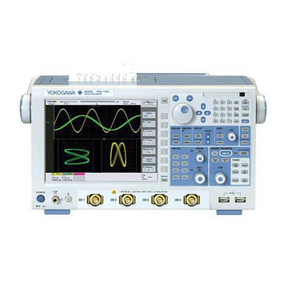
Chapter 1 Names and Functions of Parts Top Panel, Front Panel, and Rear Panel Top Panel Built-in printer Prints the display contents. For installing the paper roll, see section 12.1. For printing operations, see section 12.2. Front Panel Soft keys Used to select items on the soft key menu that appears on the screen during setup. - Page 19 External trigger Probe power terminal (option) input terminal Used to supply power to an FET probe or Used when inputting an a current probe made by YOKOGAWA. external trigger signal. See section 3.4. See section 16.1. Video signal output connector Used when displaying the DL9000 display image on an external display.
- Page 20 Operating Keys and Knobs Vertical Axis, Channel, and Computation CH1 to CH4 keys ►Sections 5.1 to 5.14, 8.6 These display menus for switching the display of input channel ON/OFF, vertical position, coupling, probe type, offset voltage, bandwidth limit, expansion or reduction of the vertical axis, linear scaling, and signal labels.
- Page 21 1.2 Operating Keys and Knobs LEVEL/COUPLING key ►Section 6.5 Displays a menu for trigger coupling, HF rejection, Window comparator, and other settings. T/DIV knob ►Section 5.8 Sets the time axis scale. If you change this while signal acquisition is stopped, the change takes effect when signal acquisition is restarted.
- Page 22 1.2 Operating Keys and Knobs Screen Image Printing/Data Saving/History Waveform/etc. RESET key Returns a numeric input value to its default. SET key Confirms a menu item selected with the rotary knob. Arrow keys ( keys) The left and right arrow keys move the digit cursor sideways when entering a numeric value.
-
Page 23: Screen Display
Screen Display Normal Waveform Display Screen Signal acquisition status Pre (acquiring pre data) Stopped Running (acquisition in progress) Post (acquiring post data) Waiting for trigger Sample rate Acquisition mode Trigger position T/div. See section 4.2 Signal Displayed record acquisition count length Trigger mode Trigger source, Polarity... - Page 24 1.3 Screen Display Screen Displaying Zoom Waveforms T/div of Z1 Zoom position of the zoom waveform Z1 X-axis of Z1 Zoom position of the zoom waveform Z2 zoom range T/div of the normal waveform Displayed record Y-axis of Z1 length of the Normal zoom range waveform Normal waveform...
-
Page 25: Chapter 2 Explanation Of Functions
Chapter 2 Explanation of Functions Block Diagram System Configuration Input USB peripheral Built-in printer (optional) device interface Screen image print USB mouse Waveform data Setup data External USB Input Screen image data device DL9240L 10GS/s 1.5GHz USB keyboard DIGITAL OSCILLOSCOPE RESET MENU PRINT... -
Page 26: Channels And Displayed Waveforms
Channels and Displayed Waveforms There are three types of waveform that can be displayed on the DL9000. • Input waveforms • Computed waveforms • Reference waveforms The reference waveform can be selected from input waveforms, computed waveforms, and previously stored input or computed waveforms. The DL9000 provides the following channels. -
Page 27: Vertical And Horizontal Axes
Vertical and Horizontal Axes The vertical sensitivity setting is used to adjust the displayed amplitude of the waveform for easy viewing of the signal. The vertical sensitivity is set by assigning a voltage or a current value to one grid square (1 division) on the screen. By switching attenuators with different attenuation and changing the amplification of the pre-amplifier, the sensitivity changes in steps (for example, voltage sensitivity changes in steps as in 1 V/div, 2 V/div, and 5 V/div). - Page 28 2.3 Vertical and Horizontal Axes Input Coupling ►For the procedure, see section 5.4 If you want to observe just the amplitude of an AC signal, it is best to remove the DC component from the input signal. On the other hand, there are times when you want to check the ground level or observe the entire input signal (both the DC and AC components).
- Page 29 2.3 Vertical and Horizontal Axes Offset Voltage ►For the procedure, see section 5.2 To observe a signal riding on top of a predetermined voltage, an offset voltage can be applied to subtract the predetermined voltage so that only the changes in the signal can be observed with higher vertical sensitivity.
- Page 30 2.3 Vertical and Horizontal Axes Relationship between the Specified Record Length, Time Axis Setting, Sample Rate, and Display Record Length If you change the time axis setting with respect to the specified record length of the acquisition memory, the sample rate and display record length change. For more details about this relationship, see Appendix 1.
- Page 31 Triggers A trigger is a cue used to display the waveform on the screen. A trigger is activated when the specified trigger condition is met. At this point, the waveform is ready to be displayed on the screen. Trigger Source, Trigger Slope, and Trigger Level Trigger source Trigger source refers to the signal that is used in checking the trigger condition.
-
Page 32: Triggers
2.4 Triggers • Edge (Qualified) Activates a trigger on the edge of a single trigger source while the input signal states meet the specified qualification requirements. Qualify: CH1 = H, CH2 = L, AND, Trigger source: CH3, rising L: low level, H: high level Trigger Trigger Qualification false... - Page 33 2.4 Triggers • Edge OR A trigger is activated by an edge on multiple trigger sources. When an Edge OR trigger is used, the frequency of the trigger sources is limited to 200 MHz or less. Width trigger A trigger is activated by the duration of a pulse (pulse width). There are three types of width trigger, as follows.
- Page 34 2.4 Triggers • Pulse State A trigger is activated in any of the following cases. • When the time during which the state condition is met or not met satisfies the relationship with the specified determination time. • The DL9000 checks and normalizes the state condition on the rising or falling edge of the specified signal (clock source).
- Page 35 2.4 Triggers Enhanced • TV trigger This trigger is used when observing a video signal. NTSC (525/60/2), PAL (625/50/2), and HDTV (1125/60/2) standards are supported. The horizontal sync signal can be set to any frequency, allowing a trigger to be taken from any TV signal, not necessarily one of the above standards.
- Page 36 2.4 Triggers Event Interval trigger Taking the trigger condition, excluding Edge OR trigger and TV trigger, as an event, the trigger is activated when the event period, or the interval between two events meets preset time conditions. The time condition is the same as the time condition for the Width trigger.
- Page 37 2.4 Triggers • Event Sequence When the time interval between event 1 occurring and the first occurrence of event 2 meets the specified time condition. If the condition is not met, the DL9000 ignores event 2 that occurred and activates a trigger on event 2 that occurs while the specified time conditions are met.
- Page 38 2.4 Triggers Trigger Position ►For the procedure, see section 6.2 After signal acquisition is started, the DL9000 triggers on the specified trigger condition and displays the waveform of the acquired signal. When the trigger delay described in the next item is set to 0 s, the trigger position coincides with the point at which the trigger condition becomes true.
- Page 39 2.4 Triggers Trigger Hysteresis ►For the procedure, see section 6.5 If there is insufficient trigger level width and noise is present in the trigger source, the trigger point fluctuates each time a trigger is activated. This causes the displayed waveforms to be unstable.
-
Page 40: Acquisition Conditions
Acquisition Conditions Acquisition Mode ►For the procedure, see section 7.1 When storing sampled data in the acquisition memory (see “Signal Flow” in section 2.1), it is possible to perform processing on data and display waveforms based on the processed data. The following three types of data processing are available. Normal Mode In this mode, sampled data is stored in the acquisition memory without special processing. - Page 41 2.5 Acquisition Conditions High Resolution Mode ►For the procedure, see section 7.2 Normally, this unit takes digital values from the 8-bit A/D converter, applies specified processing, and then stores 8-bit values in primary memory. On the other hand, the resolution of the A/D converter can be improved equivalently by placing a bandwidth limit on the input signal.
- Page 42 2.5 Acquisition Conditions Repetitive Sampling Mode In repetitive sampling mode, you can set a time axis that exceeds the maximum sample rate of 5 GS/s (2.5 GS/s if the interleave mode is OFF). In this mode, one waveform is created from several cycles of a repeating signal. This is equivalent to sampling the signal at a higher sample rate than the actual sample rate.
- Page 43 2.5 Acquisition Conditions GO/NO-GO Determination ►For the procedure, see sections 7.9 to 7.16 This is used as a criteria for the action-on-trigger. This function determines whether the acquired signal meets the criteria (GO) or not (NO-GO). The DL9000 can transmit GO/ NO-GO results through the rear panel GO/NO-GO I/O terminal.
- Page 44 2.5 Acquisition Conditions History Search When signal acquisition is stopped, you can search for history waveforms that meet specified conditions. Zone Search ►For the procedure, see sections 11.2 to 11.4 You can search for history waveforms that pass or do not pass a specified search zone. There are three types of search zone, as follows.
- Page 45 Display Waveform Zooming ►For the procedure, see section 8.1 Displayed waveforms can be enlarged in both the time axis and the voltage axis directions. This function is useful when the signal acquisition time is set long and you wish to observe a particular section of the waveform closely. The zoom position can be set in grid div units.
- Page 46 2.6 Display Display Format ►For the procedure, see section 8.2 Splitting the Screen The screen can be split evenly so that input waveforms and computed waveforms can be easily viewed. The screen can be divided in the following ways: Single (no split), Dual (two ways), Triad (three ways), Quad (four ways) Waveform Assignment You can assign channels to the divided windows.
- Page 47 2.6 Display Displaying Signal Labels ►For the procedure, see section 8.6 A label of up to eight characters can be assigned to each signal and displayed. Snapshot and Snap Clear ►For the procedure, see section 8.7 By using the snapshot function, you can temporarily hold the waveform (snapshot waveform) that would be cleared when the screen is updated on the screen.
-
Page 48: Computation
Computation Prescaling and Rescaling ►For the procedure, see sections 9.2 to 9.7 Prescaling linearly scales the source waveform before carrying out computation. The computation uses the scaled values. Rescaling linearly scales the results of the computation. Computed Waveform Display By setting a computation equation for each of CH1 to CH4, and M1 to M4, a maximum of eight computed waveforms can be displayed. - Page 49 2.7 Computation Rotary Count ►For the procedure, see section 9.9 Phase changes between phase A (Source 1) and phase B (Source 2) are counted up or down, taking a rise above a specified level as 1, and a fall below the level as 0. Taking the specified integration start point as 0, the entire region is calculated, counting up toward the newest data, and counting down toward the oldest data.
-
Page 50: Analyzing And Searching
Analyzing and Searching Cursor Measurements ►For the procedure, see section 10.1 Cursors can be placed on the displayed waveform from signal data held in acquisition memory (within the range of the display record length - see Appendix 1), and various measurement values at the intersection of the cursor and waveform can be displayed. - Page 51 2.8 Analyzing and Searching Automated Measurement of Waveform Parameters Automated Measurement of Waveform Parameters ►For the procedure, see section 10.2 Automated measurement can be performed on various measurement parameters of the displayed waveform stored in the acquisition memory. Up to a maximum of 100,000 automatic measurement results can be saved in a file. There are 27 different measurement items.
- Page 52 Count. In the mask test, a mask pattern created with the software supplied free of charge by Yokogawa is read into the DL9000, and the waveforms passing through the mask are counted. In the eye pattern test, the following items are measured in the eye pattern.
- Page 53 2.8 Analyzing and Searching The following formulas are used to calculate each item. V crossing – V base Crossing% = 100 Vtop – Vbase Trising50% – Tfalling50% Duty Cycle Distortion% = 100 T crossing2 – Tcrossing1 EyeHeight = (Vtop - 3 top) –...
- Page 54 2.8 Analyzing and Searching FFT Analysis ►For the procedure, see section 10.7 This executes a Fast Fourier Transform (FFT), and displays the power spectrum. You can select the trace for the real part or the trace for the imaginary part. If the trace for the imaginary part is not set, the real part only is used for calculation, and negative frequencies are not displayed.
- Page 55 2.8 Analyzing and Searching Waveform Parameter Histogram, Trend and List Displays ►For the procedure, see section 10.8 You can display a selected waveform parameter as a histogram or trend. In the histogram display, the average value, standard deviation, peak value, etc of a waveform parameter can be measured.
-
Page 56: Communications
Communications Command-Based Communications (USB/Ethernet) ►For the procedure, refer to the CD Communications Interface User’s Manual A USB interface is provided as standard equipment, and an Ethernet interface is available as an option. Using communication commands, you can output measurement data to a computer for data analysis or control the DL9000 using an external controller to carry out waveform measurements. -
Page 57: Other Useful Functions
2.10 Other Useful Functions Entering Numeric and Text Data from a USB Keyboard ►For the procedure, see section 4.3 A USB keyboard can be connected, and used for entering file names and comments. Since the functions of the keys on the DL9000 front panel are also assigned to keys on the keyboard, the keyboard can be used in the same way as the keys on the DL9000 itself. - Page 58 2.10 Other Useful Functions Saving and Loading Data from a Storage Medium ►For the procedure, see chapter 13 The DL9000 allows various data to be stored to and loaded from the following storage media. • PC card (standard equipment) • External USB device (USB memory/MO disk drive/hard disk drive etc.) •...
- Page 59 Chapter 3 Making Preparations for Measurements Handling Precautions Safety Precautions If you are using this instrument for the first time, make sure to thoroughly read the safety precautions given on pages vi and vii. Do Not Remove the Case Do not remove the case from the instrument. Some sections inside the instrument have high voltages and are extremely dangerous.
- Page 60 3.1 Handling Precautions When Carrying the Instrument Remove the power cord and connecting cables. Hold the handle to carry the DL9000. IN T UT ILI FIL E CL EA SY ST IF T SE T RE SE MA G CL EA ZO OM TO RY HI ST...
-
Page 61: Installing The Instrument
Installing the Instrument Installation Conditions Install the instrument in a place that meets the following conditions. Flat, Even Surface Install the instrument with the correct orientation on a stable, horizontal surface. The recording quality of the printer may be hindered when the instrument is placed in an unstable or inclined place. - Page 62 3.2 Installing the Instrument Ambient Temperature and Humidity Ambient temperature 5 - 40°C Ambient humidity 20 to 80% RH when the printer is not used. (No condensation) 35 to 80% RH when using the printer. (No condensation) Note • To ensure high measurement accuracy, operate the instrument in the 23 �5°C temperature range and 55 �10% RH.
-
Page 63: Connecting The Power
● Check that both the main power switch and power switch of the DL9000 are off before connection the power cord. ● To prevent the possibility of electric shock or fire, be sure to use the power cord for the instrument that was supplied by YOKOGAWA. ● Make sure to perform protective earth grounding to prevent electric shock. Connect the power cord to a three-prong power outlet with a protective earth terminal. ● Do not use an extension cord without a protective earth ground. Otherwise, the protection function will be compromised. - Page 64 3.3 Connecting the Power Turning ON the Power Switch Items to Be Checked before Turning ON the Power • The instrument is properly installed.: “3.2 Installing the Instrument” • The power cord is properly connected.: Previous page Turning ON the Main Power Switch Switch the rear panel power switch to the ON ( | ) position.
- Page 65 3.3 Connecting the Power Power Up Operation A self-test and calibration start automatically when the power switch is turned ON. That lasts approximately 30 seconds. If the check results are satisfactory, the normal waveform display screen will appear. Note • Allow at least 10 seconds before turning ON the power switch after turning it OFF.
-
Page 66: Connecting The Probe
Connecting the Probe Connect a probe (or measurement input cable such as a BNC cable) to the input terminal on the bottom of the front panel. The input impedance is 1 MW ± 1% and approximately 20 pF or 50 W ± 1.5%. WARNING ● Always turn OFF the power of the object to be measured when connecting it to this instrument. - Page 67 Connecting FET Probe, Current Probe, Differential Probe, or Deskew Correction Signal Source If you are using the YOKOGAWA’s FET Probes, Current Probes, Differential Probes, or Deskew Correction Signal Source, use the Probe Power (option) on the DL9000 rear panel for the power supply. For details on the connection procedure, see the manual that comes with the respective product.
- Page 68 Handling Precautions of the Probe Interface Terminals and Probe Power Terminals If you are connecting the YOKOGAWA’s FET Probes, Current Probes, Differential Probes, or Deskew Correction Signal Source to the Probe Power Terminals (Option) on the rear panel, be sure that the total current of the two Probe Power Terminals and the four Probe Interface Terminals does not exceed 1.2 A.
-
Page 69: Compensating The Probe (Phase Correction)
Compensating the Probe (Phase Correction) Be sure to perform phase correction of the probe first when using a probe to make measurements. CAUTION Do not apply external voltage to the signal output terminal for probe compensation adjustment. This may cause damage to the internal circuitry. Procedure Turn ON the power switch. - Page 70 3.5 Compensating the Probe (Phase Correction) Explanation Necessity of Phase Correction of the Probe The probe comes with its phase corrected approximately to match the input capacitance of the relevant oscilloscope. However, there is variance in the input resistance and input capacitance of each input channel of individual oscilloscopes.
-
Page 71: Setting The Date And Time
Setting the Date and Time Procedure RESET MENU PRINT FILE UTILITY CLEAR FILE SYSTEM SHIFT Press SYSTEM. Press these soft keys: MISC > Date/Time. The Date/Time setup dialog box appears. Press the Display soft key to select ON or OFF. •... - Page 72 3.6 Setting the Date and Time Setting the Date and Time If you are not using the SNTP function (see section 16.5) to set the DL9000 date and time and want to set them manually, carry out the steps below. •...
- Page 73 3.6 Setting the Date and Time Setting the Time Difference from GMT Press the Time Diff. soft key. Press the Hour soft key. Use the rotary knob to set the time difference from GMT. Likewise, set the minute. Press ESC. Applying the Settings Press the Entry soft key.
- Page 74 Chapter 4 Basic Operations Operations and Functions of Keys and the Rotary Knob Basic Key Operations Using the Setup Menu That Appears When You Press a Front Panel Key The setup menu that appears when you press CH1 or CURSOR is used as an example to explain the procedure.
- Page 75 4.1 Operations and Functions of Keys and the Rotary Knob Operations on the Setup Dialog Box Open the setup dialog box using key operations. Use the rotary knob or arrow keys to move the cursor to an appropriate item. Press SET. Depending on the item you are setting, the SET key operates in one of four ways, E and G, as described below.
- Page 76 Entering Values and Strings Entering Values Entering Values Directly Using the Dedicated Knobs The dedicated knobs indicated below can be turned to directly enter values. • POSITION knob • SCALE knob • T/DIV knob • MAG knob Entering Values Using the Rotary Knob After selecting the item you want to set by using soft keys, change its value using the rotary knob and arrow keys.
- Page 77 4.2 Entering Values and Strings Entering Strings The keyboard displayed on the screen is used to enter character strings such as file names and comments. The rotary knob, SET, and arrow keys are used to operate the keyboard to enter the character strings. Operating the Keyboard Use the rotary knob to move the cursor to the character to be entered.
- Page 78 • For USB keyboards that have been tested for compatibility, contact your nearest YOKOGAWA dealer. USB Connector for Peripheral Devices Connect the USB keyboard to the USB connector for connecting peripheral devices on the front panel. Two ports are available.
- Page 79 4.3 Operating the DL9000 Using a USB Keyboard or a USB Mouse Connection Procedure When connecting a USB keyboard, directly connect the keyboard to the DL9000 using a USB cable as shown below. You can connect the USB cable regardless of whether the power to the DL9000 is ON or OFF (supports hot-plugging).
- Page 80 A USB mouse conforming to USB HID Class Version 1.1 can be used. Note For USB mouse devices that have been tested for compatibility, contact your nearest YOKOGAWA dealer. Connection Procedure If you want to connect a USB mouse to the DL9000, connect the mouse to the USB connector for connecting peripheral devices.
- Page 81 4.3 Operating the DL9000 Using a USB Keyboard or a USB Mouse USB Mouse Operation • Setup Menu Operation (Similar to the Soft Key Operation) Selecting an Item on the Setup Menu Left-click the item you wish to select on the setup menu. If another menu appears when you select an item, move the pointer to the new menu displaying the item you wish to select and left-click the item.
- Page 82 Initializing Settings Procedure MEASURE ANALYSIS DISPLAY ZOOM SETUP INTENSITY DISP 1 CURSOR WINDOW 1 FORM ZOOM 1 HELP TELECOM TEST ACCUM CLEAR DISP 2 HISTORY CLEAR PARAM WINDOW 2 ACCUM ZOOM 2 HISTORY Executing Initialization Press SETUP. Press the Initialize soft key. Initialization is executed. Execute initialization Cancel initialization Canceling Initialization...
-
Page 83: Performing Auto Setup
Performing Auto Setup Procedure MEASURE ANALYSIS DISPLAY ZOOM SETUP INTENSITY DISP 1 CURSOR WINDOW 1 FORM ZOOM 1 HELP TELECOM TEST ACCUM CLEAR DISP 2 HISTORY CLEAR PARAM WINDOW 2 ACCUM ZOOM 2 HISTORY Executing Auto Setup Press SETUP. Press the Auto Setup soft key. Auto setup is executed. When auto setup is executed, signal acquisition starts automatically. - Page 84 4.5 Performing Auto Setup Explanation The auto setup function automatically sets the key settings such as V/div, T/div, and trigger level that are appropriate for the input signal. Before auto setup After auto setup Center Position after Auto Setup The center position after auto setup is 0 V. Applicable Channels Auto setup is performed on all channels.
- Page 85 4.5 Performing Auto Setup Setup Data after Executing Auto Setup Related CH1 to CH4 Select INPUT Position 0 div Coupling DC1 MΩ except DC50 Ω No change for DC50 Ω FULL Offset Invert M1 to M4 Display Acquisition Mode Normal Hireso SAMPLING/LENGTH Interp Repetitive Interleave Length 125 kW Trigger Mode Auto...
-
Page 86: Storing And Recalling Setup Data
Storing and Recalling Setup Data Procedure MEASURE ANALYSIS DISPLAY ZOOM SETUP INTENSITY DISP 1 CURSOR WINDOW 1 FORM ZOOM 1 HELP TELECOM TEST ACCUM CLEAR DISP 2 HISTORY CLEAR PARAM WINDOW 2 ACCUM ZOOM 2 HISTORY Press SETUP. Storing the Setup Data Press the Store soft key. - Page 87 4.6 Storing and Recalling Setup Data Recalling the Setup Data Press the Recall soft key. Press any of the #1 to #12 soft keys to select the setup data to be recalled from the internal memory. Press the Next 1/2 soft key to select #7 to #12. Recall Explanation Up to 12 sets of setup data can be stored to the internal memory.
- Page 88 Starting/Stopping Signal Acquisition Procedure Starting/Stopping Signal Acquisition Press START/STOP. Signal acquisition starts/stops. Signal is being acquired when the key illuminates. Explanation Signal Acquisition and Indicator Display • Signal is being acquired when START/STOP illuminates. “Running” is displayed on the upper left corner of the screen. •...
-
Page 89: Performing Calibration
Performing Calibration Procedure RESET MENU PRINT FILE UTILITY CLEAR FILE SYSTEM SHIFT Press SYSTEM. Press the Calibration soft key. Press the Cal Exec soft key. Calibration is executed. To set auto calibration press the Auto Cal soft key to select ON or OFF. Execute calibration Auto calibration Explanation... - Page 90 Chapter 5 Vertical and Horizontal Axes Switching the Display of Input Waveforms ON and OFF Procedure Switching the Display ON Press the key for the channel to be displayed, from CH1 to CH4. The key lights, and the waveform appears. The menu for the channel settings appears.
-
Page 91: Setting The Offset Voltage
Setting the Offset Voltage Procedure Press one of the CH1 to CH4 keys to select the channel. Use the rotary knob to set the offset value. Offset value This option should be set to INPUT. IM 701310-01E... - Page 92 5.2 Setting the Offset Voltage Explanation The setting of the offset voltage is effective for all the input couplings: AC1 MW, DC1 MW, DC50 W, and GND. An offset voltage can be set on input waveforms (the Select setting set to Input). Selectable Range of Offset Voltage Voltage Sensitivity (Probe = 1 : 1) Offset Voltage Selectable Range...
-
Page 93: Setting The Vertical Position Of The Waveform
Setting the Vertical Position of the Waveform Procedure Press one of the CH1 to CH4 keys to select the channel. Use the POSITION knob to set the vertical position. By pressing the POSITION knob, lighting the FINE indicator, you can make settings with a higher resolution. -
Page 94: App
Setting the Input Coupling Procedure Press one of the CH1 to CH4 keys to select the channel. Press the Coupling soft key. Press the soft key corresponding to the desired coupling. This option should be set to INPUT. Note When a probe supported by the DL9000 probe interface is used, the input coupling is set automatically. - Page 95 5.4 Setting the Input Coupling Explanation Selecting the Input Coupling You can select the method of coupling the input signal to the vertical control circuit in the following ways. Acquires and displays only the AC component of the input signal. Acquires and displays all the components (DC and AC) of the input signal (1 MΩ input).
-
Page 96: Setting Bandwidth Limits
Setting Bandwidth Limits Procedure Press one of the CH1 to CH4 keys to select the channel. Press the Bandwidth soft key. Press the soft key corresponding to the desired bandwidth. If “8 M - 1 MHz” or “500 - 8 kHz” is selected, another Bandwidth menu appears. Press a soft key to select the bandwidth. -
Page 97: Setting The Probe Attenuation
Setting the Probe Attenuation Procedure Press one of the CH1 to CH4 keys to select the channel. Press the Probe soft key. Press the soft key corresponding to the desired type (attenuation ratio). Set the attenuation using the rotary knob. Explanation The following probe types can be selected for each channel: AUTO, 1 : 1, 10 : 1, 100 : 1, 1000 : 1, 10 A : 1 V, 100 A : 1 V. -
Page 98: Index
Setting the Scale Procedure Press one of the CH1 to CH4 or M1 to M4 keys to select the channel. Turn the SCALE knob to set the V/div value. By pressing the SCALE knob, lighting the FINE indicator, you can make settings with a higher resolution. -
Page 99: Setting Time Axis (T/Div)
Setting Time Axis (T/div) Procedure Turn the T/DIV knob to set the T/div value. Note • If the T/DIV knob is turned while acquisition is stopped, the new T/div value appears in the upper center of the screen and takes effect when acquisition is restarted. •... -
Page 100: Using The Auto Scale Function
Using the Auto Scale Function Procedure Press one of the CH1 to CH4 keys to select the channel. Press the Select soft key to select INPUT or MATH. For INPUT: Press the Auto Scale EXEC soft key. For MATH: Press the Ranging soft key to select Auto. Explanation Auto Scale can be set for each channel. -
Page 101: Canceling The Offset Value
5.10 Canceling the Offset Value Procedure Press one of the CH1 to CH4 keys to select the channel. Press the Next 1/2 soft key. Press the Offset Cancel soft key to select ON or OFF. Explanation Offset cancel can be set to ON or OFF for each channel. The default setting is OFF. The offset value is not applied to computations and the results of automated measurements. - Page 102 5.11 Displaying the Waveform Inverted Procedure Press one of the CH1 to CH4 or M1 to M4 keys to select the channel. Press the Next 1/2 soft key. Press the Invert soft key to select ON. Explanation Inverted Objects The waveforms of CH1 to CH4 and M1 to M4 can be individually inverted. The display is inverted with respect to the center of the vertical position.
-
Page 103: Turning The Display Of The Scale Value On/Off
5.12 Turning the Display of the Scale Value ON/OFF Procedure Press one of the CH1 to CH4 or M1 to M4 keys to select the channel. Press the Next 1/2 soft key. Press the Scale Value soft key to select ON or OFF. Scale Value Explanation You can turn ON and OFF the upper and lower limits (scale values) on the vertical and... - Page 104 5.13 Correcting the Skew Procedure Press one of the CH1 to CH4 keys to select the channel. Press the Next 1/2 soft key. Use the rotary knob to set the screw correction value of the signal. Explanation Correcting the Skew You can observe the signal by correcting the time offset (skew) between the CH1 to CH4 nal by correcting the time offset (skew) between the CH1 to CH4 al by correcting the time offset (skew) between the CH1 to CH4...
-
Page 105: Automatic Zero Adjustment Of The Current Probe
• When a current probe that supports the probe interface is connected to the instrument’s signal input terminal. † Supported probes are the Yokogawa PBC100 (model 701928) and PBC050 (model 701929). • When the input coupling is set to DC (see section 5.4). Note •... - Page 106 Chapter 6 Triggering Setting the Trigger Mode Procedure Press TRIG MODE/HOLD OFF. Press the appropriate trigger mode soft key. Explanation Auto mode If the trigger condition is met before a 100-ms timeout, the DL9000 updates the displayed waveform on each trigger occurrence. If not, the DL9000 automatically updates the displayed waveform. If the time axis is set to a value that would cause the display to switch to roll mode, roll mode display will be enabled (see page 2-6 for details).
-
Page 107: Setting The Trigger Position
Setting the Trigger Position Procedure Press POSITION/DELAY. Press the Position soft key. Use rotary knob to set the trigger position. Explanation Trigger Position Trigger position = Trigger point + trigger delay (delay time) You can set where to display the trigger position on the screen. When the trigger delay is 0 s, the trigger point is the same as the trigger position. -
Page 108: Setting The Trigger Delay
Setting the Trigger Delay Procedure Press POSITION/DELAY. Press the Trigger Delay soft key to select ON. 3. Press the Delay Type soft key. Press the appropriate trigger type soft key. Setting the Delay Time If you select By time or First edge after delay, set the delay time. Press the Time soft key. - Page 109 6.3 Setting the Trigger Delay Setting the Count If you select Edge Count, set the count. Press the Count soft key. Use the rotary knob to set the Count value. Setting the Source If you select First edge after delay or Edge Count, set the source. Press the Source soft key.
- Page 110 6.3 Setting the Trigger Delay Explanation Normally, the DL9000 displays the waveform before and after the trigger point. If you want to monitor the waveform the specified time after the trigger point, you can set a trigger delay (delay time). Delay Type The following three delay types are available.
-
Page 111: Setting The Hold-Off Time
Setting the Hold-Off Time Procedure Press TRIG MODE/HOLD OFF. Press the Hold off soft key. Use the rotary knob to set the hold-off time. Explanation This setting is used to prevent the DL9000 from triggering the specified time after a trigger occurrence. - Page 112 Setting the Trigger Coupling, HF Rejection, Trigger Hysteresis, and Window Comparator Procedure Setting the Trigger Coupling Press LEVEL/COUPLING. Press the CH soft key. Press the appropriate soft key from CH1 to CH4 or EXT. If you select EXT, proceed to step 10. Press the Coupling soft key to select DC or AC.
- Page 113 6.5 Setting the Trigger Coupling, HF Rejection, Trigger Hysteresis, and Window Comparator Setting the Hysteresis Press the Hysteresis soft key to select Note The hysteresis setting applies to all trigger types. Setting the Window Comparator Press the Window soft key to switch ON. Use the rotary knob to set the window’s center voltage and range.
- Page 114 6.5 Setting the Trigger Coupling, HF Rejection, Trigger Hysteresis, and Window Comparator Explanation You can set the trigger coupling, HF rejection, trigger hysteresis, and window comparator on signals applied to input channels CH1 to CH4 and EXT. Trigger Coupling You can select the trigger coupling. Sets the trigger source to the signal that is obtained by removing the DC component from the trigger source signal.
- Page 115 Activating an Edge Trigger Procedure Selecting the Trigger Type Press EDGE/STATE. Press the Edge soft key. If the trigger source is set to CH1 to CH4 or EXT and the window comparator is OFF, you can set the trigger level using the rotary knob.
-
Page 116: Setting The Trigger Coupling, Hf Rejection, Trigger Hysteresis, And Window Comparator
6.6 Activating an Edge Trigger Selecting the Trigger Slope (when the trigger source is CH1 to CH4 or EXT) Press the Polarity soft key to select If the trigger source is set to a signal that a window comparator is applied to, select Enter or Exit. - Page 117 6.6 Activating an Edge Trigger Explanation This function enables the DL9000 to trigger when the input signal level passes through the trigger level. CH1 to CH4, EXT, or LINE Trigger Source You can set the trigger source to CH1 to CH4, EXT, or LINE. External Signal To trigger on an external signal received through the rear panel TRIG IN terminal, set the trigger source to EXT.
-
Page 118: Activating An Edge Trigger
Activating a Conditional Edge Trigger Procedure Setting the Trigger Type Press EDGE/STATE. Press the Edge (Qualified) soft key. When Triggering on CH1 to CH4 or EXT Selecting the Trigger Source Press SOURCE. Press the Source soft key. Press the appropriate trigger source soft key. Index 6-13 IM 701310-01E... - Page 119 6.7 Activating a Conditional Edge Trigger Selecting the Trigger Slope Press the Polarity soft key to select If the trigger source is set to a signal that a window comparator is applied to, select Enter or Exit. Window comparator: OFF Window comparator: ON Setting the Qualification Press the appropriate channel soft key to select H, L, or X.
- Page 120 6.7 Activating a Conditional Edge Trigger Explanation This function enables the DL9000 to trigger on a trigger source edge when the input signal level meets the specified qualifications. CH1 to CH4 or EXT Trigger Source You can set the trigger source to a channel from CH1 to CH4 or EXT. Triggering on an External Signal To trigger on an external signal received through the rear panel TRIG IN terminal, set the trigger source to EXT.
- Page 121 6.7 Activating a Conditional Edge Trigger Example Trigger source: CH3, Qualification: CH1 = H, CH2 = L, other channels = X, AND logic Trigger Trigger Qualification not met Qualification met Qualification not met 6-16 IM 701310-01E...
-
Page 122: Activating A Trigger On A State Condition
Activating a Trigger on a State Condition Procedure Setting the Trigger Type Press EDGE/STATE. Press the State soft key. When Triggering on CH1 to CH4 Selecting the Clock Source Press SOURCE. Press the Clock soft key. Press the appropriate clock source soft key. Index 6-17 IM 701310-01E... - Page 123 6.8 Activating a Trigger on a State Condition Setting the State Condition Press each signal soft key to select H, L, or X. • When the window comparator is ON, select IN, OUT, or X. • For the clock source signal, select .
- Page 124 6.8 Activating a Trigger on a State Condition Explanation This function enables the DL9000 to trigger in the following conditions. • When the state condition is met or not met • The DL9000 checks the state condition on the rising or falling edge of the specified clock source signal.
- Page 125 6.8 Activating a Trigger on a State Condition Example Clock source: None Clock source: None State: CH1 = H, CH2 = L, other channels = X, State: CH1 = H, CH2 = L, other channels = X, AND logic, Polarity: Exit AND logic, Polarity: Enter Trigger Trigger...
-
Page 126: Activating A Trigger On The Or Logic Of Multiple Edge Triggers
Activating a Trigger on the OR Logic of Multiple Edge Triggers Procedure Setting the Trigger Type Press EDGE/STATE. Press the Edge OR soft key. Selecting the Trigger Slope Press SOURCE. Press the appropriate channel soft key to select , or X. For channels whose window comparator is set to ON, select Enter, Exit, or X. - Page 127 6.9 Activating a Trigger on the OR Logic of Multiple Edge Triggers Setting the Trigger Level Press LEVEL/COUPLING. Press the CH soft key. Press the appropriate signal soft key. Use the rotary knob to set the trigger level. When the window comparator is ON, the trigger level is set to the window’s center position. Trigger level Setting the Trigger Coupling, HF Rejection, Trigger Hysteresis, and Window Comparator...
-
Page 128: Activating A Trigger On A Pulse Width
6.10 Activating a Trigger on a Pulse Width Procedure Selecting the Trigger Type Press WIDTH. Press the Pulse soft key. Selecting the Time Span Mode Press the Mode soft key. Press the appropriate mode soft key from More than to Time Out. Setting the Reference Time Use the rotary knob to set the reference time. - Page 129 6.10 Activating a Trigger on a Pulse Width When Triggering on CH1 to CH4 or EXT Selecting the Trigger Source Press SOURCE. Press the appropriate trigger source soft key. Press the Polarity soft key to select Pos or Neg. When the window comparator is ON, select IN or OUT. Setting the Trigger Level Set the trigger level according to the procedure given in section 6.6.
- Page 130 6.10 Activating a Trigger on a Pulse Width Explanation This function enables the DL9000 to trigger when the relationship between the condition- true or condition-false period and the specified reference time meets a certain condition. Time Span Mode The DL9000 triggers on the relationship between a single trigger source pulse width and the specified time.
- Page 131 6.10 Activating a Trigger on a Pulse Width Trigger Level This is the same as the edge trigger. See section 6.6 for details. Example Less than More than Trigger source Trigger source t > T1 Trigger t < T1 Trigger Between Out of Range Trigger source...
-
Page 132: Activating A Trigger On A Conditional Pulse Width
6.11 Activating a Trigger on a Conditional Pulse Width Procedure Selecting the Trigger Type Press WIDTH. Press the Pulse (Qualified) soft key. Selecting the Time Span Mode Press the Mode soft key. Press the appropriate mode soft key from More than to Time Out. Setting the Reference Time Use the rotary knob to set the reference time. - Page 133 6.11 Activating a Trigger on a Conditional Pulse Width Selecting the Trigger Source Press SOURCE. Press the Source soft key. Press the appropriate trigger source soft key. Press the Polarity soft key to select Pos or Neg. When the window comparator is ON, select IN or OUT. Setting the Qualification Press the appropriate channel soft key to select H, L, or X.
- Page 134 6.11 Activating a Trigger on a Conditional Pulse Width Explanation This function enables the DL9000 to trigger if the relationship between the condition-true or condition-false period of a single trigger source and the specified reference time is true, when the input signal level meets the specified qualifications. Time Span Mode and Reference Time These are the same as with the pulse width trigger.
- Page 135 6.11 Activating a Trigger on a Conditional Pulse Width Example Trigger source: CH3, More than Qualification: CH1 = H, CH2 = L, other channels = X, AND logic t3>T t1>T t2>T Trigger Trigger (Qualification met) Qualification Qualification Qualification Qualification not met not met 6-30 IM 701310-01E...
-
Page 136: Activating A Trigger On A State Condition True Period
6.12 Activating a Trigger on a State Condition True Period Procedure Selecting the Trigger Type Press WIDTH. Press the Pulse State soft key. Selecting the Time Span Mode Press the Mode soft key. Press the appropriate mode soft key from More than to Time Out. Setting the Reference Time Use the rotary knob to set the reference time. - Page 137 6.12 Activating a Trigger on a State Condition True Period Selecting the Clock Source Press SOURCE. Press the Clock soft key to display the Clock menu. Press the appropriate clock source soft key. Setting the State Condition Press each signal soft key to select H, L, or X. •...
- Page 138 6.12 Activating a Trigger on a State Condition True Period Setting the Level Press LEVEL/COUPLING. Use the rotary knob to set the level for detecting the clock source high and low levels or the state condition. When the window comparator is ON, the trigger level is set to the window’s center position. Level Setting the Trigger Coupling, HF Rejection, Trigger Hysteresis, and Window Comparator...
- Page 139 6.12 Activating a Trigger on a State Condition True Period Setting the Reference Time The selectable range is 1.0 ns to 10.0000 s in 0.5-ns steps. Note The trigger may not operate properly if the spacing between signals or the signal pulse width is less than 2 ns.
-
Page 140: Setting The Tv Trigger
6.13 Setting the TV Trigger Procedure Selecting the TV Trigger Press ENHANCED. Press the Type soft key. Press the TV soft key. Selecting the Broadcasting Type of the Video Signal Press the Mode soft key. Press the soft key corresponding to the broadcast type of the desired video signal. •... - Page 141 6.13 Setting the TV Trigger Setting Customize (When other than User is selected in step 5) Press the Customize soft key to select ON or OFF. If OFF is selected, proceed to step 12. Setting the Sync Guard Frequency (When other than User is selected in step 5) Press the Sync Guard soft key.
- Page 142 6.13 Setting the TV Trigger Setting the Horizontal Sync Frequency (When User is Selected in Step 5) Press the HSync soft key. Use the rotary knob to set the frequency. Selecting the Line Number Press the Line soft key. Use the rotary knob to select the line number. Pressing RESET sets the line number to 2, 5, or 8 depending on the broadcast type setting.
- Page 143 6.13 Setting the TV Trigger Selecting Frame Skip Press the Frame Skip soft key to select either 1, 2, 4, or 8 for the frame skip value. Selecting the Trigger Slope Press SOURCE. Press the appropriate trigger source soft key. Press the Polarity soft key to select the polarity to either Pos (positive) or Neg (negative).
- Page 144 6.13 Setting the TV Trigger Explanation Broadcast Types That TV Trigger Supports You can select the broadcast type. NTSC(525/60/2), PAL(625/50/2), SDTV(480/60p), HDTV(1080/60i, 1080/50i, 720/60p, 1080/25p, 1080/24p, 1080/24sF, 1080/60p, 1125/60/2), USER Field Number You can select the field number to be detected. Detect a field in which the start of the vertical sync pulse and the start of the line is at the same time.
- Page 145 6.13 Setting the TV Trigger • 1080/60i, 1080/50i, and 1080/24sF Example 1080/60i, 1080/50i, and 1080/24sF Example The line numbers below are for the case when the field number is set to 1. (Numbers assigned sequentially with 565 set to 2 if the field number is set to 2.) Line numbers inside the parentheses cannot be set.
-
Page 146: Triggering On A Serial Pattern Signal
6.14 Triggering on a Serial Pattern Signal Procedure Press ENHANCED. Press these soft keys: Type > Serial > Setup. The Setup dialog box appears. Setting the Trigger Condition Use the rotary knob and SET to select the Condition tab. You can also press the Condition soft key to select the tab. Turning the Clock ON and OFF Use the rotary knob and SET to set the clock to ON or OFF. - Page 147 6.14 Triggering on a Serial Pattern Signal Setting the Data Pattern Use the rotary knob and SET to set the data pattern to compare with. • You can also set the data pattern by selecting Edit to open a dialog box and use the numeric keys rotary knob and SET, , and soft keys.
- Page 148 6.14 Triggering on a Serial Pattern Signal Setting the Clock Source Use the rotary knob and SET to set the clock to ON or OFF. • If you select ON, proceed to step 11. • If you select OFF, set the bit rate. •...
- Page 149 6.14 Triggering on a Serial Pattern Signal Setting the Latch Source Use the rotary knob and SET to select Source under Latch. • Select the source from CH1 to CH4 and X. • If you select X, proceed to step 20. Use the rotary knob and SET to set the polarity to Setting the Trigger Level and Hysteresis Use the rotary knob and SET to select Setup under Level/Hys.
- Page 150 6.14 Triggering on a Serial Pattern Signal Bit Rate If the clock is set to OFF, the DL9000 samples the data source at the specified bit rate. Selectable range: 1 kbps to 50 Mbps in 1-kbps steps If the clock is set to ON, the period that the DL9000 tests the data source can be controlled using the CS state condition.
- Page 151 6.15 Triggering on an I C Bus Signal Procedure Press ENHANCED. Press these soft keys: Type > I2C > Setup. The Setup dialog box appears. Selecting the Mode Use the rotary knob and SET to select the Condition tab. You can also press the Condition soft key to select the tab. Use the rotary knob and SET to select the mode from Every Start to Start Byte/ HS Mode.
- Page 152 6.15 Triggering on an I C Bus Signal When the Mode Is ADR & DATA • Setting the Address Trigger Condition Use the rotary knob and SET to select the address type from 7bit Address to 10bit Address. Use the rotary knob and SET to set the address pattern to compare with. You can also set the address pattern by selecting Detail to open a dialog box and use the rotary knob and SET and soft keys.
-
Page 153: Triggering On An I C Bus Signal
6.15 Triggering on an I C Bus Signal When the Mode Is NON ACK Use the rotary knob and SET to select the Nack bits to ignore from Start Byte to Read Access. The Nack bits whose check box is selected will not be used as trigger conditions. The trigger condition is met when the DL9000 detects any of the Nack bits whose check box is not selected. - Page 154 6.15 Triggering on an I C Bus Signal Setting the SDA, SCL, and Qualification Use the rotary knob and SET to select the Source tab. You can also press the Source soft key to select the tab. Setting the SDA Source Use the rotary knob and SET to select the SDA (serial data) source.
- Page 155 6.15 Triggering on an I C Bus Signal Explanation This function triggers on I C bus signals. The following figure shows the data format of C bus signals. Note that the /F5 or /F8 option is required for analysis of I C bus signals.
- Page 156 6.15 Triggering on an I C Bus Signal • Data You can select whether or not to use the data pattern as a trigger condition. • Comparison Condition The data trigger condition is met when the result of comparing the input signal pattern with the specified pattern meets the selected comparison condition.
- Page 157 6.15 Triggering on an I C Bus Signal NON ACK Mode The DL9000 triggers when the acknowledge bit is Nack (when the SDA signal is high). You can select whether use or ignore the following acknowledge bits for triggering: start byte, HS mode master code, and read access byte.
- Page 158 6.15 Triggering on an I C Bus Signal Trigger when the second byte address matches the specified pattern Mode General Call Second Byte 7bit Master Address, address pattern: 1010 1011 (0xAB) Data Mode: ON, Condition: True, Size: 2 bytes, Data pattern: 27 and AE <...
- Page 159 6.15 Triggering on an I C Bus Signal • Example This example displays the data sequence at the byte level (hexadecimal notation) and indicates the trigger position. The following notations are used in the figure. S: Start condition, P: Stop condition, Shading: Compared pattern Trigger on a start byte Mode Start Byte/HS Mode...
- Page 160 6.15 Triggering on an I C Bus Signal • Logical Condition You can select the logical condition for the qualification and the trigger condition for the I C bus signal that you set in each mode. When the logical condition is met, the DL9000 triggers.
-
Page 161: Triggering On A Can Bus Signal
6.16 Triggering on a CAN Bus Signal Procedure Press ENHANCED. Press these soft keys: Type > CAN > Setup. The Setup dialog box appears. Selecting the Mode Use the rotary knob and SET to select the Condition tab. You can also press the Condition soft key to select the tab. Use the rotary knob and SET to select the mode from SOF to Msg/Signal. - Page 162 6.16 Triggering on a CAN Bus Signal When the Mode Is ID Std/Data or ID Ext/Data This section will explain the procedure using ID Std/Data mode as an example. The procedure is the same for ID Ext/Data mode. • Setting the ID Bit Pattern Trigger Condition Use the rotary knob and SET to set the bit pattern to compare with.
-
Page 163: Triggering On A Lin Bus Signal
6.16 Triggering on a CAN Bus Signal Use the rotary knob and SET to set the data to compare in each entry box. Set each item according to the comparison condition you selected in step 8. Setting Comparison Condition Detail Data(Dec) Byte Order Sign... - Page 164 6.16 Triggering on a CAN Bus Signal When the Mode Is ID/Data OR Setting the ID/Data 1 to ID/Data 4 Trigger Conditions Use the rotary knob and SET to set ID/Data 1 to ON or OFF. Select ON to enable the trigger condition. Select OFF to disable the trigger condition. If you select OFF, proceed to step 10.
- Page 165 6.16 Triggering on a CAN Bus Signal Setting the Source Bit Rate, Sample Point, Trigger Level, Hysteresis, and Recessive Level Use the rotary knob and SET to select the Source tab. You can also press the Source soft key to select the tab. Setting the Bit Rate and Sample Point Use the rotary knob and SET to select the bit rate from 1Mbps to 33.3kbps.
- Page 166 6.16 Triggering on a CAN Bus Signal Explanation This function triggers on CAN bus signals. For details on the CAN bus signal frame format, see page 6-65. Note that the /F7 or /F8 option is requied for analysis of CAN bus signals. Mode Set the CAN trigger mode to SOF, Error Frame, ID Std/Data, ID Ext/Data, ID/Data OR, or Msg/Signal.
- Page 167 6.16 Triggering on a CAN Bus Signal • Data You can use the Data Field value as a trigger condition. Set this value only when the frame type is set to Data Frame. • Comparison Condition The data trigger condition is met when the result of comparing the input signal Data Field value with the reference value meets the selected comparison condition.
- Page 168 6.16 Triggering on a CAN Bus Signal • Sign Select whether or not to add a sign to the data. The selectable range for the data reference value varies depending on this setting. • MSB/LSB Set the MSB and LSB positions in the data to compare. For example, to compare bits 5 to 20 in a 4-byte data stream (12345678 in hexadecimal notation), set the MSB to 20 and the LSB to 5.
- Page 169 6.16 Triggering on a CAN Bus Signal Source Bit Rate, Sample Point, Trigger Level, Hysteresis, and Recessive Level Bit Rate You can select the CAN bus signal transfer rate from the following: 1 Mbps, 500 kbps, 250 kbps, 125 kbps, 83.3 kbps, and 33.3 kbps If you select the User check box, you can set the transfer rate from 10.0 kbps to 1.000 Mbps in 0.1-kbps steps.
- Page 170 6.16 Triggering on a CAN Bus Signal Frame Format and Trigger Point The following figure shows the frame and trigger point of each frame. Data Frame • Standard format Data Frame Arbitration Field Control Field Data Field CRC Field Recessive ID 28-18 Data Sequence...
- Page 171 6.16 Triggering on a CAN Bus Signal High-speed CAN (ISO11898) and Low-speed CAN (ISO11519-2) Representative standards for the CAN physical layer are High-speed CAN (ISO 11898) and Low-speed CAN (ISO 11519-2). As shown in the following figure, the bus level is determined by the potential difference between two buses, CAN_High and CAN_Low, in either standard.
- Page 172 6.17 Triggering on a LIN Bus Signal Procedure Press ENHANCED. Press these soft keys: Type > LIN > Setup. The Setup dialog box appears. Setting the Bit Rate Use the rotary knob and SET to select the bit rate from 19200bps to 1200bps. User If you select the check box, you will be able to set the bit rate from 1000bps to...
- Page 173 6.17 Triggering on a LIN Bus Signal Explanation This feature triggers the rising edge of the Break delimiter of the LIN bus signal. Mode The mode is fixed to Break. The trigger activates on the rising edge of the Break delimiter of the LIN bus signal.
-
Page 174: Triggering On A Spi Bus Signal
6.18 Triggering on a SPI Bus Signal Procedure Press ENHANCED. Press these soft keys: Type > SPI > Setup. The Setup dialog box appears. Setting the Wiring System, Bit Order, and Data Use the rotary knob and SET to select the Condition tab. You can also press the Condition soft key to select the tab. - Page 175 6.18 Triggering on a SPI Bus Signal Setting the CS, Clock, and Data Sources Use the rotary knob and SET to select the Source tab. You can also press the Source soft key to select the tab. Setting the CS Source Use the rotary knob and SET to select the CS (chip select) source.
- Page 176 6.18 Triggering on a SPI Bus Signal Explanation This function triggers on SPI bus signals. The following figure shows the SPI bus signal timing chart. Note that the /F5, /F7, or /F8 option is required to analyze SPI bus signals. (Low Active) Clock Data 1...
- Page 177 6.18 Triggering on a SPI Bus Signal CS, Clock, and Data You can select the CS (chip select), clock, and data from CH1 to CH4. • CS You can select the CS level for activating the data. When the signal is high When the signal is low •...
-
Page 178: Triggering On A Uart Signal
6.19 Triggering on a UART Signal Procedure Press ENHANCED. Press these soft keys: Type > UART > Setup. The Setup dialog box appears. Setting the Bit Rate and Format Use the rotary knob and SET to select the bit rate from 115200bps to 1200bps. User If you select the check box, you will be able to set the bit rate from 1000bps to... - Page 179 6.19 Triggering on a UART Signal Explanation This function triggers on UART signals. Note that the /F5, /F7, or /F8 option is required to analyze UART signals. Mode The mode is fixed to Every Data. This feature triggers on the stop bit of all data frames. Data Start Parity...
-
Page 180: Activating A Trigger On An Event Cycle, Delay, Or Sequence
6.20 Activating a Trigger on an Event Cycle, Delay, or Sequence Procedure Selecting the Trigger Type Press EVENT INTERVAL. Press the Type soft key. Press the Event Cycle, Event Delay, or Event Sequence soft key. Selecting the Event Mode Press the Mode soft key. Press the appropriate mode soft key from More than to Time Out. - Page 181 6.20 Activating a Trigger on an Event Cycle, Delay, or Sequence Setting the Event Reference Time Use the rotary knob to set the reference time. If you set the time span mode to Between or Out of Range, set two reference times. Press the soft key to switch between the reference times that you set using the rotary knob.
- Page 182 6.20 Activating a Trigger on an Event Cycle, Delay, or Sequence Setting the Time Span Mode and Reference Time for the Pulse Width or True Period When the event is set to a width type Press these soft keys: Setup > Mode. Press the appropriate time span mode soft key from More than to Time Out.
- Page 183 6.20 Activating a Trigger on an Event Cycle, Delay, or Sequence The subsequent steps vary depending on the event type. See the source settings in the sections indicated below. Event Type Edge Step 4 on page 6-10 Edge/State Edge Step 4 on page 6-13 type (Qualified) State...
- Page 184 6.20 Activating a Trigger on an Event Cycle, Delay, or Sequence • Event Sequence Normally, the DL9000 displays the waveform before and after the event. If you want to view the waveform by setting the event order, set the event sequence. The DL9000 triggers when the time between Event 1 and Event 2 meets the specified time condition.
- Page 185 6.20 Activating a Trigger on an Event Cycle, Delay, or Sequence Event Reference Time The selectable range is 1.5 ns to 10.00 s in 0.5-ns steps. Note The trigger may not operate properly if the spacing between signals or the signal pulse width is less than 2 ns.
-
Page 186: Chapter 7 Acquisition And Display
Chapter 7 Acquisition and Display Setting the Acquisition Mode Procedure Selecting the Acquisition Mode Press ACQ. Press a soft key from Normal to Envelope to select the mode. If you select Average, proceed to step 3. Setting the Attenuation Constant of the Exponential Average (When the acquisition mode is Average and the trigger mode is Auto, Auto Level, or Normal) Use the rotary knob to set the attenuation constant (Weight). - Page 187 7.1 Setting the Acquisition Mode Explanation Acquisition Modes You can select the acquisition mode from one of the following. The default setting is Normal. • Normal Mode The DL9000 saves sampled data to the acquisition memory without performing any special data processing. •...
-
Page 188: Turning High Resolution Mode On/Off
Turning High Resolution Mode ON/OFF Procedure Press ACQ. Press the Hi-Res Mode soft key to select ON or OFF. Explanation Bandwidth filtering reduces data quantization noise and enables the DL9000 to produce high resolution data that is greater than 8 bits. Normally, data is stored to the acquisition memory using 8 bits, and higher resolution data is converted to 8-bit data before it is saved. -
Page 189: Setting The Record Length
Setting the Record Length Procedure Press SAMPLING/LENGTH. Use the rotary knob to set the record length. Explanation This setting determines the length of the record (amount of data) stored to the acquisition memory. The available lengths are: 2.5 kW, 6.25 kW, 12.5 kW, 25 kW, 62.5 kW, 125 kW, 250 kW, 625 kW, 1.25 MW, 2.5 MW, 6.25 MW (DL9040L/DL9140L/DL9240L) IM 701310-01E... -
Page 190: Turning Repetitive Sampling Mode On/Off
Turning Repetitive Sampling Mode ON/OFF Procedure Press SAMPLING/LENGTH. Press the Repetitive soft key to select ON or OFF. Explanation In repetitive sampling mode, the DL9000 increases the effective sample rate by taking multiple samples of a repeating signal, using the trigger point as a reference. When repetitive sampling mode and interpolation are both ON, interpolation takes precedence if the sampling rate is less than 500 GS/s. -
Page 191: Turning Interleave Mode On/Off
Turning Interleave Mode ON/OFF Procedure Press SAMPLING/LENGTH. Press the Interleave soft key to select ON or OFF. Explanation You can turn the interleave mode ON or OFF. If interleave mode is turned ON, there is a limit to the channels that can be used. In the realtime sampling mode, it is 5 GS/s for 701307/701308/701310/701311(DL9040/ DL9040L/DL9140/DL9140L);... - Page 192 Turning Interpolation ON/OFF Procedure Press SAMPLING/LENGTH. Press the Interpolation soft key to select ON or OFF. Explanation Interpolation adds up to 1000 times more data to the actual sampled data, and increases the effective sampling rate to up to 2.5 TS/s (adds up to 2000 times more data in high resolution mode).
-
Page 193: Displaying Accumulated Waveforms
Displaying Accumulated Waveforms Procedure Setting the Accumulation Mode Press ACCUM. Press the Accum soft key to switch accumulation ON. Press the Mode soft key to select the accumulation mode. Setting the Accumulation Count or the Accumulation Time Use the rotary knob to set the value. Count 0 (infinite) 1 to the number of history waveforms... - Page 194 7.7 Displaying Accumulated Waveforms Setting the Gradation (Grade) Mode. Press the Grade soft key to select Color or Inten. INTENSITY You can use the arrow keys on the front panel to change the brightness level of the screen. Clearing Accumulated Waveforms Press SHIFT+ACCUM to clear the accumulated waveforms.
- Page 195 7.7 Displaying Accumulated Waveforms Explanation Ordinarily, momentary waveform anomalies are difficult to recognize because the display is updated whenever the trigger is activated. The accumulated waveform display allows you to observe momentary anomalies by continuing to display each acquired data waveform for a set time.
- Page 196 Setting the ing the ng the Action-On-Trigger Function Procedure Press SHIFT+TRIG MODE/HOLD OFF (ACQ COUNT/ACTION). Press the Action on TRG soft key. Press the soft key that corresponds to the appropriate mode. • OFF Acquires the set number of signals. No action is performed. •...
-
Page 197: Setting The Action-On-Trigger Function
7.8 Setting the Action-On-Trigger Function Setting the Triggered Actions Press the Action soft key. Press an individual action’s soft key to turn it ON or OFF. If you turn Mail-Mode ON, set the Interval with the rotary knob. Press ESC to return to the previous screen. Setting the Signal Acquisition Count Use the rotary knob to set the signal acquisition count. - Page 198 7.8 Setting the Action-On-Trigger Function Explanation Modes You can choose one of the methods listed below for triggering an action. Pressing the Exec soft key will temporarily switch the trigger mode to Normal and cause the selected actions to be executed. This does not affect the trigger mode set according to the procedure outlined in section 7.1.
- Page 199 7.8 Setting the Action-On-Trigger Function Action Count • 1 to 1000000 The DL9000 performs the specified action for the set number of times. • Infinite The DL9000 continues performing the specified actions until signal acquisition is stopped. Operations Performed for the Print and Save to File Actions Operations are performed in accordance with the settings made in the PRINT and FILE menus.
- Page 200 7.8 Setting the Action-On-Trigger Function E-Mail Content The e-mail content varies depending on the selected actions and GO/NO-GO conditions. For information about e-mail content when Nogo is set as an action, see page 7-19. • When All Condition Is Set as an Action <Subject>: The subject of the e-mail.
-
Page 201: Activating The Action-On-Trigger Function Using Go/No-Go Results
Activating the Action-On-Trigger Function Using GO/NO-GO Results Procedure Press SHIFT+TRIG MODE/HOLD OFF (ACQ COUNT/ACTION). Press the Action on TRG soft key. Press the Zone/Param or Telecom Test soft key. Selecting the Logic to Apply to the Results Press the Logic soft key to select AND or OR. You can set up to four GO/NO-GO conditions. - Page 202 7.9 Activating the Action-On-Trigger Function Using GO/NO-GO Results Setting the Action Press the Action soft key. Press the Buzzer, Print, and Save soft keys to turn them ON or OFF. Press ESC. Initiating GO/NO-GO Determination Press the Exec soft key. The Exec soft key changes to the Abort soft key.
- Page 203 7.9 Activating the Action-On-Trigger Function Using GO/NO-GO Results Explanation When the DL9000 detects the specified GO/NO-GO conditions, it activates an action-on- trigger. To set GO/NO-GO conditions, see sections 7.10 to 7.16. Modes You can select one of the following modes. •...
- Page 204 7.9 Activating the Action-On-Trigger Function Using GO/NO-GO Results • E-Mail Transmission The DL9000 sends an e-mail to the specified address (if it is equipped with the Ethernet interface option). To set the e-mail address, see section 15.4, “Configuring E-Mail Transmission.” Operations Performed for the Print and Save to File Actions Operations are performed in accordance with the settings made in the PRINT and FILE menus.
- Page 205 7.9 Activating the Action-On-Trigger Function Using GO/NO-GO Results • When Nogo Is Set as an Action and Interval Is Not Set to OFF <Subject>: The subject of the e-mail. The content of the subject is as follows: GoNogo Interval Report (No.). The number in parentheses is the number of returned no-go results.
- Page 206 7.9 Activating the Action-On-Trigger Function Using GO/NO-GO Results Note Notes about GO/NO-GO Determination • The DL9000 displays the determination results on the screen (the total number of results and the number of no-go results). • During GO/NO-GO determination, only the Abort soft key and START/STOP are valid. (When Remote is turned ON, the Exec(One Shot) soft key is also valid.) •...
-
Page 207: Setting Waveform Zone Go/No-Go Determination Conditions
7.10 Setting Waveform Zone GO/NO-GO Determination Conditions Procedure Setting the GO/NO-GO Determination Mode Press SHIFT+TRIG MODE/HOLD OFF (ACQ COUNT/ACTION). Press these soft keys: Action on TRG > Zone/Param > Condition. Setting a GO/NO-GO Condition Number Press the Select soft key. Press the soft key that corresponds to the appropriate GO/NO-GO condition number. - Page 208 7.10 Setting Waveform Zone GO/NO-GO Determination Conditions Setting the Determination Mode Press these soft keys: Mode > WAVE. This sets the determination mode to WAVE (waveform zone). Selecting the Source Window Press the Window soft key. Select a soft key from Main to Zoom2 to select the window that you want to apply the test to.
- Page 209 7.10 Setting Waveform Zone GO/NO-GO Determination Conditions Creating a New GO/NO-GO Determination Zone Press these soft keys: Edit > New REF Trace. Press the soft key that corresponds to the channel that contains the waveform that will be used to create the zone. M1-M4 To select a channel from M1 to M4, press the soft key first.
- Page 210 7.10 Setting Waveform Zone GO/NO-GO Determination Conditions • Editing a Partial Zone Press the Whole/Part soft key to select Part. Press the Edit Range soft key, and then select the left or right cursor. Use the rotary knob to set the left and right edges of the partial zone. Press the Upper/Lower soft key to select the direction of the zone that you will set.
- Page 211 7.10 Setting Waveform Zone GO/NO-GO Determination Conditions Selecting a GO/NO-GO Determination Condition Press the Condition soft key to select IN, OUT, or X. • If you select IN or OUT, a zone will be displayed on the screen, and in steps 36 and 37, cursors will appear to indicate the GO/NO-GO determination area.
- Page 212 7.10 Setting Waveform Zone GO/NO-GO Determination Conditions Explanation The DL9000 returns GO/NO-GO results based on whether or not the source waveform falls within the zone that you set using a reference waveform. Reference Waveform Select the waveform that you will use as a basis for the GO/NO-GO determination zone. You can select the reference waveform from CH1 to CH4 or from M1 to M4.
-
Page 213: Setting Rectangular Zone Go/No-Go Determination Conditions
7.11 Setting Rectangular Zone GO/NO-GO Determination Conditions Procedure Setting the GO/NO-GO Determination Mode Press SHIFT+TRIG MODE/HOLD OFF (ACQ COUNT/ACTION). Press these soft keys: Action on TRG > Zone/Param > Condition. Selecting a GO/NO-GO Condition Number Press the Select soft key. Press the soft key that corresponds to the appropriate GO/NO-GO condition number. - Page 214 7.11 Setting Rectangular Zone GO/NO-GO Determination Conditions Selecting a GO/NO-GO Determination Condition Press the Condition soft key to select IN, OUT, or X. • If you select IN or OUT, a rectangular zone appears on the display. • If you select X, a rectangular zone will not appear on the display, and the zone will not be used for GO/NO-GO determination.
- Page 215 7.11 Setting Rectangular Zone GO/NO-GO Determination Conditions Selecting the Source Window Press the Window soft key. Press a soft key from Main to XY2 to select the window that you want to apply the test to. Selecting the Source Waveform Press the Trace soft key.
- Page 216 7.11 Setting Rectangular Zone GO/NO-GO Determination Conditions Explanation The DL9000 returns GO/NO-GO results based on whether or not the source waveform is in the rectangular zone that you set by specifying the zone’s lower, upper, left, and right boundaries. GO/NO-GO Determination Zone You can set the area used for GO/NO-GO determination.
-
Page 217: Setting Polygonal Zone Go/No-Go Determination Conditions
7.12 Setting Polygonal Zone GO/No-Go Determination Conditions Procedure Loading a Polygon Follow these steps to load a polygon image file. Press FILE. Select the directory on the PC card, USB, or other storage media that the polygon image file is saved to. Press the OPEN soft key. - Page 218 7.12 Setting Polygonal Zone GO/No-Go Determination Conditions Setting the GO/NO-GO Determination Mode Press SHIFT+TRIG MODE/HOLD OFF (ACQ COUNT/ACTION). Press these soft keys: Action on TRG > Zone/Param > Condition. Selecting a GO/NO-GO Condition Number Press the Select soft key. Press the soft key that corresponds to the appropriate GO/NO-GO condition number.
- Page 219 7.12 Setting Polygonal Zone GO/No-Go Determination Conditions Selecting the Source Window Press the Window soft key. Press a soft key from Main to XY2 to select the window that you want to apply the test to. Selecting the Source Waveform Press the Trace soft key.
- Page 220 7.12 Setting Polygonal Zone GO/No-Go Determination Conditions Selecting a GO/NO-GO Determination Condition Press the Condition soft key to select IN, OUT, or X. Repeat steps 12 to 19 for GO/NO-GO conditions 1 to 4 as necessary. Explanation The DL9000 returns GO/NO-GO results depending on whether or not the source waveform is in the polygonal zone you created on a PC and loaded onto the DL9000.
-
Page 221: Setting Waveform Parameter Go/No-Go Determination Conditions
7.13 Setting Waveform Parameter GO/NO-GO Determination Conditions Procedure Setting the GO/NO-GO Determination Mode Press SHIFT+TRIG MODE/HOLD OFF (ACQ COUNT/ACTION). Press these soft keys: Action on TRG > Zone/Param > Condition. Selecting a GO/NO-GO Condition Number Press the Select soft key. Press the soft key that corresponds to the appropriate GO/NO-GO condition number. - Page 222 7.13 Setting Waveform Parameter GO/NO-GO Determination Conditions Setting the Determination Mode and Category Press these soft keys: Mode > Parameter. This sets the determination mode to Parameter. Press these soft keys: Category > Measure. This sets the parameter category to the automatically measured waveform parameters. Selecting the Target Parameters Press the Item soft key.
- Page 223 7.13 Setting Waveform Parameter GO/NO-GO Determination Conditions • Selecting a Signal and a Waveform Parameter Press the soft key that corresponds to the appropriate signal. M1-M4 To select a channel from M1 to M4, press the soft key first. Select a waveform parameter using the rotary knob and SET. Proceed to step 12.
- Page 224 7.13 Setting Waveform Parameter GO/NO-GO Determination Conditions Explanation The DL9000 returns GO/NO-GO results depending on whether or not the automatically measured waveform parameters (see section 10.2 for details) are within the range that you set. GO/NO-GO Condition Number You can choose to configure a GO/NO-GO condition from 1 to 4. GO/NO-GO Target Parameters The DL9000 bases GO/NO-GO determination on the waveform parameters and calculated values measured in all modes.
-
Page 225: Setting Fft Parameter Go/No-Go Determination Conditions
7.14 Setting FFT Parameter GO/NO-GO Determination Conditions Procedure Setting the GO/NO-GO Determination Mode Press SHIFT+TRIG MODE/HOLD OFF (ACQ COUNT/ACTION). Press these soft keys: Action on TRG > Zone/Param > Condition. Selecting a GO/NO-GO Condition Number Press the Select soft key. Press the soft key that corresponds to the appropriate GO/NO-GO condition number. - Page 226 7.14 Setting FFT Parameter GO/NO-GO Determination Conditions Setting the Determination Mode and Category Press these soft keys: Mode > Parameter. This sets the determination mode to Parameter. Press these soft keys: Category > FFT. This sets the parameter category to FFT. Selecting the Analysis Item/Calculation •...
- Page 227 7.14 Setting FFT Parameter GO/NO-GO Determination Conditions • Selecting a Calculation Use the rotary knob and SET to select a calculation. Press ESC. Setting the GO/NO-GO Determination Range Press the Upper/Lower soft key to select the direction of the range that you will set.
- Page 228 7.14 Setting FFT Parameter GO/NO-GO Determination Conditions Explanation The DL9000 returns GO/NO-GO results depending on whether or not the FFT analysis results (see section 10.7 for details) are within the range that you set. GO/NO-GO Condition Number You can choose to configure a GO/NO-GO condition from 1 to 4. Analysis Item/Calculation •...
-
Page 229: Setting X-Y Waveform Parameter Go/No-Go Determination Conditions
7.15 Setting X-Y Waveform Parameter GO/NO-GO Determination Conditions Procedure Setting the GO/NO-GO Determination Mode Press SHIFT+TRIG MODE/HOLD OFF (ACQ COUNT/ACTION). Press these soft keys: Action on TRG > Zone/Param > Condition. Selecting a GO/NO-GO Condition Number Press the Select soft key. Press the soft key that corresponds to the appropriate GO/NO-GO condition number. - Page 230 7.15 Setting X-Y Waveform Parameter GO/NO-GO Determination Conditions Setting the Determination Mode and Category Press these soft keys: Mode > Parameter. This sets the determination mode to Parameter. Press these soft keys: Category > XY. This sets the parameter category to X-Y waveform parameters. Selecting the Source Window Press the Window soft key to select XY1 (the X-Y waveform of Window1) or XY2 (the X-Y waveform of Window2).
- Page 231 7.15 Setting X-Y Waveform Parameter GO/NO-GO Determination Conditions Selecting a GO/NO-GO Determination Condition Press the Condition soft key to select IN, OUT, or X. Repeat steps 3 to 10 for GO/NO-GO conditions 1 to 4 as necessary. Explanation The DL9000 returns GO/NO-GO results depending on whether or not the computed values of the XY waveform area are within the range that you set.
-
Page 232: Setting Telecom Test Go/No-Go Determination Conditions
7.16 Setting Telecom Test GO/NO-GO Determination Conditions Procedure Setting the GO/NO-GO Determination Mode Press SHIFT+TRIG MODE/HOLD OFF (ACQ COUNT/ACTION). Press these soft keys: Action on TRG > Telecom Test > Condition. • Selecting a GO/NO-GO Condition Number Press the Select soft key. Press the soft key that corresponds to the appropriate GO/NO-GO condition number. - Page 233 7.16 Setting Telecom Test GO/NO-GO Determination Conditions Setting the Target Press the Item soft key. • Setting Mask Test Options Press the soft key that corresponds to the appropriate element. Use the rotary knob and SET to select the test items. Proceed to step 9.
- Page 234 7.16 Setting Telecom Test GO/NO-GO Determination Conditions Setting the GO/NO-GO Determination Range Press the Upper/Lower soft key to select the direction of the range that you will set. Use the rotary knob to set the range’s maximum and minimum values. Selecting a GO/NO-GO Determination Condition Press the Condition soft key, to select IN, OUT, or X.
- Page 235 7.16 Setting Telecom Test GO/NO-GO Determination Conditions Explanation The DL9000 returns GO/NO-GO results depending on whether or not the telecom test test parameters are within the range that you set. GO/NO-GO Condition Number You can choose to configure a GO/NO-GO condition from 1 to 4. GO/NO-GO Target Parameters •...
-
Page 236: Chapter 8 Display
Chapter 8 Display Zooming the Waveform Procedure RESET MENU PRINT CLEAR FILE SYSTEM SHIFT MEASURE ANALYSIS DISPLAY ZOOM SETUP INTENSITY DISP 1 CURSOR WINDOW 1 FORM ZOOM 1 HELP TELECOM TEST ACCUM CLEAR DISP 2 HISTORY CLEAR PARAM WINDOW 2 ACCUM ZOOM 2 HISTORY... - Page 237 8.1 Zooming the Waveform Displaying a Zoomed Waveform Push ZOOM 1 or ZOOM 2. • The key that you pressed illuminates, and the zoomed waveform and menu appear. The Zoom soft key will be in a condition in which ON is selected. •...
- Page 238 8.1 Zooming the Waveform Zooming into a Waveform Use the MAG knob to zoom into a waveform. • The zoom ratio appears at the top center of the screen while you are turning the MAG knob. It disappears after a few seconds. •...
- Page 239 8.1 Zooming the Waveform Linking Zoom Boxes Z1 and Z2 Press the H/V soft key and set it to H or V. When H is selected press the H-Pos/Z1&Z2 Link soft key, and when V is selected press the Z1&Z2 Link soft key, to select ON or OFF. Horizontal direction Vertical direction Initializing the Vertical Zoom...
- Page 240 8.1 Zooming the Waveform Explanation Zoomed waveforms in two locations can be displayed simultaneously (dual zoom). You can also specify which channels to zoom. Zooming is not possible if there are less than ten points displayed on the screen (or less than 50 points for FFT waveforms). Zoomed Waveform Display Format You can set the waveform area’s vertical display format to Depend on Main or one of these four formats: Single, Dual, Triad or Quad.
-
Page 241: Changing The Display Format
Changing the Display Format Procedure MEASURE ANALYSIS DISPLAY ZOOM INTENSITY DISP 1 CURSOR WINDOW 1 FORM ZOOM 1 TELECOM TEST ACCUM CLEAR DISP 2 PARAM WINDOW 2 ACCUM ZOOM 2 Setting the Display Format Press FORM. Press the VT Form soft key. Press the appropriate soft key from Single to Quad to select the format. - Page 242 8.2 Changing the Display Format Explanation Select the number of windows for displaying the waveforms. The position for the waveform of each channel varies depending on the display format. Display Format Single: 1 window, Dual: 2 windows, Triad: 3 windows, Quad: 4 windows Waveform Mapping •...
-
Page 243: Setting The Interpolation Method
Setting the Interpolation Method Procedure MEASURE ANALYSIS DISPLAY ZOOM INTENSITY DISP 1 CURSOR WINDOW 1 FORM ZOOM 1 TELECOM TEST ACCUM CLEAR DISP 2 PARAM WINDOW 2 ACCUM ZOOM 2 Press FORM. Setting the Interpolation Method Press the Dot Connect soft key. Press a soft key from OFF to Sine to select the interpolation method. -
Page 244: Changing The Graticule
Changing the Graticule Procedure MEASURE ANALYSIS DISPLAY ZOOM INTENSITY DISP 1 CURSOR WINDOW 1 FORM ZOOM 1 TELECOM TEST ACCUM CLEAR DISP 2 PARAM WINDOW 2 ACCUM ZOOM 2 Press FORM. Press the Graticule soft key. Press the appropriate graticule soft key. Explanation Select from the following four types. -
Page 245: Adjusting The Backlight
Adjusting the Backlight Procedure MEASURE ANALYSIS DISPLAY ZOOM INTENSITY DISP 1 CURSOR WINDOW 1 FORM ZOOM 1 TELECOM TEST ACCUM CLEAR DISP 2 PARAM WINDOW 2 ACCUM ZOOM 2 Press FORM. Press the Back Light soft key. Setting Auto OFF for the Backlight Press the Auto OFF soft key to select ON or OFF. - Page 246 Setting Signal Labels Procedure Press one of the CH1 to CH4 or M1 to M4 keys to select the channel. Press the Next 1/2 soft key. Press the Label soft key. Selecting Whether or Not to Display Labels Press the Trace Label (signal label) soft key to select ON or OFF. Setting the Label Press the Define Label soft key.
-
Page 247: Taking And Clearing Snapshots
Taking and Clearing Snapshots Procedure RESET MENU PRINT CLEAR FILE SYSTEM SHIFT SNAP CLEAR SNAP Taking a Snapshot Press SNAP. The snapshot is taken. Clearing a Snapshot Press SHIFT+SNAP (SNAP CLEAR). The snapshot waveform is cleared. Explanation Snapshot The snapshot function keeps the current displayed waveform on the screen. You can update the display without stopping the signal acquisition. -
Page 248: Setting The Translucent Display, Waveform Display Colors, And Brightness
Setting the Translucent Display, Waveform Display Colors, and Brightness Procedure MEASURE ANALYSIS DISPLAY ZOOM INTENSITY DISP 1 CURSOR WINDOW 1 FORM ZOOM 1 TELECOM TEST ACCUM CLEAR DISP 2 PARAM WINDOW 2 ACCUM ZOOM 2 Press FORM. Turning the Translucent Display ON and OFF Press the Translucent soft key to select ON or OFF. - Page 249 8.8 Setting the Translucent Display, Waveform Display Colors, and Brightness Setting the Display Color and Brightness Press the Color Configuration soft key. • Setting the Waveform Display Color Press the Waveform soft key. Press the appropriate waveform soft key. REF1-REF4 •...
- Page 250 8.8 Setting the Translucent Display, Waveform Display Colors, and Brightness Explanation You can set the following dialog box properties: translucent display; waveform display colors; grid, zoom box, cursor, and marker brightness. Translucent Display When translucent display is turned ON, configuration dialog boxes are displayed translucently, so the contents underneath it can be seen.
- Page 251 Chapter 9 Computation Setting Computation Channels, Operators, Units, and Display Ranges Procedure Selecting a Computation Channel Press a key from CH1 to CH4 or from M1 to M4 to select the channel on which to set up computation. A channel setup menu appears. To select Stuff Bit, or User Define (user-defined computation) in step 4, select a channel from Press the Select soft key to select MATH.
- Page 252 9.1 Setting Computation Channels, Operators, Units, and Display Ranges After setting the computation in step 5 on the previous page, return to the channel setup menu, and proceed with the following steps. Setting the Scaling If necessary, set the scaling that you want to apply to the computed results. Scaling is not available if the computation is set to edge count, rotary count, or user-defined computation.
- Page 253 9.1 Setting Computation Channels, Operators, Units, and Display Ranges Explanation Computation Channels Select a channel on which to set up computation from CH1 to CH4 or from M1 to M4. Operators Select from the following operators. • Filter Through (linear scaling), Delay (phase shift), Moving Avg (smoothing), IIR Low Pass (IIR filter), IIR High Pass (IIR filter) •...
-
Page 254: Performing Linear Scaling
Performing Linear Scaling Procedure Carry out steps 1 to 5 in section 9.1 to set the operator to Filter. Setting the Operation Press the Setup soft key. Setting the Waveform To Be Computed Press the Source soft key. A menu used to select the waveform to be computed appears. - Page 255 9.2 Performing Linear Scaling Setting the Filter Type Press the Filter Type soft key. Press the Through soft key. Setting the Scaling to Apply to Computed Results, the Unit, and the Display Range Carry out steps 6 to 13 in section 9.1. Explanation Using the set scaling factor A and offset value B, the following expression is evaluated, and the scaled value obtained is used to display cursor measurement values and values...
-
Page 256: Performing Arithmetic Functions
Performing Arithmetic Functions Procedure Carry out steps 1 to 5 in section 9.1 to set the operator to +, –, or * (×). Setting the Operation Press the Setup soft key. Selecting the Source Waveform Press the Source1 soft key. A menu used to select the waveform to be computed appears. - Page 257 9.3 Performing Arithmetic Functions Press the Source2 soft key. Press the soft key corresponding to the source channel. To select REF1 to REF4, first switch to REF1-REF4 by pressing the corresponding soft key. Setting Pre-Scaling Press the Pre-Scaling soft key corresponding Source 1 or Source 2 as necessary in order to set the rotary knob target.
-
Page 258: Performing Integration
Performing Integration Procedure Carry out steps 1 to 5 in section 9.1 to set the operator to Integ. Setting the Operation Press the Setup soft key. Setting the Source Waveform for the Operation Press the Source soft key. A menu used to select the waveform to be computed appears. - Page 259 9.4 Performing Integration Setting the Input Source Scaling Prior to the Operation Press the Pre-Scaling soft key and change the rotary knob target. Use the rotary knob to set pre-scaling. Setting the Operation Initial Point Press the Initial Point soft key. Use the rotary knob to set the initial point, or else press the Jump to soft key.
-
Page 260: Shifting The Phase
Shifting the Phase Procedure Carry out steps 1 to 5 in section 9.1 to set the operator to Filter. Setting the Operation Press the Setup soft key. Selecting the Source Waveform Press the Source soft key. A menu used to select the waveform to be computed appears. - Page 261 9.5 Shifting the Phase Setting the Filter Type Press the Filter Type soft key. Press the Delay soft key. Setting the Time for Shifting the Phase Press the Delay soft key and change the rotary knob target. Use the rotary knob and set the time for shifting the waveform phase. Setting the Scaling to Apply to Computed Results, the Unit, and the Display Range Carry out steps 6 to 13 in section 9.1.
-
Page 262: Setting A Filter (Iir Filter)
Setting a Filter (IIR Filter) Procedure Carry out steps 1 to 5 in section 9.1 to set the operator to Filter. Setting the Operation Press the Setup soft key. Selecting the Source Waveform Press the Source soft key. A menu used to select the waveform to be computed appears. - Page 263 9.6 Setting a Filter (IIR Filter) Setting the Filter Type Press the Filter Type soft key. Press the IIR Low Pass or IIR High Pass soft key. Setting the Cutoff Frequency Press the Cut off soft key and change the rotary knob target. Use the rotary knob to set the cutoff frequency.
- Page 264 9.6 Setting a Filter (IIR Filter) Explanation Low Pass Filter and High Pass Filter can be set by combining a temporary low pass filter and a differentiator. Waveform to Be Computed Select from CH1 to CH4 or from REF1 to REF4. When CH1 to CH4 on the front panel are used for operation, the waveform to be computed is fixed to the channel that is being operated.
-
Page 265: Smoothing Waveforms (Using A Moving Average)
Smoothing Waveforms (Using a Moving Average) Procedure Carry out steps 1 to 5 in section 9.1 to set the operator to Filter. Setting the Operation Press the Setup soft key. Selecting the Source Waveform Press the Source soft key. A menu used to select the waveform to be computed appears. - Page 266 9.7 Smoothing Waveforms (Using a Moving Average) Setting the Filter Type Press the Filter Type soft key. Press the Moving Avg soft key. Setting Weighted Points Use the rotary knob to set the number of weighted points used to calculate the weighted moving average.
- Page 267 Counting Edges Procedure Carry out steps 1 to 5 in section 9.1 to set the operator to Edge Count. Setting the Count Conditions Press the Setup soft key. Press the Source soft key. A menu used to select the waveform to be computed appears.
- Page 268 9.8 Counting Edges Explanation The waveform edge can be counted. Setting the Count Conditions • Waveform to Be Computed (Source) Select from CH1 to CH4 or from REF1 to REF4. If you press a key from CH1 to CH4 on the front panel, the selected channel becomes the waveform to be computed. •...
- Page 269 Counting Rotations Procedure Carry out steps 1 to 5 in section 9.1 to set the operator to Rotary Count. Setting the Count Conditions Press the Setup soft key. Press the Source1 soft key. A menu used to select the waveform to be computed appears.
- Page 270 9.9 Counting Rotations Explanation Rotary count can be used. The counter is increased or decreased according to the phase change of phase A and B. Setting the Count Conditions • Waveform to be Computed of Phase A Select from CH1 to CH4 or from REF1 to REF4. If you press a key from CH1 to CH4 on the front panel, the selected channel becomes the waveform to be computed.
-
Page 271: User-Defined Computation (Optional)
9.10 User-Defined Computation (Optional) Procedure Carry out steps 1 to 5 in section 9.1 to set the operator to User Define. Setting Up Computation Press the Setup soft key. Press the Edit soft key. The equation definition dialog box opens. Enter an equation (of up to 128 characters) following the information in section 4.2, and then press the Enter soft key. - Page 272 9.10 User-Defined Computation (Optional) Setting Constants Press the Constant soft key. Press a soft key from K1 to K4 to assign the jog shuttle for the constant you wish to set. Use the rotary knob to set the constant. Press ESC to return to the previous screen. Setting the Unit and Display Range Carry out steps 6 to 13 in section 9.1.
- Page 273 9.10 User-Defined Computation (Optional) Explanation This section describes the setting operations in User-Defined Math (option) mode. Waveforms That Can Be Used in Expressions The following waveform data can be used in equations. Menu Symbols Description CH1–CH4 Channel waveforms. Displayed as C1 through C4 in equations REF1–REF4 Reference waveforms.
- Page 274 9.10 User-Defined Computation (Optional) Waveform Parameters Computations can be made using measured values of waveform parameters. Power supply analysis parameters can also be used if the power supply analysis function (/G4 option) is installed. • Displayed waveform parameters are preceded with a P. in equations. •...
- Page 275 9.10 User-Defined Computation (Optional) Computation on All History Waveforms If you press the Math on History Exec soft key while the waveform acquisition is stopped, the user-defined computation is performed on all history waveforms of the source channel. Note • User-defined computation cannot be performed on all history waveforms while waveforms are being acquired.
- Page 276 Chapter 10 Analysis and Search 10.1 Measuring Using Cursors Procedure MEASURE ANALYSIS DISPLAY ZOOM INTENSITY DISP 1 CURSOR WINDOW 1 FORM ZOOM 1 TELECOM TEST ACCUM CLEAR DISP 2 PARAM WINDOW 2 ACCUM ZOOM 2 Press CURSOR. Cursors appear. Selecting the Cursor Type Press the Type soft key.
- Page 277 10.1 Measuring Using Cursors Vertical Cursors Selecting Measurement Items Press the Item soft key. • Selecting Basic Measurement Items Press the Basic soft key. Use the rotary knob and SET to select the items you want to measure. • If you select ALL ON and press , you can turn ON all items at once.
- Page 278 10.1 Measuring Using Cursors Horizontal Cursors Selecting Measurement Items Press the Item soft key. • Selecting Basic Measurement Items Press the Basic soft key. Use the rotary knob and SET to select the items you want to measure. • If you select ALL ON and press , you can turn ON all items at once.
- Page 279 10.1 Measuring Using Cursors Moving a Cursor Press the H1/H2 soft key. Use the rotary knob to move the H1 or H2 cursor. Press the soft key to select the cursor that you want to move using the rotary knob. Selecting the Jump Destination Press the Jump soft key.
- Page 280 10.1 Measuring Using Cursors H & V Cursors Selecting Measurement Items Press the Item soft key. • Selecting Basic Measurement Items Press the Basic soft key. Use the rotary knob and SET to select the items you want to measure. •...
- Page 281 10.1 Measuring Using Cursors Moving a Cursor • Moving the Vertical Cursors Press the T1/T2 soft key. Use the rotary knob to move the T1 or T2 cursor. Press the soft key to select the cursor that you want to move using the rotary knob. •...
- Page 282 10.1 Measuring Using Cursors VT Cursor Selecting Measurement Items Press the Item soft key. • Selecting Basic Measurement Items Press the Basic soft key. Use the the rotary knob and SET to select the items you want to measure. • If you select ALL ON and press , you can turn ON all items at once.
- Page 283 10.1 Measuring Using Cursors Moving the Cursor Use the rotary knob to move the cursor. Selecting the Jump Destination Press the Jump soft key. Press the To Zoom1 or To Zoom2 soft key to select the jump destination zoom window. 10-8 IM 701310-01E...
- Page 284 10.1 Measuring Using Cursors Marker Cursors Selecting the Marker Form Press the Marker Form soft key to select Mark or Line. Selecting Measurement Items Press the Item soft key. • Selecting Basic Measurement Items You can set measurement items for each marker. Press the appropriate soft key from MC1 to MC4 to select a marker.
- Page 285 10.1 Measuring Using Cursors Selecting a Marker Press the Select soft key. Press the appropriate soft key from MC1 to MC4 to select a marker. Select the source waveform, move the cursor, and select the jump destination for the marker selected here.
- Page 286 10.1 Measuring Using Cursors Serial Cursors Selecting a Serial Cursor Press the Select soft key to select SC1 or SC2. You can set two serial cursors: SC1 and SC2. Press the Setup soft key. Selecting the Source Waveform Press the Trace soft key. Press the appropriate waveform soft key.
- Page 287 10.1 Measuring Using Cursors Selecting the Notation and Bit Order Press the Bin/Hex soft key to select Bin or Hex. Press the Bit Order soft key to select MSB or LSB. Press ESC to return to the previous screen. Selecting the Tracking Mode Press the Tracking Mode soft key.
- Page 288 10.1 Measuring Using Cursors Explanation Source Waveform Select the source waveform from CH1 to CH4 or from M1 to M4. Measurements cannot be made on a snapshot waveform or an accumulated waveform that is not the most recent waveform. Cursor Types and Measurement Items •...
- Page 289 10.1 Measuring Using Cursors • Marker Cursors Marker cursors move on the waveform data. The DL9000 measures the data values at the cursor positions. MC1 (marker 1) to MC4 (marker 4) can be set on separate waveforms. MC1 X-axis value T1-T2 Difference between the X-axis values of MC1 and MC2 T1-T3...
- Page 290 10.1 Measuring Using Cursors Serial Cursor Tracking Mode Set how the DL9000 will handle the case when the cursor moves outside the zoom range. The zoom window will not track the cursor even if the cursor moves out of the zoom range.
-
Page 291: Performing Automated Measurement Of Waveform Parameters
10.2 Performing Automated Measurement of Waveform Parameters Procedure MEASURE ANALYSIS DISPLAY ZOOM INTENSITY DISP 1 CURSOR WINDOW 1 FORM ZOOM 1 TELECOM TEST ACCUM CLEAR DISP 2 PARAM WINDOW 2 ACCUM ZOOM 2 PARAM. If waveform parameters are already set, their measured values will appear. Press these soft keys: Mode >... - Page 292 10.2 Performing Automated Measurement of Waveform Parameters Selecting Measurement Items Use the rotary knob and SET to select measurement items. If you select ALL OFF and press , you can turn OFF all items at once. If you select Copy to All Trace and press , you can copy the settings to all traces (sources) in the same area.
- Page 293 10.2 Performing Automated Measurement of Waveform Parameters • Setting the Delay by Specifying the Edge Count and Reference Waveform Use the rotary knob and SET to select Delay Setup. Press the Polarity soft key to set the edge that will be counted to Press the Count soft key.
- Page 294 10.2 Performing Automated Measurement of Waveform Parameters Setting a Calculation Set the calculation only when you want to perform waveform parameter calculations. On the Area/Calc menu, press the Calc soft key. Use the rotary knob and SET to select the calculation number from Calc 1 to Calc 4.
- Page 295 10.2 Performing Automated Measurement of Waveform Parameters Setting the Threshold Levels for Measurement Items Other Than Rise and Fall Press the Threshold Setup soft key. Selecting the Source Waveform Press the source waveform soft key. Selecting the Method for Setting the Threshold Level Press the Threshold soft key.
- Page 296 10.2 Performing Automated Measurement of Waveform Parameters Explanation Source Waveform Select the source waveform from CH1 to CH4 or from M1 to M4. Measurements cannot be made on a snapshot waveform or an accumulated waveform that is not the most recent waveform. Measurement Items Select any of the 29 measurement items or the delay item.
- Page 297 10.2 Performing Automated Measurement of Waveform Parameters • Time Measurement Items Freq: Average frequency in the time range [Hz] 1/Freq: Average period in the time range [s] Count: Edge count [no unit] When count = 4 Max or high (100% when set to auto) Upper (80% when set to auto) Level: (Upper –...
- Page 298 10.2 Performing Automated Measurement of Waveform Parameters Setting the Delay Measures the delay between waveforms or the delay from the trigger point to the rising or falling edge. The following figure shows the case when the reference waveform polarity is set to rising edge and the reference point is set to Edge.
- Page 299 10.2 Performing Automated Measurement of Waveform Parameters Time Range The selectable range is �5 divisions by taking the center of the waveform area to be 0 divisions. The resolution is 0.01 divisions. Threshold Level You can set the threshold level in the following ways. Auto The DL9000 automatically determines the threshold level from the peak-to- peak or high-low value.
-
Page 300: Calculating Statistics On The Measured Waveform Parameter Values
10.3 Calculating Statistics on the Measured Waveform Parameter Values Procedure MEASURE ANALYSIS DISPLAY ZOOM INTENSITY DISP 1 CURSOR WINDOW 1 FORM ZOOM 1 TELECOM TEST ACCUM CLEAR DISP 2 PARAM WINDOW 2 ACCUM ZOOM 2 Configuring Normal Statistical Processing PARAM. Press these soft keys: Mode >... - Page 301 10.3 Calculating Statistics on the Measured Waveform Parameter Values Configuring Cycle Statistical Processing PARAM. Press these soft keys: Mode > Cycle Statistics > Item. Set the measurement items according to steps 4 to 24 in section 10.2. In place of the Area/Calc menu described in steps 4 and 5 in section 10.2, a menu for selecting whether to set the measurement items (Basic) or to set the calculation (Calc) appears.
- Page 302 10.3 Calculating Statistics on the Measured Waveform Parameter Values Configuring Statistical Processing on History Data PARAM. Press these soft keys: Mode > History Statistics > Item. Set the measurement items according to steps 4 to 24 in section 10.2. Press ESC to return to the PARAM menu. The procedure to set other items are the same as with automated measurement of waveform parameters (see the procedure from step 10 in section 10.2 for details).
- Page 303 10.3 Calculating Statistics on the Measured Waveform Parameter Values Explanation There are three statistical processing types: normal, cycle, and history. The DL9000 calculates statistics on the same measurement items as those of automated measurement of waveform parameters described in section 10.2. The DL9000 calculates and displays the following statistics on the selected automatically measured items.
-
Page 304: Performing A Telecom Test (Mask Test And Eye Pattern Measurement)
10.4 Performing a Telecom Test (Mask Test and Eye Pattern Measurement) Procedure RESET MENU PRINT CLEAR FILE SYSTEM SHIFT MEASURE ANALYSIS DISPLAY ZOOM SETUP INTENSITY DISP 1 CURSOR WINDOW 1 FORM ZOOM 1 HELP TELECOM TEST ACCUM CLEAR DISP 2 HISTORY CLEAR PARAM WINDOW 2... - Page 305 10.4 Performing a Telecom Test (Mask Test and Eye Pattern Measurement) Selecting Measurement Items Press the Item soft key. Press the Mask Test or Eye Pattern soft key. • If you select Mask Test, proceed to step 11. • If you select Eye Pattern, proceed to step 13. Selecting Mask Test Items Press the appropriate soft key from Element1 to Element4 to select the element.
- Page 306 10.4 Performing a Telecom Test (Mask Test and Eye Pattern Measurement) • Setting the Threshold Levels Use the rotary knob and SET to select Set Threshold Levels. Press the V/% soft key to set the level unit to V or %. •...
- Page 307 10.4 Performing a Telecom Test (Mask Test and Eye Pattern Measurement) Explanation The DL9000 can perform a telecom test, which consists of a mask test and eye pattern measurement, and display the results. The mask test detects an error if the source trace enters any of the four masks (elements) that have been created on a PC.
- Page 308 10.4 Performing a Telecom Test (Mask Test and Eye Pattern Measurement) Dark Level Set the dark level (zero light level). The dark level setting is used to measure the eye pattern extinction rate dB. You can set the level within �10 divisions. The unit changes depending on the set conditions.
- Page 309 10.5 Selecting the Analysis Type Procedure MEASURE ANALYSIS DISPLAY ZOOM INTENSITY DISP 1 CURSOR WINDOW 1 FORM ZOOM 1 TELECOM TEST ACCUM CLEAR DISP 2 PARAM WINDOW 2 ACCUM ZOOM 2 Press WINDOW 1 or WINDOW 2. The WINDOW menu appears. Selecting the Analysis Type Press the Type soft key.
- Page 310 10.5 Selecting the Analysis Type Explanation Analysis Type • It analyzes XY, FFT, harmonics, wave parameter, accumulated histogram, and serial items. 1 An optional power supply analysis function. See the option manual IM 701310-61E. 2 An optional serial bus analysis function. See the option manual IM 701310-51E. Data Analyzed The DL9000 can analyze the following data displayed on the screen.
-
Page 311: Viewing The Phase Between Measured Waveforms On The Xy Display
10.6 Viewing the Phase between Measured Waveforms on the XY Display Procedure Carry out steps 1 to 4 in section 10.5 to set the analysis type to XY. Selecting the X-Axis Waveform Press the X Trace soft key. Press the appropriate waveform soft key to select the X trace. M1-M4 To select a channel from M1 to M4, press the soft key first. - Page 312 10.6 Viewing the Phase between Measured Waveforms on the XY Display Selecting the Gate Channel Press the Gate CH soft key. Press the appropriate waveform soft key to select the gate channel. M1-M4 To select a channel from M1 to M4, press the soft key first.
- Page 313 10.6 Viewing the Phase between Measured Waveforms on the XY Display Analyzing by Using Cursors Press the X1/X2 soft key. Use the rotary knob to move the X1 or X2 cursor. Press the soft key to select the cursor that you want to move using the rotary knob. Press the Y1/Y2 soft key.
- Page 314 10.7 Performing FFT Analysis Procedure Carry out steps 1 to 4 in section 10.5 to set the analysis type to FFT. Selecting the Number of FFT Points and Selecting the Real-Part and Imaginary-Part Waveforms Press the Setup soft key. Use the rotary knob to select the number of FFT points from 2.5k to 250k. Press the Real Part soft key.
- Page 315 10.7 Performing FFT Analysis Turning the T-Y Waveform Display ON and OFF and Selecting the Reference Position Press the Display Setup soft key. Press the VT soft key to select ON or OFF. Press the Ref Position soft key. Use the rotary knob to set the reference position. Configuring the Vertical and Horizontal Axes Press the Scale soft key under Vertical to select Auto or Manual.
- Page 316 10.7 Performing FFT Analysis Setting the Analysis Function Press the Measure soft key. Press a soft key from OFF to Peak to select the analysis function. If you select Marker or Peak, proceed to step 29. If you select OFF, you are done with the settings. Selecting Analysis Items Press the Item soft key.
- Page 317 10.7 Performing FFT Analysis • Setting a Calculation Press the Calc soft key. Use the rotary knob and SET to select the calculation number from Calc 1 to Calc 4. Use the rotary knob and SET to select the expression box to the right of the selected number.
- Page 318 10.7 Performing FFT Analysis Explanation FFT Points Set the number of FFT points to 2.5k, 6.25k, 12.5k, 25k, 62.5k, 125k, or 250k. Real-Part Waveform Select the waveform from CH1 to CH4 or from M1 to M4. Imaginary-Part Waveform Select the waveform from CH1 to CH4, from M1 to M4, or X. Source Window Set the FFT analysis range to Main, Zoom1, or Zoom2.
- Page 319 10.7 Performing FFT Analysis Mapping Table of Analysis Item Settings and Names Displayed in Analysis Results Analysis Item Setting Name Displayed in Analysis Results Marker FFT frequency F(F1) F(F2) FFT level V(F1) V(F2) Difference between markers Δ Δ Δ Δ Peak FFT frequency Freq(Peak1)
-
Page 320: Displaying A Histogram, Trend, Or List Of The Automatically Measured Waveform Parameters
10.8 Displaying a Histogram, Trend, or List of the Automatically Measured Waveform Parameters Procedure Carry out steps 1 to 4 in section 10.5 to set the analysis type to Wave Parameter. Selecting the Display Mode Press the Mode soft key. Press a soft key from Histogram to List to select the display mode. - Page 321 10.8 Displaying a Histogram, Trend, or List of the Automatically Measured Waveform Parameters Displaying the Histogram Selecting the Displayed Items Press the Item soft key. The menu that appears varies depending on the set waveform parameter mode (see section 10.2 for details). Follow the instructions that correspond to the menu that appears.
- Page 322 10.8 Displaying a Histogram, Trend, or List of the Automatically Measured Waveform Parameters • Selecting a Signal/Waveform Parameter Press the appropriate signal soft key. M1-M4 To select a channel from M1 to M4, press the soft key first. Use the rotary knob and SET to select a waveform parameter. Proceed to step 9.
- Page 323 10.8 Displaying a Histogram, Trend, or List of the Automatically Measured Waveform Parameters Analyzing by Using Cursors Press the Item soft key. Use the rotary knob and SET to select the items you want to analyze. • If you select ALL ON and press , you can turn ON all items at once.
- Page 324 10.8 Displaying a Histogram, Trend, or List of the Automatically Measured Waveform Parameters Displaying a Trend Selecting the Displayed Items Select the displayed items according to steps 4 to 9 on page 10-46 and 10-47. Turning the T-Y Waveform Display ON and OFF and Setting the Display Range Press the Display Setup soft key.
- Page 325 10.8 Displaying a Histogram, Trend, or List of the Automatically Measured Waveform Parameters Displaying a List Selecting the Scroll Direction and Selecting the List Type Press the Scroll soft key to select V (vertical) or H (horizontal). • V: You can scroll through the list vertically using the rotary knob and up and down keys. •...
- Page 326 10.8 Displaying a Histogram, Trend, or List of the Automatically Measured Waveform Parameters Moving to the Maximum or Minimum Value for the Selected Item or to the Latest or Oldest Data in the List Press the Jump soft key. Press the appropriate jump destination soft key from Latest to Min. The jump destination data is highlighted.
- Page 327 10.8 Displaying a Histogram, Trend, or List of the Automatically Measured Waveform Parameters Explanation Display Mode Select from the following modes. Histogram Displays a histogram of the results. Trend Displays a trend of the results. List Displays a list of the results. All selected items in the automated measurement of waveform parameters are displayed.
- Page 328 10.9 Displaying the Frequency Distribution of a Specified Area (Accum Histogram) Procedure Carry out steps 1 to 4 in section 10.5 to set the analysis type to Accum Histogram. Press the Setup soft key. Selecting the Axis Press the Mode soft key to select V or H. If you select V, a vertical histogram appears.
- Page 329 10.9 Displaying the Frequency Distribution of a Specified Area (Accum Histogram) Turning the T-Y Waveform Display ON and OFF and Selecting the Analysis Function Press the Display Setup soft key. Press the VT soft key to select ON or OFF. Press ESC.
- Page 330 10.9 Displaying the Frequency Distribution of a Specified Area (Accum Histogram) • Setting a Calculation Press the Calc soft key. Use the rotary knob and SET to select the calculation number from Calc 1 to Calc 4. Use the rotary knob and SET to select the expression box to the right of the selected number.
- Page 331 10.9 Displaying the Frequency Distribution of a Specified Area (Accum Histogram) Analyzing by Using Parameters Press the Item soft key. • Selecting Parameters Press the Area1 or Area2 soft key to select the area in which to set parameters. Use the rotary knob and SET to select parameters. If you select ALL OFF and press SET, you can turn OFF all items at once.
- Page 332 10.9 Displaying the Frequency Distribution of a Specified Area (Accum Histogram) Explanation Axis Select the histogram axis. Vertical Axis Horizontal Axis Display Source Waveform Select the waveform from CH1 to CH4 or from M1 to M4. Source Window You can set the source window to Main, Zoom1, or Zoom2. Upper/Lower Set the horizontal axis range for the box used to specify the range to generate the histogram of.
-
Page 333: Selecting The Search Type And Skip Mode, Executing The Search, And Displaying The Results
10.10 Selecting the Search Type and Skip Mode, Executing the Search, and Displaying the Results Procedure MEASURE ANALYSIS DISPLAY ZOOM INTENSITY DISP 1 CURSOR WINDOW 1 FORM ZOOM 1 TELECOM TEST ACCUM CLEAR DISP 2 PARAM WINDOW 2 ACCUM ZOOM 2 Press ZOOM1 or ZOOM2. - Page 334 10.10 Selecting the Search Type and Skip Mode, Executing the Search, and Displaying the Results After setting the search options according to step 5 on the previous page, return to the Search Type menu, and proceed with the following steps. Setting the Search Start Point If the search type is Edge or Width, press the Start Point soft key.
- Page 335 10.10 Selecting the Search Type and Skip Mode, Executing the Search, and Displaying the Results Executing the Search Press the Exec soft key. A section that meets the search conditions appears in the zoom window. Abort The Exec soft key changes to the Abort soft key. To stop the search, press the key.
- Page 336 10.11 Searching Waveform Signals Explanation Carry out steps 1 to 5 in section 10.10 to set the search type to Edge, Edge (Qualified), State or Width. Proceed to the steps on the pages indicated below according to the selected search type.
- Page 337 10.11 Searching Waveform Signals When the Search Type is Edge (Qualified) Selecting the Search Source Waveform and Slope Press the Source soft key. Press the appropriate waveform soft key. M1-M4 To select a channel from M1 to M4, press the soft key first.
-
Page 338: Searching Waveform Signals
10.11 Searching Waveform Signals When the Search Type Is State Setting the Clock Source, State Condition, and Logic Press the State soft key. Press the Clock soft key. Press the soft key that corresponds to the appropriate clock source waveform. M1-M4 To select a channel from M1 to M4, press the soft key first. - Page 339 10.11 Searching Waveform Signals When the Search Type Is Width Setting the Width Type, Time Span Mode, and Reference Time Press the Setup soft key. Press the appropriate mode soft key from Pulse to State to select the width type. Press the Mode soft key.
- Page 340 10.11 Searching Waveform Signals When the Width Type Is Pulse (Qualified) • Selecting the Search Source Waveform and Polarity Press the Source/Pol soft key. Press the appropriate waveform soft key. M1-M4 To select a channel from M1 to M4, press the soft key first.
- Page 341 10.11 Searching Waveform Signals When the Width Type Is State • Setting the Clock Source, State Condition, and Logic Press the State soft key. Press the Clock soft key. Press the soft key that corresponds to the appropriate clock source waveform. M1-M4 To select a channel from M1 to M4, press the soft key first.
- Page 342 10.11 Searching Waveform Signals Explanation This feature searches CH1 to CH4 and M1 to M4 waveform signals. Search Type The following search types are available. The search conditions of each search type are the same as the trigger conditions for each trigger type. For details, see sections 6.6 to 6.8 and 6.10 to 6.12.
-
Page 343: Searching Serial Pattern Signals
10.12 Searching Serial Pattern Signals Procedure Carry out steps 1 to 5 in section 10.10 to set the search type to Serial. Press the Setup soft key. The Setup dialog box appears. Setting the Search Conditions Use the rotary knob and SET to select the Condition tab. You can also press the Condition soft key to select the tab. - Page 344 10.12 Searching Serial Pattern Signals Setting the Data Pattern Use the rotary knob and SET to set the data pattern to compare with. • You can also set the data pattern by selecting Edit to open a dialog box and use the rotary knob and SET, numeric keys, and soft keys.
- Page 345 10.12 Searching Serial Pattern Signals Setting the Clock Source Use the rotary knob and SET to set the clock to ON or OFF. • If you select ON, proceed to step 11. • If you select OFF, set the bit rate. •...
- Page 346 10.12 Searching Serial Pattern Signals Setting the Latch Source Use the rotary knob and SET to select the latch source. • Select the source from CH1 to CH4, from M1 to M4, or X. • If you select X, proceed to step 19. Use the rotary knob and SET to set the polarity to Setting the Level and Hysteresis Use the rotary knob and SET to select Setup under Level/Hys.
- Page 347 10.12 Searching Serial Pattern Signals Data Pattern You can use a data pattern as a search condition. The data pattern search condition is met when the specified pattern matches the sampled data source pattern. • You can set a pattern consisting of up to 128 bits. Set the pattern in hexadecimal or binary notation.
- Page 348 10.12 Searching Serial Pattern Signals Level Set the reference level for CH1 to CH4 and M1 to M4. The selectable range is �10 divisions from the vertical position. The resolution is 0.01 divisions. For example, if the T/div setting is 2 mV/division, the resolution is 0.02 mV. Hysteresis Set the hysteresis for CH1 to CH4 and M1 to M4.
- Page 349 Chapter 11 Displaying and Searching History Waveforms 11.1 Displaying History Waveforms Procedure RESET MENU PRINT CLEAR FILE SYSTEM SHIFT MEASURE DECODE SERIAL DISPLAY ZOOM SEARCH SETUP ANALYSIS INTENSITY DISP 1 CURSOR WINDOW 1 SETUP ZOOM 1 HELP EYE DIAGRAM ACCUM DISP 2 HISTORY CLEAR PARAM...
- Page 350 11.1 Displaying History Waveforms Selecting a Waveform to Highlight Press the #/Avg soft key. Press the Select # or Average soft key to select the waveform you want to highlight. If you select Select #, select a history number. If you select Average, the average value of the displayed history waveforms will be highlighted.
- Page 351 11.1 Displaying History Waveforms Displaying a List of Timestamps Press the Show Map soft key. Use the rotary knob and SET to select the waveform you want to view. to clear the list. Clearing the History Memory Press SHIFT+HISTORY (HISTORY CLEAR). If signal acquisition is in progress, the history memory will be cleared immediately.
- Page 352 11.1 Displaying History Waveforms Replay Displays waveforms in order from the specified waveform to the oldest or the latest waveform. A List of Timestamps • You can display a list of acquired waveform data numbers and their corresponding trigger timestamps. •...
- Page 353 11.2 Searching History Waveforms Using Waveform Zones (Wave History Search) Procedure MEASURE DECODE SERIAL DISPLAY ZOOM SEARCH SETUP ANALYSIS INTENSITY DISP 1 CURSOR WINDOW 1 SETUP ZOOM 1 HELP EYE DIAGRAM ACCUM DISP 2 HISTORY CLEAR PARAM WINDOW 2 FORM ZOOM 2 HISTORY Press HISTORY.
- Page 354 11.2 Searching History Waveforms Using Waveform Zones (Wave History Search) Setting the Search Mode Press these soft keys: Mode > WAVE. The search mode is set to waveform zone. Selecting a Search Source Window Press the Window soft key. Press a soft key from Main to Zoom2 to select the window you want to search. Selecting a Search Source Waveform Press the Trace soft key.
- Page 355 11.2 Searching History Waveforms Using Waveform Zones (Wave History Search) Creating a New Search Zone Press these soft keys: Edit > New REF Trace. Press the soft key that corresponds to the channel that contains the waveform that will be used to create the zone. M1-M4 To select a channel from M1 to M4, press the soft key first.
- Page 356 11.2 Searching History Waveforms Using Waveform Zones (Wave History Search) • Editing a Partial Zone Press the Whole/Part soft key to select Part. Press the Edit Range soft key, and then select the left or right cursor. Use the rotary knob to set the left and right edges of the partial zone. Press the Upper/Lower soft key to select the direction of the zone that you will set.
- Page 357 11.2 Searching History Waveforms Using Waveform Zones (Wave History Search) Selecting a Search Criterion Press the Condition soft key, to select IN, OUT, or X. • If you select IN or OUT, a zone will be displayed on the screen, and in steps 38 and 39, cursors will appear to indicate the search area.
- Page 358 11.2 Searching History Waveforms Using Waveform Zones (Wave History Search) Resetting the Search Press the Search Reset soft key to reset all search conditions. Explanation The DL9000 searches waveforms depending on whether or not the source waveform is in the zone that you set using a reference waveform. Search Logic •...
- Page 359 11.3 Searching History Waveforms Using a Rectangular Zone (RECT History Search) Procedure MEASURE DECODE SERIAL DISPLAY ZOOM SEARCH SETUP ANALYSIS INTENSITY DISP 1 CURSOR WINDOW 1 SETUP ZOOM 1 HELP EYE DIAGRAM ACCUM DISP 2 HISTORY CLEAR PARAM WINDOW 2 FORM ZOOM 2 HISTORY...
- Page 360 11.3 Searching History Waveforms Using a Rectangular Zone (RECT History Search) Setting the Search Mode Press these soft keys: Mode > Rect. This sets the search mode to RECT (rectangular zone). Selecting a Search Source Window Press the Window soft key. Press the appropriate soft key from Main to XY2 to select the window you want to search.
-
Page 361: Searching History Waveforms Using A Rectangular Zone (Rect History Search)
11.3 Searching History Waveforms Using a Rectangular Zone (RECT History Search) Selecting a Search Criterion Press the Condition soft key, to select IN, OUT, or X. • If you select IN or OUT, a rectangular zone will appear on the display. •... - Page 362 11.3 Searching History Waveforms Using a Rectangular Zone (RECT History Search) Executing and Stopping the Search Press the Search Exec soft key to start the search. Search Exec Search Abort soft key changes to the soft key. Press the Search Abort soft key to stop the search. Resetting the Search Press the Search Reset soft key to reset all search conditions.
- Page 363 11.3 Searching History Waveforms Using a Rectangular Zone (RECT History Search) Explanation The DL9000 searches waveforms depending on whether or not the source waveform is in the rectangular zone that you set by specifying the zone’s lower, upper, left, and right boundaries.
-
Page 364: Searching History Waveforms Using A Polygonal Zone (Polygon History Search)
11.4 Searching History Waveforms Using a Polygonal Zone (POLYGON History Search) Procedure RESET MENU PRINT CLEAR FILE SYSTEM SHIFT MEASURE DECODE SERIAL DISPLAY ZOOM SEARCH SETUP ANALYSIS INTENSITY DISP 1 CURSOR WINDOW 1 SETUP ZOOM 1 HELP EYE DIAGRAM ACCUM DISP 2 HISTORY CLEAR PARAM... - Page 365 11.4 Searching History Waveforms Using a Polygonal Zone (POLYGON History Search) Press HISTORY. Selecting a Search Logic Press the Search soft key. Press the Logic soft key to select AND or OR. Selecting the Search Condition Number Press the Condition soft key. Press the Select soft key.
- Page 366 11.4 Searching History Waveforms Using a Polygonal Zone (POLYGON History Search) Selecting a Search Source Window Press the Window soft key. Press the appropriate soft key from Main to XY2 to select the window you want to search. Selecting a Search Source Waveform Press the Trace soft key.
- Page 367 11.4 Searching History Waveforms Using a Polygonal Zone (POLYGON History Search) Executing and Stopping the Search Press the Search Exec soft key to start the search. Search Exec Search Abort soft key changes to the soft key. Press the Search Abort soft key to stop the search. Resetting the Search Press the Search Reset soft key to reset all search conditions.
- Page 368 11.4 Searching History Waveforms Using a Polygonal Zone (POLYGON History Search) Explanation The DL9000 searches waveforms depending on whether or not the source waveform is in the polygonal zone you created on a PC and loaded onto the DL9000. Search Logic •...
- Page 369 11.5 Searching History Waveforms Using Waveform Parameters (MEASURE History Search) Procedure MEASURE DECODE SERIAL DISPLAY ZOOM SEARCH SETUP ANALYSIS INTENSITY DISP 1 CURSOR WINDOW 1 SETUP ZOOM 1 HELP EYE DIAGRAM ACCUM DISP 2 HISTORY CLEAR PARAM WINDOW 2 FORM ZOOM 2 HISTORY Press HISTORY.
- Page 370 11.5 Searching History Waveforms Using Waveform Parameters (MEASURE History Search) Setting the Search Mode and Category Press these soft keys: Mode > Parameter. This sets the search mode to Parameter. Press these soft keys: Category > Measure. This sets the category to waveform parameter. Selecting a Search Source Press the Item soft key.
- Page 371 11.5 Searching History Waveforms Using Waveform Parameters (MEASURE History Search) • Selecting a Signal/Waveform Parameter Press the appropriate signal soft key. M1-M4 To select a channel from M1 to M4, press the soft key first. Use the rotary knob and SET to select a waveform parameter. Proceed to step 14.
- Page 372 11.5 Searching History Waveforms Using Waveform Parameters (MEASURE History Search) Executing and Stopping the Search Press the Search Exec soft key to start the search. Search Exec Search Abort soft key changes to the soft key. Press the Search Abort soft key to stop the search. Resetting the Search Press the Search Reset soft key to reset all search conditions.
- Page 373 11.5 Searching History Waveforms Using Waveform Parameters (MEASURE History Search) Measurement Item The selectable measurement items vary depending on the selected waveform parameter mode. • When the Waveform Parameter Mode is Basic, Continuous Statistics, History Statistics, or Cycle Statistics See the explanation in section 10.2 for details. Upper and Lower Limits of the Waveform Parameters to Search Selectable range of upper and lower limits: –1.0E+31 to 1.0E+31 Search Criterion...
-
Page 374: Searching History Waveforms Using Fft Parameters (Fft History Search)
11.6 Searching History Waveforms Using FFT Parameters (FFT History Search) Procedure DISPLAY MEASURE DECODE SERIAL ZOOM SEARCH SETUP ANALYSIS INTENSITY DISP 1 CURSOR WINDOW 1 SETUP ZOOM 1 HELP EYE DIAGRAM ACCUM DISP 2 HISTORY CLEAR PARAM WINDOW 2 FORM ZOOM 2 HISTORY Press HISTORY. - Page 375 11.6 Searching History Waveforms Using FFT Parameters (FFT History Search) Setting the Search Mode and Category Press these soft keys: Mode > Parameter. This sets the search mode to Parameter. Press these soft keys: Category > FFT. This sets the parameter category to FFT. Selecting a Search Source Item and Calculation •...
- Page 376 11.6 Searching History Waveforms Using FFT Parameters (FFT History Search) • Selecting a Calculation Use the rotary knob and SET to select a calculation. Press ESC. Setting the Upper and Lower Limits for the Selected FFT Parameters Press the Upper/Lower soft key to select the limit that you will set. Use the rotary knob to set the upper and lower limits.
- Page 377 11.6 Searching History Waveforms Using FFT Parameters (FFT History Search) Executing and Stopping the Search Press the Search Exec soft key to start the search. Search Exec Search Abort soft key changes to the soft key. Press the Search Abort soft key to stop the search. Resetting the Search Press the Search Reset soft key to reset all search conditions.
- Page 378 11.6 Searching History Waveforms Using FFT Parameters (FFT History Search) Explanation The DL9000 searches waveforms depending on whether or not the FFT analysis results (see section 10.7 for details) are within the range that you set. Search Logic • AND: Searches for history memory waveforms that meet all search conditions 1 to 4. •...
- Page 379 11.7 Searching History Waveforms Using XY Waveform Parameters (XY History Search) Procedure MEASURE DECODE SERIAL DISPLAY ZOOM SEARCH SETUP ANALYSIS INTENSITY DISP 1 CURSOR WINDOW 1 SETUP ZOOM 1 HELP EYE DIAGRAM ACCUM DISP 2 HISTORY CLEAR PARAM WINDOW 2 FORM ZOOM 2 HISTORY...
- Page 380 11.7 Searching History Waveforms Using XY Waveform Parameters (XY History Search) Setting the Search Mode and Category Press these soft keys: Mode > Parameter. This sets the search mode to Parameter. Press these soft keys: Category > XY. This sets the parameter category to XY waveform parameters. Selecting a Search Source Window Press the Window soft key to select XY1 (the X-Y waveform of Window1) or XY2 (the X-Y waveform of Window2).
- Page 381 11.7 Searching History Waveforms Using XY Waveform Parameters (XY History Search) Selecting a Search Criterion Press the Condition soft key, to select IN, OUT, or X. Repeat steps 5 to 12 for search conditions 1 to 4 as necessary. Press ESC to return to the search execution menu. Executing and Stopping the Search Press the Search Exec soft key to start the search.
- Page 382 11.7 Searching History Waveforms Using XY Waveform Parameters (XY History Search) Explanation The DL9000 searches waveforms depending on whether or not the computed values of the XY waveform area are within the range that you set. Search Logic • AND: Searches for history memory waveforms that meet all search conditions 1 to 4. •...
- Page 383 (Optional) Printer Roll Paper The DL9000 uses a dedicated roll paper provided by YOKOGAWA. Do not use other types of roll paper. When you are using the printer for the first time, use the roll paper that came with the package. Order extra rolls from your nearest YOKOGAWA dealer.
- Page 384 12.1 Installing the Roll Paper into the Built-in Printer (Optional) Installing the Roll Paper Press the PUSH OPEN button to unlock the printer cover. To open the printer cover, lift the handle on the right side of the printer PUSH OPEN button cover.
- Page 385 12.1 Installing the Roll Paper into the Built-in Printer (Optional) Pull the printer cover back to its original position and close the cover. Push the printer cover down firmly until it clicks into place. Note Make sure to move the release arm to the HOLD position when closing the printer cover. Index 12-3 IM 701310-01E...
-
Page 386: Printing Using The Built-In Printer (Optional)
12.2 Printing Using the Built-in Printer (Optional) Procedure RESET MENU PRINT CLEAR FILE SYSTEM SHIFT Press the SHIFT+PRINT (MENU). Selecting a Printer Press the Copy to soft key. Press the Built-in Printer soft key. Setting the Print Resolution Press the High Reso (high resolution) soft key to select ON or OFF. Printing Press PRINT. -
Page 387: Printing Using A Usb Printer
12.3 Printing Using a USB Printer Procedure RESET MENU PRINT CLEAR FILE SYSTEM SHIFT Connect the DL9000 and a USB printer using a USB cable. Selecting a Printer Press the SHIFT+PRINT (MENU). Press the Copy to soft key. Press the USB printer soft key. Checking the Connected Printer Press the Printer soft key. - Page 388 Connect only the printers that are allowed. • For details on USB printers that have been tested for compatibility, contact your nearest YOKOGAWA dealer. Connection Procedure When connecting a USB printer, directly connect the printer to the DL9000 using a USB cable as shown below.
- Page 389 12.3 Printing Using a USB Printer Color Select one from the following. Prints the image using same colors as the screen (no background color and grid printed in black). OFF: Prints the image using the same colors as the image printed using the built-in printer.
-
Page 390: Printing Using A Network Printer(Optional)
12.4 Printing Using a Network Printer(Optional) Procedure RESET MENU PRINT CLEAR FILE SYSTEM SHIFT Connect the instrument to the network. For details, see section 15.1. Selecting a Printer Press SHIFT+PRINT (MENU). Press the Copy to soft key. Press the Network Printer soft key. Setting Up the Connected Printer Press the Printer soft key. -
Page 391: Flash Ata Memory Card
The DL9000 supports flash ATA cards (PC card TYPE II) and compact flash (using the PC card TYPE II adapter). In addition, some of the Flash ATA HDD cards can be used. For details, contact your nearest YOKOGAWA dealer. Note Make sure that the PC (personal computer) card that you use is compatible with the PC that you are using. -
Page 392: Connecting A Usb Storage Medium To The Usb Port
13.2 Connecting a USB Storage Medium to the USB Port When connecting a USB storage medium, directly connect the device to the USB port of DL9000 using a USB cable as described below. You can connect/disconnect the USB cable at any time, regardless of the power ON/OFF state of the DL9000 (supports hot- plugging). -
Page 393: Connecting To A Network Drive
13.3 Connecting to a Network Drive You can connect the DL9000 to a network drive for storing and loading data such as setup data, measurement data, analysis data, and screen image data. For details on connecting the DL9000 to a network drive, see section 15.3 Index 13-3 IM 701310-01E... -
Page 394: Saving/Loading The Setup Data
13.4 Saving/Loading the Setup Data CAUTION Do not remove the storage medium (disk) or turn OFF the power when the access indicator is blinking. Doing so can damage the storage medium or destroy the data on the medium. Procedure RESET MENU PRINT CLEAR... - Page 395 13.4 Saving/Loading the Setup Data Setting the Data Type To set the data type to setup, press these soft keys: Save > Data Type > Setup. Setting the File Name Press the Auto Name soft key. A menu used to select the file name setting method appears.
- Page 396 13.4 Saving/Loading the Setup Data Setting a Comment Press the Comment soft key. Enter a comment up to 160 characters long as described in section 4.2, and then press Enter. Press ESC to return to the previous screen. Executing the Save Press the Save Exec soft key.
- Page 397 13.4 Saving/Loading the Setup Data Loading the Setup Data Press FILE. Using the Up and Open soft keys and the rotary knob, select the file to be loaded. Press the Select soft key or SET. A menu of file operations appears. Press the Load soft key.
- Page 398 13.4 Saving/Loading the Setup Data Explanation Setup Data That Are Saved The current setup data can be saved. However, setup data such as the date/time and communications settings are not saved. Number of Bytes Required for a Save Approx. 64 KB Storage Medium and Directory Storage media in which saving and loading are possible are displayed on the File List window.
- Page 399 13.4 Saving/Loading the Setup Data Auto Naming Function Select one of the following three: OFF: The name specified in File Name is assigned to the file. Numbering: The file is saved with a three-digit number from 000 to 999 that is assigned automatically.
-
Page 400: Saving/Loading The Measurement Data
13.5 Saving/Loading the Measurement Data CAUTION Do not remove the storage medium (disk) or turn OFF the power when the access indicator is blinking. Doing so can damage the storage medium or destroy the data on the medium. Procedure RESET MENU PRINT CLEAR... - Page 401 13.5 Saving/Loading the Measurement Data Setting the Data Type Press these soft keys: Save > Data Type. Press the ACQ Memory, ASCII, or Float soft key to select the data type. Note ACQ Memory data can be saved and loaded, ASCII data and floating point data can only be saved.
- Page 402 13.5 Saving/Loading the Measurement Data If you select ASCII in step 5, proceed to step 9. Otherwise, proceed to step 13. Selecting the Save Range and Selecting Compression or Decimation (If ASCII is selected in step 5) Press the Compression & Range soft key. Press Main, Z1, or Z2 soft key to select the waveform to be saved.
- Page 403 13.5 Saving/Loading the Measurement Data Setting a File Name and Comments Set the file name and comments according to steps 5 to 13 in section 13.4. Executing the Save Press the Save Exec soft key. The data is saved to the directory indicated by Path=..At the same time, the Save Exec soft key changes to the Save Abort soft key.
- Page 404 • You can use the Xviewer software application by YOKOGAWA to analyze waveforms on a PC. For details, contact your nearest YOKOGAWA dealer. A trial version is available at the YOKOGAWA’s Website.
- Page 405 13.5 Saving/Loading the Measurement Data Decimating and Saving Data Saves the data by decimating the data. The data that has been decimated and saved cannot be loaded to the acquisition memory of the DL9000. Compressing and Saving Data You can select whether to P-P compress the waveform data before saving. The data that has been compressed and saved cannot be loaded to the acquisition memory of the DL9000.
- Page 406 13.5 Saving/Loading the Measurement Data Data Format When Storing Multiple Records When multiple records are stored (history memory, for example), the following data format is used. ASCII Format: CR+LF is inserted between records. <Header> Measured data 1-1 of CH1, Measured data 1-1 of CH2, Measured data 1-1 of CH3, ... , [CR+LF] Measured data 1-2 of CH1, Measured data 1-2 of CH2, Measured data 1-2 of CH3, ...
-
Page 407: Saving And Loading Accumulated And Snapshot Waveforms
13.6 Saving and Loading Accumulated and Snapshot Waveforms CAUTION Do not remove the storage medium (disk) or turn OFF the power when the access indicator is blinking. Doing so can damage the storage medium or destroy the data on the medium. Procedure RESET MENU... - Page 408 13.6 Saving and Loading Accumulated and Snapshot Waveforms Setting the Data Type To set the data type to displayed waveform, press these soft keys: Save > Data Type > Disp Memory. Selecting a Waveform to be Saved Press the Source soft key. Press the appropriate channel soft key.
- Page 409 13.6 Saving and Loading Accumulated and Snapshot Waveforms Setting a File Name and Comments Set the file name and comments according to steps 5 to 13 in section 13.4. Executing the Save Press the Save Exec soft key. The data is saved to the directory indicated by Path=..At the same time, the Save Exec soft key changes to the Save Abort soft key.
- Page 410 13.6 Saving and Loading Accumulated and Snapshot Waveforms Explanation Storage Medium and Directory Storage media in which saving and loading are possible are displayed on the File List window. Display Examples of Storage Media Same as the explanation given in “Display Examples of Storage Media” of section 13.4.
-
Page 411: Saving/Loading Waveform Zones, Polygonal Zones, And Mask Patterns
13.7 Saving/Loading Waveform Zones, Polygonal Zones, and Mask Patterns CAUTION Do not remove the storage medium (disk) or turn OFF the power when the access indicator is blinking. Doing so can damage the storage medium or destroy the data on the medium. Procedure RESET MENU... - Page 412 13.7 Saving/Loading Waveform Zones, Polygonal Zones, and Mask Patterns Setting the Data Type To set the data type to zone, press these soft keys: Save > Data Type > Next 1/2 > Zone Wave. Selecting a Zone To Be Saved Press the Zone soft key.
- Page 413 13.7 Saving/Loading Waveform Zones, Polygonal Zones, and Mask Patterns Loading the Waveform Zone Press FILE. Using the Up and Open soft keys and the rotary knob, select the file to be loaded. Press the Select soft key or SET. A menu of file operations appears. Press the Load soft key.
- Page 414 13.7 Saving/Loading Waveform Zones, Polygonal Zones, and Mask Patterns Selecting the Data Type Press the Type soft key. Press the Zone Polygon or Mask soft key to select the data type. If you select Zone Polygon in step 5, select a zone number. When Mask When Zone Polygon is selected...
-
Page 415: Saving Screen Image Data
13.8 Saving Screen Image Data CAUTION Do not remove the storage medium (disk) or turn OFF the power when the access indicator is blinking. Doing so can damage the storage medium or destroy the data on the medium. Procedure RESET MENU PRINT CLEAR... - Page 416 13.8 Saving Screen Image Data Selecting the Color Mode Press the Color soft key. Press the soft key that corresponds to the desired color mode selection. Selecting the Save Destination Press the File Path soft key. Use the rotary knob to select the storage medium and directory where the data is to be saved and then press the Open soft key.
- Page 417 13.8 Saving Screen Image Data Explanation The screen image data can be stored in a specified storage medium. A PC card, external USB device, internal hard drive (optional), or network drive (when the optional Ethernet interface is installed) can be selected as the storage medium. For details on saving data to the network drive see section 15.3.
-
Page 418: Saving Analysis Results
13.9 Saving Analysis Results CAUTION Do not remove the storage medium (disk) or turn OFF the power when the access indicator is blinking. Doing so can damage the storage medium or destroy the data on the medium. Procedure RESET MENU PRINT CLEAR FILE... - Page 419 13.9 Saving Analysis Results Setting the Data Type Press these soft keys: Save > Data Type > Next 1/2. Press either the Wave Parameter, Accum Histogram or FFT soft key. Setting a File Name Set the file name according to steps 5 to 10 in section 13.4. Executing the Save Press the Save Exec soft key.
- Page 420 13.9 Saving Analysis Results Explanation The analysis results are stored in CSV format in the specified storage medium. The extension is .CSV. A CSV-format data file is a comma-delimited, text-based file. It is one common data format that is used for sharing data between different spreadsheet and database applications.
- Page 421 13.9 Saving Analysis Results Accum Histogram A maximum of 640 data items are saved in Horizontal mode, and a maximum of 800 data items are saved in Vertical mode. • Data Size Data size (bytes) = Number of analyses × 15 •...
-
Page 422: Changing The File Attributes And Deleting Files
13.10 Changing the File Attributes and Deleting Files CAUTION Do not remove the storage medium (disk) or turn OFF the power when the access indicator is blinking. Doing so can damage the storage medium or destroy the data on the medium. Procedure RESET MENU... - Page 423 13.10 Changing the File Attributes and Deleting Files Changing the File Attributes Press Select soft key or SET. A menu of file operations appears. Press the Protect soft key. Changes the Attr parameter of the list to RW (readable/writeable) or RA (not writeable).
- Page 424 13.10 Changing the File Attributes and Deleting Files Explanation Storage Medium and Directory: File Storage media in which saving and loading are possible are displayed in the File List dialog box. Display Examples of Storage Media Same as the explanation given in “Display Examples of Storage Media” of section 13.4.
-
Page 425: Copying/Moving Files
13.11 Copying/Moving Files CAUTION Do not remove the storage medium (disk) or turn OFF the power when the access indicator is blinking. Doing so can damage the storage medium or destroy the data on the medium. Procedure RESET MENU PRINT CLEAR FILE SYSTEM... - Page 426 13.11 Copying/Moving Files Press the Select soft key or SET. A menu of file operations appears. Setting the File Copy/Move Destination Press the Copy/Move soft key. Select the storage medium/directory in the same manner as described in step 2. Update To update the file list with the most recent data, press the soft key.
- Page 427 13.11 Copying/Moving Files Explanation Files To Be Moved/Copied Highlighted files can be copied or moved. There are two ways to select the files to be copied or moved. • Selecting the files one at a time Press the Set soft key to select files one at a time. •...
-
Page 428: Changing The Directory Name Or File Name Of The Storage Medium/Creating Directories
13.12 Changing the Directory Name or File Name of the Storage Medium/Creating Directories CAUTION Do not remove the storage medium (disk) or turn OFF the power when the access indicator is blinking. Doing so can damage the storage medium or destroy the data on the medium. - Page 429 13.12 Changing the Directory Name or File Name of the Storage Medium/Creating Directories Creating a Directory Press FILE. Selecting the Storage Medium/Directory Select the storage medium and directory according to steps 2 and 3 in section 13.4. Creating a Directory Press the Open soft key.
- Page 430 13.12 Changing the Directory Name or File Name of the Storage Medium/Creating Directories Explanation Storage Medium and Directory Storage media in which saving and loading are possible are displayed in the File List dialog box. Display Examples of Storage Media Same as the explanation given in “Display Examples of Storage Media”...
-
Page 431: Connecting To A Pc Using The Usb Port
13.13 Connecting to a PC Using the USB Port Procedure RESET MENU PRINT CLEAR FILE SYSTEM SHIFT Press the SYSTEM. Press these soft keys: Next 1/2 > USB Function. Press a soft key from TMC & Mass to Mass Storage to select the communication function. - Page 432 • Allows communication with the PC using the USB TMC (Test and Measurement Class). • You must install YOKOGAWA’s USB TMC driver in the PC to use the USB TMC function. • Only use the USB TMC driver (or software) provided by YOKOGAWA.
- Page 433 Chapter 14 Displaying Reference Waveforms 14.1 Turning ON/OFF the Reference Waveform Display Procedure Press the key from M1 to M4 to select the waveform to be set. The key lights, and the waveform appears. Press the Select soft key to select to REF. Switching the Display OFF Press the key to be turned off, from M1 to M4.
-
Page 434: Displaying Stored Data As Reference Waveform
14.2 Displaying Stored Data as Reference Waveform Procedure Press the key from M1 to M4 to display reference waveforms. Press the Load soft key. Press the soft key corresponding to the waveform to be loaded. Selecting History Mode Press the History Mode soft key Press one of the following soft keys. - Page 435 14.2 Displaying Stored Data as Reference Waveform Selecting Highlight Waveform When you select ONE or All Halftone in Step 5, select highlight waveforms. #/Avg • Select the soft key to select either the history number (#) or the average value (Avg).
-
Page 436: Displaying Waveforms Inverted
14.3 Displaying Waveforms Inverted Procedure Press the key from M1 to M4 to display reference waveforms. Press the Next 1/2 soft key. Press the Invert soft key. 14-4 IM 701310-01E... -
Page 437: Saving Data
14.4 Saving Data Procedure Press the key from M1 to M4 to display reference waveforms. Press the Next 1/2 soft key. Press the Save soft key. Press one of the soft keys of the internal memory #1 to #4. The reference waveform is stored in the selected internal memory. Note A waveform exceeding 1.25 MW is saved with P-P compression to 1.25 MW. -
Page 438: Displaying Scale Values And Labels
14.5 Displaying Scale Values and Labels Procedure Press the key from M1 to M4 to display reference waveforms. Press the Next 1/2 soft key. Displaying the Scale Value Press the Scale Value soft key to select ON or OFF. Displaying the Label Press the Label soft key. -
Page 439: Displaying History Waveforms Automatically
14.6 Displaying History Waveforms Automatically Procedure Press the key from M1 to M4 to display reference waveforms. Press the Replay soft key. A menu appears, allowing you to display history waveforms automatically. Press the soft key to display history waveforms automatically. Slow down switching of waveforms Speed up switching... -
Page 440: Displaying The Acquisition Time Of A Loaded Waveform
14.7 Displaying the Acquisition Time of a Loaded Waveform Procedure Press one of M1 to M4 to display the reference waveform. Press the Next 1/2 soft key. Press the Show Map soft key. Record No. Time (hour : minute : second) 14-8 IM 701310-01E... -
Page 441: Chapter 15 Ethernet Communications (Optional)
Chapter 15 Ethernet Communications (Optional) 15.1 Connecting the DL9000 to the Network Ethernet Interface Specifications A 100BASE-TX port is provided on the rear panel of the DL9000. Item Specifications Number of communication ports Electrical and mechanical specifications Conforms to IEEE802.3 Transmission system Ethernet (100BASE-TX/10BASE-T) Transmission rate... - Page 442 15.1 Connecting the DL9000 to the Network Connection Procedure When Connecting to a PC on the Network Turn OFF the DL9000. Connect one end of the UTP (or STP) cable to the ETHERNET 100BASE-TX terminal on the rear panel. Connect the other end of the UTP (or STP) cable to a hub or router. Turn ON the DL9000.
-
Page 443: Setting The Tcp/Ip
15.2 Setting the TCP/IP Procedure On Models without the LXI Option (/C8 and /C10) RESET MENU PRINT CLEAR FILE SYSTEM SHIFT Press SYSTEM. Press these soft keys: Network > TCP/IP Setup. The TCP/IP setup menu appears. DHCP ON/OFF Press the DHCP soft key to select ON or OFF. If you set the DHCP to OFF, proceed to step 5. - Page 444 15.2 Setting Up the TCP/IP Setting the IP Address If DHCP was set to OFF, set the IP address. Press the IP Address soft key. Enter a value in the range of 0 to 255 as described in section 4.2. Setting the Subnet Mask If DHCP was set to OFF, set the subnet mask.
- Page 445 15.2 Setting Up the TCP/IP • When Using WINS Press the WINS1 soft key. A screen appears, allowing you to set up the WINS address. Set up the primary address of WINS as described in section 4.2. Likewise, set up the secondary address of WINS. •...
- Page 446 15.2 Setting Up the TCP/IP On Models with the LXI Option (/C9 and /C12) RESET MENU PRINT CLEAR FILE SYSTEM SHIFT Press SYSTEM. Press these soft keys: Network > Setup. The TCP/IP setup menu appears. DHCP ON/OFF Press the DHCP soft key to select ON or OFF. If you set the Mode to Manual, proceed to step 4.
- Page 447 15.2 Setting Up the TCP/IP Setting the Default Gateway If DHCP was set to OFF, set the default gateway. Press the Gate way soft key. Enter a value in the range of 0 to 255 as described in section 4.2. Setting the DNS and WINS Press the Name Resolution soft key.
- Page 448 15.2 Setting Up the TCP/IP • When Using WINS Press the WINS1 soft key. A screen appears, allowing you to set up the WINS address. Set up the primary address of WINS as described in section 4.2. Likewise, set up the secondary address of WINS. •...
- Page 449 15.2 Setting Up the TCP/IP Explanation On models without the LXI option (/C8 and /C10), you must configure the TCP/IP settings as indicated below to use the Ethernet interface features. On models with the LXI option (/C9 and /C12), the settings are assigned automatically when you set the network setup mode to Auto.
- Page 450 15.2 Setting Up the TCP/IP Network setup mode: Mode-With the LXI option (/C9, /C12) The LXI option gives the DL9000 support for the LXI protocol, in which IP addresses can be assigned automatically without the specification of a DHCP server. The following information is assigned automatically when you set the network setup mode to Auto.
- Page 451 15.2 Setting Up the TCP/IP Note • Execute the Bind operation when you change the configuration on Ethernet. • Configuring the TCP/IP Settings of the PC Communication parameters such as the IP address must be specified also on the PC side. Communication parameters are specified for each Ethernet NIC that is installed in the PC.
- Page 452 15.2 Setting Up the TCP/IP MAC Address MAC address is a unique (single) address that is pre-assigned to each Ethernet device. The address is necessary to physically identify the Ethernet devices on the network. Data can be transferred between nodes based on the MAC address. 15-12 IM 701310-01E...
-
Page 453: Saving And Loading Measurement/Setup/Image Data On A Network Drive
15.3 Saving and Loading Measurement/Setup/Image Data on a Network Drive Procedure RESET MENU PRINT CLEAR FILE SYSTEM SHIFT Press SYSTEM. On Models without the LXI Option (/C8 and /C10) Press these soft keys: Network > Net Drive Setup. The Net Drive setup menu for that key appears. On Models with the LXI Option (/C9 and /C12) Press these soft keys: Network >... - Page 454 15.3 Saving and Loading Measurement/Setup/Image Data on a Network Drive Note For information about how to operate the keyboard (soft keyboard), see section 4.2. Connecting to/Disconnecting from the Network Drive Press the Connect soft key. The DL9000 is now connected to the network drive. Disconnect When pressing the soft key, the DL9000 is disconnected.
- Page 455 15.3 Saving and Loading Measurement/Setup/Image Data on a Network Drive Explanation As with the PC card drive, you can save screen image data, measurement data or setup data to a network drive via the Ethernet network. File Server Enter the host name of file server (the PC running the file server) on the network to which measurement/setup data will be saved.
-
Page 456: Setting The Mail Transmission (Smtp Client Function)
15.4 Setting the Mail Transmission (SMTP Client Function) Procedure RESET MENU PRINT CLEAR FILE SYSTEM SHIFT Press SYSTEM. On Models without the LXI Option (/C8 and /C10) Press these soft keys: Network > E-Mail Setup. The mail transmission setup menu appears. On Models with the LXI Option (/C9 and /C12) Press these soft keys: Network >... - Page 457 15.4 Setting the Mail Transmission (SMTP Client Function) Selecting Whether to Attach a Screen Image Press the Attached Image soft key to select ON or OFF. Setting the User Authentication Press the POP3 before SMTP soft key. The user authentication setup menu appears. Press the Mode soft key to select ON or OFF.
- Page 458 15.4 Setting the Mail Transmission (SMTP Client Function) Explanation Information such as the trigger time can be sent to a specified mail address on the network as an action of action-on-trigger or GO/NO-GO determination. Mail Server Specify the IP address of the network mail server. On networks supporting WINS/DNS, you can specify the name (NetBIOS name or domain name) instead of the IP address.
- Page 459 15.4 Setting the Mail Transmission (SMTP Client Function) Sending the Mail Send the mail to the specified mail address. If Attached Image is ON, the screen image that was shown when the Exec was pressed is attached. Note • To use this function, you must configure TCP/IP according to the procedure given in section 15.2.
-
Page 460: Using Sntp To Set The Date And Time
15.5 Using SNTP to Set the Date and Time Procedure RESET MENU PRINT CLEAR FILE SYSTEM SHIFT Press SYSTEM. On Models without the LXI Option (/C8 and /C10) Press these soft keys: Network > Net Time Adjust Setup. A menu appears for adjusting the time using SNTP. On Models with the LXI Option (/C9 and /C12) Press these soft keys: Network >... - Page 461 15.6 Accessing the DL9000 from a PC (File Server) Procedure RESET MENU PRINT CLEAR FILE SYSTEM SHIFT Press SYSTEM. On Models without the LXI Option (/C8 and /C10) Press these soft keys: Network > File/Web Server Setup > Type. The Type menu appears. On Models with the LXI Option (/C9 and /C12) Press these soft keys: Network >...
- Page 462 15.6 Accessing the DL9000 from a PC (File Server) Without the LXI option With the LXI option Check the shared folder Note For information about how to operate the keyboard (soft keyboard), see section 4.2. Explanation The internal memory and internal hard disk (option) of the DL9000 can be accessed from a PC via the Ethernet network.
- Page 463 15.6 Accessing the DL9000 from a PC (File Server) Allow Anonymous This function is configured only when the FTP server function is set to FTP. Set whether to allow anonymous users to log into the DL9000. • ON: Allows anonymous logins. The only file operation allowed is reading. •...
-
Page 464: Using A Pc To Monitor The Dl9000 And Change Its Settings (Web Server)
15.7 Using a PC to Monitor the DL9000 and Change Its Settings (Web Server) Procedure RESET MENU PRINT CLEAR FILE SYSTEM SHIFT Press SYSTEM. On Models without the LXI Option (/C8 and /C10) Press these soft keys: Network > File/Web Server Setup > Type > Web. The Certification menu appears. - Page 465 15.7 Using a PC to Monitor the DL9000 and Change Its Settings (Web Server) Connecting a PC to the DL9000 Open a Web browser on a PC that is connected to the network. In the browser’s address bar, enter “http://,” followed by the IP address of the DL9000. If authentication has been enabled on the DL9000, a dialog box for entering the user name and password appears.
- Page 466 15.7 Using a PC to Monitor the DL9000 and Change Its Settings (Web Server) On Models with the LXI Option (/C9 and /C12) If the PC connects to the DL9000 Web server successfully, the DL9000 top page will appear. Links to the YOKOGAWA Web site and product pages Monitoring Security settings...
- Page 467 15.7 Using a PC to Monitor the DL9000 and Change Its Settings (Web Server) • Security Settings On the DL9000 Web page, click Security to display the security setup page. User name Old password New password Re-enter new password Authentication settings ON: Enable authentication OFF: Disable authentication Reset changed settings.
- Page 468 This icon indicates the connection status Blinks in yellow • Links On the DL9000 Web page, click Link to display links to the YOKOGAWA Web site and product pages. Links to pages on the YOKOGAWA Japanese site Links to pages on the YOKOGAWA global site (English)
- Page 469 15.7 Using a PC to Monitor the DL9000 and Change Its Settings (Web Server)) Recommended Operating Systems and Browsers Web Browsers Windows XP Professional Internet Explorer 6.0 or Firefox 2.0 Windows 2000 Internet Explorer 6.0 or Firefox 2.0 Macintosh OS/X (10.4.8) Safari (2.0.4) Connecting from a PC To use the Web server feature to connect to the DL9000 from a PC, use a hub or router,...
-
Page 470: Setting The The Network Printer
15.8 Setting the the Network Printer Procedure RESET MENU PRINT CLEAR FILE SYSTEM SHIFT Press SYSTEM. On Models without the LXI Option (/C8 and /C10) Press these soft keys: Network > Net Print Setup. On Models with the LXI Option (/C9 and /C12) Press these soft keys: Network >... - Page 471 15.8 Setting Up the Network Printer Explanation You can connect to a Windows-based PC and print out data on a shared printer. Connections are shown in the following diagram. Network DL9000 Printer USB or Ethernet The supported PC operating systems are as follows. Windows 2000 Windows XP Professional Note...
-
Page 472: Checking The Availability Of The Ethernet Interface
15.9 Checking the Availability of the Ethernet Interface Procedure RESET MENU PRINT CLEAR FILE SYSTEM SHIFT Press SYSTEM. Press the Overview soft key. The Overview screen appears. Explanation This function allows you to check the Presence of the Ethernet Interface. Presence of Ethernet Interface Ether (/C10) or HDD+Ether (/C8) appears in the Overview screen. -
Page 473: Configuring A Firewall
15.10 Configuring a Firewall Procedure RESET MENU PRINT CLEAR FILE SYSTEM SHIFT Press the SYSTEM soft key to display the SYSTEM menu. Press these soft keys: Network > Firewall Setup. Enabling and Disabling the Firewall Press the Mode soft key to select ON or OFF. Allowing and Blocking Various Functions •... - Page 474 15.10 Configuring a Firewall Explanation You can block access from other devices on the network to the DL9000 or access from the DL9000 to other devices. Enabling/Disabling the Firewall • ON Applies a firewall to the individual functions set to Block and prohibits access. (See the next subheading “Allowing/Blocking Various Functions”...
-
Page 475: Initializing All Ethernet Interface Settings (Only On Models With The Lxi Option, /C9 And /C12)
15.11 Initializing All Ethernet Interface Settings (Only on models with the LXI option, /C9 and /C12) Procedure RESET MENU PRINT CLEAR FILE SYSTEM SHIFT Press SYSTEM. Press these soft keys: Network. The TCP/IP setup menu appears. Initializing All Ethernet Interface Settings Press the LAN Reset soft key. - Page 476 15.11 Initializing All Ethernet Interface Settings (Only on models with the LXI option, /C9 and /C12) Explanation On DL9000 models with the LXI option (/C9 and /C12), you can initialize all of the Ethernet interface settings. Default Values Setting Default value TCP/IP-Setup Mode Auto...
-
Page 477: Chapter 16 Rear Panel Input And Output
Chapter 16 Rear Panel Input and Output 16.1 External Trigger Input (TRIG IN) CAUTION Do not input any signal not meeting the specification below. An excessive voltage, for example, may damage the DL9000. External Trigger Input Connector This connector is used when an external signal is used as a trigger source (see section 6.6). -
Page 478: Trigger Output (Trig Out)
16.2 Trigger Output (TRIG OUT) CAUTION Do not apply an external voltage to TRIG OUT output connector. Doing so can cause damage to the DL9000. External Trigger Output Connector A TTL level signal is output when a trigger is activated. The signal level is normally high and goes low when a trigger is activated. -
Page 479: Rgb Video Signal Output (Rgb Video Out)
16.3 RGB Video Signal Output (RGB VIDEO OUT) CAUTION ● Power off the DL9000 and monitor before making the connection. ● Do not short the VIDEO OUT connector, or apply an external voltage. Doing so can cause damage to the DL9000. Video Signal Output Connector With the video signal output, the DL9000 screen display can be shown on a monitor. Any multisync monitor supporting XGA display can be connected. VIDEO OUT (XGA) Item... -
Page 480: Go/No-Go Signal Output
16.4 GO/NO-GO Signal Output The DL9000 can output a signal indicating a GO/NO-GO determination. Input/Output Connector The connector uses a modular jack (RJ-12). A cable is available as optional accessory 366973. Pin No. Signal GO/NO-GO NC (Not connected) NC (Not connected) GO OUT (Negative logic) NO-GO OUT (Negative logic) NC (Not connected) - Page 481 16.4 GO/NO-GO Signal Output NO-GO OUT Signal When the determination result is “NO-GO”, the output signal level (TTL levels) goes temporarily from high level to low level. GO OUT signal When the determination result is “GO”, the output signal level (TTL levels) goes temporarily from high level to low level.
-
Page 482: Trigger Comparator Signal Output
16.5 Trigger Comparator Signal Output CAUTION ● Power off the DL9000 before making the connection. ● Do not short the TRIG COMP OUT connector, or apply an external voltage. Doing so can cause damage to the DL9000. Trigger Comparator Signal Output Connector Pin No. 8 ..14 1 2 . -
Page 483: Chapter 17 Other Operations
Chapter 17 Other Operations 17.1 Changing the Message Language, Menu Language, and Font Size, and Turning ON/OFF the Click Sound Procedure RESET MENU PRINT CLEAR FILE SYSTEM SHIFT Press SYSTEM. Press the MISC soft key. Selecting the Message Language Press the Message soft key to display the Message menu. Press the ENG, JPN, CHN, or KOR soft key to select the language. - Page 484 17.1 Changing the Message Language, Menu Language, and Font Size, and Turning ON/OFF the Click Sound Turning the Click Sound ON/OFF Press the Click Sound soft key to select ON or OFF. Explanation Selecting the Message Language A message appears when an error occurs or when you press the HELP key. You can select the message language from English (ENG), Japanese (JPN), Chinese (CHN), and Korean (KOR).
-
Page 485: Listing The Setup Data
17.2 Listing the Setup Data Procedure RESET MENU PRINT CLEAR FILE SYSTEM SHIFT Press the SYSTEM soft key. Press these soft keys: Next 1/2 > Setup Information. A list of setup information appears. Use the rotary knob to select the page you want to display in the list. Explanation A list of setup data can be displayed. -
Page 486: Changing The Usb Keyboard Language
17.3 Changing the USB Keyboard Language Procedure RESET MENU PRINT CLEAR FILE SYSTEM SHIFT Press SYSTEM. Press the MISC soft key. Press the USB Keyboard soft key to select ENG or JPN Explanation You can select the language of the USB keyboard that is used to enter items such as file names and comments (see section 4.3). -
Page 487: Chapter 18 Troubleshooting, Maintenance, And Inspection
Chapter 18 Troubleshooting, Maintenance, and Inspection 18.1 If a Problem Occurs Faults and Corrective Action • If a message appears on the screen, read the following pages. • If service is required, or the corrective action does not solve the problem, refer to your supplier. - Page 488 18.2 Messages and Corrective Actions Messages Messages may appear on the screen during operation, and this section explains these messages, and corrective action to take. Note that the messages can be displayed in either Japanese or English (See Section 17.1). If the corrective action requires service refer to your supplier.
-
Page 489: Messages And Corrective Actions
18.2 Messages and Corrective Actions Code Message and corrective action Section Unable to open file. Chapter 15 The may be opened by other process. Try to open file later. If the problem still exist, service may be necessary. Access denied. Chapter 13 File system error. - Page 490 18.2 Messages and Corrective Actions Printer Errors Code Message and corrective action Section Printer error. – Confirm the printer status. Cannot detect printer. – Turn ON the printer. Check connections. Communication error. – Check all connections and make sure all devices are on. Paper not loaded correctly.
- Page 491 18.2 Messages and Corrective Actions Execution Errors Code Message and corrective action Section Running. Stop and execute again. Accessing file. – Abort or wait until it is completed, and execute again. Printing. – Abort or wait until it is completed, and execute again. Processing action-on-trigger.
- Page 492 18.2 Messages and Corrective Actions Setting Errors Code Message and corrective action Section Improper Date/Time setting. Not allowed unless waveforms are shown. Chapter 5 Display waveforms. Source waveforms do not exist. Chapter 7 Display source waveforms. Zone waveforms do not exist. Chapter 7 Illegal expression.
-
Page 493: Carrying Out A Self-Test
18.3 Carrying Out a Self-Test Procedure RESET MENU PRINT CLEAR FILE SYSTEM SHIFT Displaying the Self-Test Menu Press SYSTEM. Press these soft keys: Self Test > Test Item. Press the soft key that corresponds to the item you want to test. Memory Test Execution In step 3, select Memory. - Page 494 18.3 Carrying Out a Self-Test Printer/PC Card/Internal HDD/Accuracy Test Execution In step 3, select one of Printer, PC Card, HDD, and Accuracy. Press the Test Exec soft key. This executes the respective test. Note Before carrying out the PC card drive test, insert a PC card. Panel Key Test In step 34, select Key Board.
- Page 495 18.3 Carrying Out a Self-Test Explanation Memory test: Memory This tests whether the RAM/ROM on the internal CPU board is operating correctly. A “Success” indication means that the result is normal. If there is an error, “Fail” appears. Printer test: Printer Tests whether the optional built-in printer is operating correctly.
-
Page 496: System Overview
18.4 System Overview Procedure RESET MENU PRINT CLEAR FILE SYSTEM SHIFT Press SYSTEM. Press the Overview soft key. The overview screen appears. Press any key to exit the overview screen. Explanation The screen appears as above, with the following information. Model Model Record Length... -
Page 497: Collectively Deleting The Data In The Internal Memory And Built-In Hard Disk
18.5 Collectively Deleting the Data in the Internal Memory and Built-in Hard Disk Procedure RESET MENU PRINT CLEAR FILE SYSTEM SHIFT Press SYSTEM. Press these soft keys: Next 1/2 > Storage Manager > Sure Delete Exec. A message to confirm erasing the data appears. Use the rotary knob and SET to select OK or Cancel. -
Page 498: Formatting Internal Memory And Built-In Hard Disk
18.6 Formatting Internal Memory and Built-in Hard Disk Procedure RESET MENU PRINT CLEAR FILE SYSTEM SHIFT Press SYSTEM. Press these soft keys: Next 1/2 > Storage Manager. Press the Internal Mem or Internal HDD soft key. A message to confirm formatting appears. Use the rotary knob and SET to select OK or Cancel. -
Page 499: Recommended Replacement Parts
18.7 Recommended Replacement Parts Yokogawa guarantees the DL9000 for the period and under the conditions of the product warranty. Under the conditions of the guarantee, the following components are excluded from the three-year warranty. For replacements, refer to your supplier. -
Page 500: Chapter 19 Specifications
Chapter 19 Specifications 19.1 Models Item Specifications Model name Max. sample rate Frequency bandwidth Max. record length DL9040 (701307) 5 GS/s 500 MHz 2.5 MW DL9040L (701308) 5 GS/s 500 MHz 6.25 MW DL9140 (701310) 5 GS/s 1 GHz 2.5 MW DL9140L (701311) 5 GS/s 1 GHz... -
Page 501: Trigger Section
19.2 Input Section/19.3 Trigger Section Item Specifications Probe attenuation factor settings 1 : 1, 10 : 1, 100 : 1, 1000 : 1, 10A : 1V, 100A : 1V (Attenuation selectable using the rotary knob only 2:1, 5:1, 20:1, 50:1, 200:1, 500:1, 1A:1V) Bandwidth limit For each channel, selectable from: FULL, 200 MHz, 20 MHz, 8 MHz, 4 MHz, 2 MHz, 1 MHz, 500 kHz, 250 kHz, 125 kHz, 62.5 kHz, 32 kHz, 16 kHz, and 8 kHz... - Page 502 19.3 Trigger Section Item Specifications Trigger position Can be set in 0.1% increments of the display record length Trigger delay By time: Delay for a specified time after the trigger condition is met 0 to 10 s, minimum resolution 5 ps (depending on the sample rate) First edge after Delay until the first specified edge after the specified time after the trigger delay:...
-
Page 503: Time Axis
19.3 Trigger Section/19.4 Time Axis/19.5 Display Section/19.6 Functions Item Specifications I2C: Trigger on the I C bus signal Mode: Every Start, ADR&DATA, NON ACK, General Call, Start byte, HS Mode CAN: Trigger on the CAN bus signal Mode: SOF, Error Frame, ID Std/Data, ID Ext/Data, ID/Data OR LIN: Trigger on the LIN bus signal Mode:... - Page 504 19.6 Functions Signal Acquisition and Display Item Specifications Acquisition mode Selectable from normal, average, and envelope acquisition modes High resolution mode Vertical axis resolution increased up to 12 bits Record length DL9040/DL9140/DL9240 2.5 kW, 6.25 kW, 12.5 kW, 25 kW, 62.5 kW, 125 kW, 250 kW, 625 kW, 1.25 MW, 2.5 MW DL9040L/DL9140L/DL9240L 2.5 kW, 6.25 kW, 12.5 kW, 25 kW, 62.5 kW, 125 kW, 250 kW, 625 kW, 1.25 MW, 2.5 MW, 6.25 MW Sampling mode...
- Page 505 19.6 Functions Item Specifications Waveform parameter Display a waveform parameter in the histogram, trend, or list format analysis Frequency distribution Displays a histogram of accumulated signal data within the specified range analysis Serial bus signal analysis Analyzes and displays the data on the I C, CAN, LIN, SPI, and UART signals (option) Computation...
-
Page 506: Built-In Printer (/B5 Option)
19.6 Functions/19.7 Built-in Printer (/B5 option) Miscellaneous Item Specifications Setup Initialize: Reset the settings to factory default values. Auto setup: Automatically set to the optimal settings for the input signal. Serial bus auto Automatically configures the settings suitable for the trigger, decode, and setup(option): search functions of I2C, CAN, LIN, SPI, or. -
Page 507: Auxiliary Inputs And Outputs
19.8 Auxiliary Inputs and Outputs External Trigger Input (TRIG IN) Item Specifications Connector type Input bandwidth DC to 100 MHz Input impedance Approx. 1 MΩ, approx. 18pF Maximum input voltage �40 V (DC+ACpeak) or 28 Vrms at a frequency of 10 kHz or less Trigger level �2 V (resolution: 5 mV) 1 Under standard operating conditions (see page 19-11) after warm-up. -
Page 508: Storage
USB Mass Storage Class Ver. 1.1 compliant mass-storage devices USB HUB Device (one only) Up to four devices can be connected. Ports Power supply 5 V, 500 mA (each port) 1 For details on compatible devices, contact your nearest YOKOGAWA dealer. Index 19-9 IM 701310-01E... -
Page 509: Computer Interfaces
GP-IB card (option support) National Instruments NI PCMCIA-GPIB cards supported Storage cards Flash ATA memory cards (PC card TYPE II), CF card + adapter card, HDD-type PC cards 1 For details on compatible devices, contact your nearest YOKOGAWA dealer. USB-PC Connection Item Specifications... -
Page 510: General Specifications
19.11 General Specifications Item Specifications Standard operating conditions Ambient temperature: 23 ±5˚C Ambient humidity: 55 �10%RH Power supply voltage and frequency tolerance: Within 1% of rated value Warm-up time At least 30 minutes Storage conditions Temperature: –20 to 60˚C Humidity: 20 to 80%RH (no condensation) Operating conditions Temperature: 5 to 40˚C... - Page 511 Attach a ferrite core (TDK: ZCAT1325-0530A, YOKOGAWA: A1181MN) on one end (DL9000 end) of the USB cable. GO/NO-GO output terminal Use a GO/NO-GO cable (YOKOGAWA model 366973, sold separately) and wind the cable twice around the ferrite core (TDK: ZCAT2035-0930A, YOKOGAWA: A1190MN) on one end (DL9000 end). See the figure below.
- Page 512 19.11 General Specifications Item Specifications Immunity Complying standards EN61326-1 Table 2 (for use in industrial locations) EN61326-2-1 (applies to 701307, 701308, 701310, 701311, 101312, 701313, 701912, 701913, 701914, 701923, 701924, 701943, and 701974 with 701975) Influence in the immunity environment (performance criterion A) Noise increase: within �200 mV (when using 701943) within �200 mV (when using 701974 with 701975) within �2 V (when using 701913)
-
Page 513: External Dimensions
19.12 External Dimensions Main unit Units: mm Unless otherwise specified, tolerances are �3% (�0.3 mm for dimensions less than 10 mm). Rear View 24.5 24.5 19-14 IM 701310-01E... - Page 514 Appendix Appendix 1 Relationship between the Time Axis Setting, Sample Rate and Record Length Overview The sample rate and record length depend on the time axis setting, and whether repetitive sampling mode, interleave mode, data interpolation, and high resolution mode are on or off.
-
Page 515: Appendix 1 Relationship Between The Time Axis Setting, Sample Rate And Record Length
Appendix 1 Relationship between the Time Axis Setting, Sample Rate and Record Length App-2 IM 701310-01E... - Page 516 Appendix 1 Relationship between the Time Axis Setting, Sample Rate and Record Length Index App-3 IM 701310-01E...
- Page 517 Appendix 1 Relationship between the Time Axis Setting, Sample Rate and Record Length App-4 IM 701310-01E...
- Page 518 Appendix 1 Relationship between the Time Axis Setting, Sample Rate and Record Length Index App-5 IM 701310-01E...
- Page 519 Appendix 1 Relationship between the Time Axis Setting, Sample Rate and Record Length App-6 IM 701310-01E...
- Page 520 Appendix 1 Relationship between the Time Axis Setting, Sample Rate and Record Length Index App-7 IM 701310-01E...
- Page 521 Appendix 1 Relationship between the Time Axis Setting, Sample Rate and Record Length App-8 IM 701310-01E...
- Page 522 Appendix 1 Relationship between the Time Axis Setting, Sample Rate and Record Length Index App-9 IM 701310-01E...
- Page 523 Appendix 1 Relationship between the Time Axis Setting, Sample Rate and Record Length App-10 IM 701310-01E...
- Page 524 Appendix 1 Relationship between the Time Axis Setting, Sample Rate and Record Length Index App-11 IM 701310-01E...
- Page 525 Appendix 1 Relationship between the Time Axis Setting, Sample Rate and Record Length App-12 IM 701310-01E...
- Page 526 Appendix 1 Relationship between the Time Axis Setting, Sample Rate and Record Length Index App-13 IM 701310-01E...
-
Page 527: Appendix 2 How To Calculate The Area Of A Waveform
Appendix 2 How to Calculate the Area of a Waveform IntegTY Total Area for both Positive and Negative Sides: S – S XY display: IntegXY Open When Only One Y Data Corresponds to X Data X axis (Y = 0) Stop point Area of S = –... - Page 528 Appendix 3 Key Assignments for the USB104 Keyboard DL9000 Panel Key USB Key Board Hold down the Ctrl key and press 1 Hold down the Ctrl key and press 2 Hold down the Ctrl key and press 3 Hold down the Ctrl key and press 4 Hold down the Ctrl key and press 5 Hold down the Ctrl key and press 6 Hold down the Ctrl key and press 7...
- Page 529 Appendix 3 Key Assignments for the USB104 Keyboard DL9000 Panel Key USB Key Board SNAP Pause SNAP CLEAR Hold down the Shift key and press Pause RESET Hold down the Ctrl key and press r Hold down the Ctrl key and press Enter Numeral key 1 (D) Num'1’...
- Page 530 Appendix 4 Waveform Parameter Integrals and Derivatives Differentiation (DIFF) The computation of the first order and second order differentiation uses the 5th order Lagrange interpolation formula to derive a point of data from the 5 points around the point. The data f0 to fn and I0 to In corresponde to sampling time x0 to xn. Point xk fk'= [fk-2 –...
-
Page 531: Appendix 5 Ascii Data File Format
Appendix 5 ASCII Data File Format The format of the data file when signals are stored in ASCII format is shown below. Data Header Size The number of header lines. Model Name Model name. Comment The comment that was entered when the data was saved. BlockNumber The number of blocks in this group. -
Page 532: Index
Index Symbols Auto mode ..............2-13, 6-1 Auto Name soft key ............13-5 #/Avg soft key ..............11-2 auto naming ................ 13-9 .bmp.................. 13-27 Auto Ranging Exec soft key ..........9-2 .jpg ..................13-27 Auto Scale EXEC soft key ........5-11, 10-49 .msk .................. - Page 533 Index Compression & Range soft key ........13-12 display .................. 1-6 compression for saving data..........13-15 display colors ..............8-15 computation ................ 2-24 displayed points, number..........10-52 computation channel ............2-2 displayed waveform zooming ..........2-21 computation channels............9-3 Display Filter soft key ............13-6 computed waveform .............
- Page 534 Index GO/NO-GO determination conditions, telecom test ... 7-47 GO/NO-GO determination conditions, waveform parameters failure .................. 18-1 ..................7-36 FFT analysis ............2-30, 10-39 GO/NO-GO determination conditions, waveform zone ..7-22 FFT points ................ 10-43 GO/NO-GO determination conditions, XY waveform ..7-44 FFT soft key ...............
- Page 535 Index ID/Data OR mode, CAN ............. 6-63 list ..................2-31 ID Ext/Data mode ............... 6-61 list display ................. 10-50 ID Std/Data mode ............... 6-61 lithium battery ............... 3-7 IIR filter ................2-24 little endian ................. 6-62 IIR High Pass soft key ............9-13 logic ..................
- Page 536 Index Network Printer soft key ............. 12-8 printer errors ............... 18-4 NO-GO OUT signal ............16-5 printer roll paper ..............12-1 No. (Instrument Number) ............iv printer server ..............15-30 noise component elimination ..........2-5 printer test................18-9 NON ACK mode ..............6-52 printing/saving display image, action ......
- Page 537 Index rotary knob................1-1 Set Vdark(for Ext Rate) setting ......... 10-31 rotary knob and SET ............. 4-2 shared folder..............15-23 RSA Data Security ............15-23 Shared Info soft key............15-21 RTR ..................6-61 shared printer ..............15-31 rubber feet ................3-4 Share Folder soft key ............
- Page 538 Index test count ................7-18 USB keyboard ..............4-5 thermalsensible paper ............12-1 USB Keyboard soft key ............17-4 three-wire................6-71 USB mouse ................4-7 threshold level ............10-24, 10-32 USB port ................13-2 Threshold Setup soft key ..........10-20 USB printer .................
- Page 539 Index Z1/Z2 waveform area ............1-7 zone, loading ..............13-23 zone, saving ..............13-21 zone/parameter ..............7-13 Zone/Param soft key ... 7-16, 7-22, 7-28, 7-33, 7-36, 7-40, 7-44 Zone Polygon soft key ............7-32 zone search ................ 2-20 zoom box ................8-4 zoomed waveform ..............
Need help?
Do you have a question about the DL9000 Series and is the answer not in the manual?
Questions and answers