Advertisement
Available languages
Available languages
Quick Links
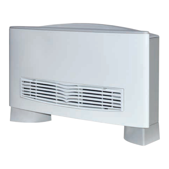
VENTILCONVETTORE
CON TERMOSTATO ELETTRONICO
FAN COIL
FOR UNIVERSAL INSTALLATION
WITH ELECTRONIC THERMOSTAT
VENTILO-CONVECTEUR
MUNI DE THERMOSTAT ÉLECTRONIQUE
GEBLÄSEKONVEKTOR
MIT ELEKTRONISCHEM THERMOSTAT
FAN COIL
PARA INSTALACIÓN UNIVERSAL
CON TERMOSTATO ELECTRÓNICO
Omnia HL N
Omnia HL 11 N
Omnia HL 16 N
Omnia HL 26 N
Omnia HL 36 N
Please fill out the requested information
Please fill out the requested information
M A N U A L E
D ' U S O
U S E
A N D
I N S T A L L A T I O N
MANUEL D'UTILISATION ET D'INSTALLATION
BEDIENUNGS- UND INSTALLATIONSANLEITUNG
MANUAL DE INSTRUCCIONES E INSTALACIÓN
PER INSTALLAZIONE UNIVERSALE
POUR INSTALLATION UNIVERSELLE
FÜR UNIVERSELLEN EINBAU
IHLNLJ 2302 - C6887213_01
E
I N S T A L L A Z I O N E
M A N U A L
Advertisement
Chapters

Subscribe to Our Youtube Channel
Related Manuals for AERMEC Omnia HL 11 N


Summary of Contents for AERMEC Omnia HL 11 N
- Page 1 MIT ELEKTRONISCHEM THERMOSTAT FAN COIL PARA INSTALACIÓN UNIVERSAL CON TERMOSTATO ELECTRÓNICO Omnia HL N Omnia HL 11 N Omnia HL 16 N Omnia HL 26 N Omnia HL 36 N Please fill out the requested information Please fill out the requested information...
-
Page 2: Remarks
Alle in diesem Handbuch enthaltenen Informationen für die Garantiearbeiten als erforderlich erweisen sollten. aufmerksam und vollständig lesen. Insbesondere auf die Die AERMEC S.p.A. übernimmt keine Haftung für Schäden aus dem Benutzungsanweisungen mit den Hinweisen "VORSICHT" oder unsachgemäßen Gebrauch des Gerätes und der teilweisen oder "ACHTUNG"... -
Page 3: Table Of Contents
Sommario Funktionen der Bedientafel ....................72 osservazioni ..........................2 GEBRAUCH ..........................73 Remarks ..........................2 Leuchtanzeigen für den Benutzer (Standardkonfiguration) ......74 Remarques ..........................2 SOLLWERT - EINSTELLUNGSBEISPIEL................74 Hinweise ..........................2 BETRIEBSWEISE ........................75 observaciones........................2 BESCHREIBUNG DER EINHEIT ..................77 trasporto • carriage • transport • transport • transporte ......... 4 Korrekturfaktoren für den Betrieb mit einer Wasser-Glykol-Mischung ..78 simboli di sicurezza •... - Page 4 TRASPORTO • CARRIAGE • TRANSPORT • TRANSPORT • TRANSPORTE NON bagnare • Do NOT wet NON calpestare • Do NOT trample CRAINT l’humidité • Vor Nässe schützen NE PAS marcher sur cet emballage • Nicht betreten NO mojar NO pisar Sovrapponibilità: controllare sull’imballo la sovrapponibilità...
- Page 5 Desideriamo complimentarci con Voi per l'acquisto del ventilconvettore OMNIA HL_N Aermec. Realizzato con materiali di qualità superiore, nel rigoroso rispetto delle normative di sicurezza, "OMNIA HL_N" è di facile utilizzo e vi accompagnerà a lungo nell'uso. INDICE Informazioni importanti • Imballo Manutenzione •...
- Page 6 INFORMAZIONI IMPORTANTI ATTENZIONE: I ventilconvettori mento, l’energia delle scariche elet- sul ventilconvettore durante il fun- OMNIA sono concepiti per fun- trostatiche non può né raggiungere, zionamento, altrimenti la polvere zionare in ambienti interni. né danneggiare le parti sensibili. presente nell'aria andrà a sporcare Se si effettuano misurazioni le superfici della batteria.
-
Page 7: Problemi E Soluzioni
Servizi essere più frequente; consiste consiste in una serie di operazioni Assistenza Aermec oppure da sog- nella pulizia della batteria, delle semplici, grazie alle quali il ventil- getti in possesso dei requisiti tec- coclee smontabili, delle alette del convettore può... -
Page 8: Funzioni Del Pannello Comandi
FUNZIONI DEL PANNELLO COMANDI La ventilazione è consentita solo con l’aletta aperta, è necessario aprirla manualmente. La chiusura dell’aletta provoca lo spegnimento della ventilazione. Per accedere al pannello comandi sollevare lo sportello di protezione. Chiudendo l’aletta del ventilconvet- tore master la scheda del termostato elettronico e gli altri ventilconvettori della rete continuno a funzionare. -
Page 9: Uso
Accensione - Per avviare il ventilconvettore ruotare la manopola e scegliere una velocità di ventilazione. AUTO - Per spegnere il ventilconvettore ruotare la manopola fino alla posizione Il ventilconvettore è spento. Nella condizione di spento il termostato continua a funzionare. Qualora la temperatura ambiente scenda sotto i 7°C e le condizioni di impianto lo consentano, il termostato attiverà... -
Page 10: Visualizzazioni Luminose Per L'utente (Configurazione Standard)
VISUALIZZAZIONI LUMINOSE PER L’UTENTE (CONFIGURAZIONE STANDARD) Il LED D indica la richiesta di ventilazione: BIANCA - (Acceso) Le condizioni ambientali richiedono il funzionamento del ventilatore (quando il selettore di velocità è in posizione AUTO, V1, V2, V3). AUTO - (Spento) Le condizioni ambientali non richiedono il funzionamento del ventilconvettore oppure il selettore è... -
Page 11: Funzionamento
FUNZIONAMENTO Il ventilconvettore OMNIA HL_N concen- (eseguibile solo da personale specializ- cità di ventilazione. tra elevate caratteristiche tecnologiche zato) consentono di eseguire una pulizia Le impostazioni fatte sul pannello coman- e funzionali che ne fanno il mezzo idea- accurata anche delle parti interne, condi- di possono essere trasmesse (senza le di climatizzazione per ogni ambiente. - Page 12 ne AUTO. La velocità del ventilatore è tuare un controllo più accurato sulla master sia chiuso tutti i fan coil slave gestita dal termostato in funzione delle temperatura ambiente, l’apertura della della rete vengono spenti. condizioni ambientali e della configura- valvola è...
-
Page 13: Descrizione Dell'unità
DESCRIZIONE DELL’UNITÀ SCOPO DELL'UNITÀ Il ventilconvettore è un terminale per il trattamento dell’aria di un ambiente sia nella stagione invernale sia in quella estiva. Versioni Omnia HL_N Ventilconvettore con mobile per installazione universale, dotato di termostato elettronico multifunzione può essere installato come unità... -
Page 14: Fattori Di Correzione Nel Funzionamento Con Acqua Glicolata
FAT T O R I D I C O R R E Z I O N E N E L F U N Z I O N A M E N T O C O N A C Q U A G L I C O L ATA Legenda: Perdite di carico Portata... -
Page 15: Componenti Principali
COMPONENTI PRINCIPALI 1 Pannello di comando (HL N) 7 Motore ventilatore 2 Scheda elettronica 8 Ventilatore 3 Mobile di copertura 9 Bacinella 4 Zoccoli (accessorio serie ZH) 10 Batteria di scambio termico 5 Struttura portante 11 Testata con alette orientabili 6 Filtro aria OMNIA HL_N DESCRIZIONE DEI COMPONENTI... - Page 16 INSTALLAZIONE ATTENZIONE: I ventilconvettori - Misura della resistenza di isolamento irrimediabilmente gli scambiatori di calore dell’impianto elettrico. in rame-alluminio o i componenti interni in OMNIA sono concepiti per funzio- - Prova della continuità dei conduttori di plastica. nare in ambienti interni. protezione.
- Page 17 INSTALLAZIONE DELL’UNITÀ - Togliere il mantello svitando le viti. scatola applicata alla fiancata, (vedi - Nella installazione a parete, si capitolo “IMPOSTAZIONI DIP-SWITCH”). mantenga una distanza minima - Eseguire tutti i collegamenti. dal pavimento di 80 mm. In caso di - Rimontare l’involucro.
- Page 18 COLLEGAMENTI E’ necessario che le condutture dell’acqua, dello scarico condensa e il circuito elettrico siano già stati previsti. COLLEGAMENTI IDRAULICI - Effettuare i collegamenti idraulici. La posizione e il diametro degli per evitare gocciolamenti durante il Per facilitare lo sfiato dell’aria dalla attacchi idraulici sono riportati nei dati funzionamento in raffreddamento.
- Page 19 COLLEGAMENTI ALLA SCHEDA ELETTRONICA Legenda dei collegamenti: L - N = Alimentazione elettrica SP = Non presente MS = Microswitch 230 Vac - 50 Hz Connettore tipo edge SW = Sonda acqua Morsetti a vite Pannello Comandi - TTL = Seriale Ingresso analogico Sezione minima cavo = 0,5 mm Connettore tipo faston...
- Page 20 IMPOSTAZIONI DIP-SWITCH Togliere tensione all’unità. Operazione da eseguire in fase di installazione solo da personale specializzato. I Dip-Switch si trovano sulla scheda elettronica. Agendo sui Dip-Switch otterremo le seguenti funzionalità: Dip 1 (Default OFF) Dip 5 (Default OFF) Controllo valvola acqua: Impostazione di fabbrica ❑...
- Page 21 Congratulations on your purchase of the Aermec OMNIA HL_N fan coil. Made with materials of superior quality in strict compliance with safety regulations, "OMNIA HL_N" is easy to use and will have a long life. CONTENTS Important information • Package Maintenance •...
-
Page 22: Important Information
IMPORTANT INFORMATION IMPORTANT: OMNIA fan coils electrostatic charges cannot the fan coil during operation (oth- are designed for indoor use. reach or damage the sensitive erwise dust in the air could soil the parts. coil surface area). IMPORTANT: the fan coil is con- Before taking measurements on the nected to power supply and WHAT IS NORMAL... -
Page 23: Maintenance
Extraordinary maintenance can only degree of air cleaning is required; out by the user: it involves a series be performed by Aermec After- it consists of cleaning the coil, the of simple operations, thanks to Sales Services or by people with... -
Page 24: Control Panel Functions
CONTROL PANEL FUNCTIONS Ventilation is only allowed with the fin open; it must be manually opened. The closure of the fin causes ventila- tion to switch off. To access the control panel, lift the protection flap. Closing the master fan coil fin, the electronic thermostat card and the other fan coils in the network will carry on working. -
Page 25: Use
Starting - To start up the fan coil, turn the knob and choose a ventilation speed. - To switch off the fan coil, turn the knob to the position AUTO The fan coil is switched off. In the OFF condition, the thermostat carries on working. If the room temperature falls below 7°C, and the system conditions allow it, the thermostat will activate ventilation (anti-freeze function). -
Page 26: Indicator Lights For The User (Standard Configuration)
INDICATOR LIGHTS FOR THE USER (STANDARD CONFIGURATION) LED D indicates a ventilation request: WHITE - (ON) The ambient conditions require the use of the fan (when the speed selector is on AUTO, V1, V2, V3). - (OFF) The ambient conditions do not require the use of the fan, or AUTO the selector is in the OFF (standby) position, or the fin is closed - (slow flashing) Operation mode managed by the centralised... -
Page 27: Operation
OPERATION The OMNIA HL_N fan coil concentrates (by specifically trained personnel), The settings made on the control panel hi-tech and highly functional featur- essential for installations in venues sub- can be transmitted (without additional esthat make it the ideal means of cli- ject to crowding or in those with special interfaces) to a network with up to 5 fan mate control in every room. - Page 28 point, the fan will switch off. positioned downstream or upstream problem and enable an emergency pro- - Modulated output thermostat. With from the shutoff valve, so also the dip- gram to avoid any inconvenience for the the selector on AUTO. The fan makes switches on the card must be set.
-
Page 29: Description Of The Unit
DESCRIPTION OF THE UNIT AIM OF THE UNIT The fan coil is a room air treatment terminal unit for both winter and summer operation. Versions Omnia HL_N A fan coil with cabinet, for universal installation and fitted with a multifunction electronic thermostat. It can be installed as an autonomous unit or within a network: it can, in fact, manage a network of a further 5 fan coils*. -
Page 30: Correction Factors When Operating Us In Glycol Water
C O R R E C T I O N F A C T O R S W H E N O P E R A T I N G G L Y C O L W A T E R Key: Pressure drops Air flow rate... -
Page 31: Main Components
MAIN COMPONENTS 1 Control panel (HL N) 7 Fan motor 2 Electronic card 8 Fan 3 Cabinet 9 Basin 4 Feet (accessory ZH) 10 Heat exchange coil 5 Load-bearing structure 11 Head with adjustable fins 6 Air filter OMNIA HL_N DESCRIPTION OF COMPONENTS CONTROL PANEL ium fans, held in place by means of the... -
Page 32: Installation Information
INSTALLATION In the specific case of electrical wirings, the damage to the copper-aluminium heat IMPORTANT: OMNIA fan coils are following must be checked: exchangers or internal plastic components. designed for indoor use. - Measurement of the electrical system Do not install the unit in workshops or insulation strength kitchens, where oil vapours mixed with the IMPORTANT: check that the power... -
Page 33: Installation
UNIT INSTALLATION - Loosen the screws to remove the the box on the side (see “DIP-SWITCH housing. SETTINGS”). - With wall-mounted units, keep a - Make all the connections. minimum clearance of 80mm from the - Reassemble the casing. floor. With floor-standing units on feet, - Make sure the fan coil is working refer to the instructions supplied with properly. -
Page 34: Water Connections
CONNECTIONS The water, condensate discharge and electrical circuit ducts must be provided for. WATER CONNECTIONS - Make the water connections. To help proper functioning of the unit. water lines, or fit the auxiliary the bleeding of air from the coil, you The position and diameter of the condensate drain tray (available are advised to connect the water... -
Page 35: Connections To The Electronic Card • Network Settings
CONNECTIONS TO THE ELECTRONIC CARD Connections key: L - N = Power supply SA = SA Air probe MS = Microswitch 230 Vac - 50 Hz Analogue input Edge-type connector Screw clamps Removable-type connector Control panel - TTL = Local serial TTL Minimum cable section = 0.5mm Maximum cable length = 3 m Removable-type connector... -
Page 36: Dip-Switch Settings • Filter Installation And Replacement
DIP-SWITCH SETTINGS Turn off the power to the unit. This operation should be carried out in the installation phase, by suitably trained and qualified personnel only. The dip-switches are on the electronic card. They can be used to obtain the following functions: Dip 1 (Default OFF) Dip 5 (Default OFF) Water valve check:... - Page 37 Veuillez accepter nos compliments les plus sincères pour avoir acheté le ventilo-convecteur OMNIA HL_N Aermec. Réalisé avec des matériaux de première qualité, dans le plus grand respect des normes de sécurité, "OMNIA HL_N" est facile à utiliser et destiné à durer longtemps.
-
Page 38: Informations Importantes
INFORMATIONS IMPORTANTES AT TENTION: Les ventilo - atteindre, et donc détruire, les par- salir la surface de la batterie. convecteurs OMNIA ont été ties sensibles. IL EST NORMAL conçus pour fonctionner à l'inté- Si on effectue des mesures sur Pendant le fonctionnement en mode rieur. -
Page 39: Entretien
être effectué que par les services Interventions : Interventions : après vente Aermec ou bien par - Nettoyage extérieur, fréquence - Nettoyage intérieur, une fois par des personnes possédant les hebdomadaire, à effectuer avec an ou avant tout arrêt de longue... -
Page 40: Fonctions Du Panneau De Commande
FONCTIONS DU PANNEAU DE COMMANDE La ventilation n'est permise qu'avec l'ailette ouverte, il faut l'ouvrir manuellement. La fermeture de l'ailette provoque l'extinction de la ventilation. Pour accéder au panneau de com- mande, soulever la porte de protec- tion. En fermant l'ailette du ventilocon- vecteur maître, la carte du thermos- tat électronique et les autres ventilo- convecteurs du réseau continuent à... -
Page 41: Utilisation
UTILISATION Mise en marche - Pour démarrer le ventilo-convecteur, tourner la molette et choisir une vitesse de ventilation. AUTO - Pour éteindre le ventilo-convecteur, tourner la molette jusqu'à la position Le ventilo-convecteur est éteint. Même lorsque le ventilo-convecteur est éteint, le thermostat continue à fonctionner. -
Page 42: Affichages Lumineux Pou R L'utilisateur (Réglage Ordinaire)
AFFICHAGES LUMINEUX POU R L'UTILISATEUR (RÉGLAGE ORDINAIRE) La DEL D indique la demande de ventilation : BLANC - (allumée) Les conditions environnementales exigent le fonctionnement du ventilateur (lorsque le sélecteur de vitesse est en position AUTO, V1, V2, V3). AUTO - (Éteint) Les conditions environnementales n'exigent pas le fonctionnement du ventilo-convecteur, ou le sélecteur est en position OFF (veille), ou bien l'ailette est fermée. -
Page 43: Fonctionnement
FONCTIONNEMENT d'inspection (opération qui ne peut être pour régler la vitesse de ventilation. Le ventilo-convecteur OMNIA HL_N réu- nit des caractéristiques technologiques effectuée que par du personnel spécia- Les réglages réalisés sur le panneau de et fonctionnelles élevées qui en font le lisé) permet d'effectuer un nettoyage commande peuvent être transmis (sans moyen de climatisation idéal pour tous... - Page 44 • Ventilation tures et fermetures de la vanne, en faisant de ventilo-convecteurs, seul le contact circuler de l'eau chaude dans le ventilo- extérieur du ventilo-convecteur maître est La ventilation à trois vitesses peut être convecteur, sur demande du thermostat, la activé.
-
Page 45: Description De L'unité
DESCRIPTION DE L'UNITÉ OBJET DE L'UNITÉ Le ventilo-convecteur est un terminal pour le traitement de l’air d’un milieu, tant en hiver qu’en été. Versions Omnia HL_N Ventilo-convecteur avec carosserie pour installation universelle, doté de thermostat électronique multifonction, qui peut être installé... -
Page 46: Facteurs De Correction Dans Le Fonctionnement Avec Eau Glycolée
FAC T E U R S D E CO R R E C T I O N D A N S L E F O N C T I O N N E M E N T AV E C E AU G LYCO L É E Légende: Pertes de charge Débit... -
Page 47: Composants Principaux
COMPOSANTS PRINCIPAUX 1 Panneau de commande (HL N) 7 Moteur du ventilateur 2 Carte électronique 8 Ventilateur 3 Meuble de couverture 9 Bac 4 Socles (accessoire de série ZH) 10 Batterie d'échange thermique 5 Structure portante 11 Tête avec ailettes orientables 6 Filtre à... -
Page 48: Instalation
INSTALATION ATTENTION: Les ventilo-convec- sont requises pour les branchements e n d o m m a g e r i r r é p a r a b l e m e n t l e s teurs OMNIA ont été conçus pour électriques : échangeurs de chaleur en cuivre-aluminium fonctionner à... -
Page 49: Installation De L'unité • Rotation De La Batterie
INSTALLATION DE L'UNITÉ - Dévisser les vis de la couverture puis commutateurs DIP dans la fenêtre l'enlever. respective du boîtier situé sur le - En cas d'installation murale, il faut flanc (voir le chapitre “RÉGLAGES DES maintenir une distance minimale au COMMUTATEURS DIP”). -
Page 50: Raccords Hydrauliques
RACCORDEMENTS Il est nécessaire que les conduites d'eau, d'évacuation des condensats ainsi que du circuit électrique aient déjà été prévues. RACCORDS HYDRAULIQUES - Effectuer les raccords hydrauliques. La position et le diamètre des raccords disponible comme accessoire, pour Pour faciliter la purge de l'air hydrauliques sont reportés dans les éviter des écoulements pendant de la batterie, il est conseillé... -
Page 51: Branchements À La Carte Électronique • Réglages Du Réseau
BRANCHEMENTS À LA CARTE ÉLECTRONIQUE Légende des branchements: L - N = Alimentation électrique FUSE = Fusible de protection MS = Microrupteur 230 Vac ~ 50 Hz Fusible de 2 A retardé Connecteur encartable Bornes à vis SA = SA sonde d'air Panneau de Commande - TTL = Série Section minimale du câble = 0,5 mm Entrée analogique... -
Page 52: Réglages Des Commutateurs Dip • Installation Et Remplacement Du Filtre
RÉGLAGES DES COMMUTATEURS DIP Couper la tension de l’unité. Cette opération doit être menée en phase d'installation exclusivement par du personnel spécialisé. Les commutateurs DIP se trouvent sur la carte électronique. En agissant sur les commutateurs DIP, on obtient les fonctions suivantes: Dip 1 (par défaut OFF) Dip 5 (par défaut OFF) - Page 53 Wir möchten Sie zum Kauf des Gebläsekonvektors OMNIA HL_N von Aermec beglückwünschen. Aus Materialien von hoher Qualität und unter genauer Einhaltung der Sicherheitsbestimmungen hergestellt, lässt sich "OMNIA HL_N" einfach benutzen und wird Sie lange Zeit im Gebrauch begleiten. INHALTSVERZEICHNIS Wichtige Hinweise • Verpackung Wartung •...
-
Page 54: Wichtige Hinweise • Verpackung
WICHTIGE HINWEISE A C H T U N G : D i e O M N I A elektrostatischen Entladungen die demzufolge Unwohlsein auslösen. Gebläsekonvektoren sind für den empfindlichen Teile nicht erreichen WÄHREND DES BETRIEBS Betrieb in Innenräumen konzipiert. oder beschädigen. Lassen Sie während des Betriebs Wenn Messungen am Gerät durch- A C H T U N G :... -
Page 55: Wartung • Probleme Und Lösungen
Benutzer ausgeführt werden. nur von einer Kundendienststelle - Innere Reinigung ( jährlich oder Sie besteht in der Ausführung ver- Aermec bz w. von qualifizier- vor längerem Gerätestillstand); schiedener einfacher Eingriffe, die ten Technikern ausgeführt wer- R ä u m e n... -
Page 56: Funktionen Der Bedientafel
FUNKTIONEN DER BEDIENTAFEL Die Lüftung ist nur bei offener Lamelle zulässig, die manuell zu öffnen ist. Schließt man die Lamelle, schaltet sich die Lüftung aus. Für den Zugriff auf die Bedientafel die Schutzklappe anheben. Schließt man die Lamelle des Master-Gebläsekonvektors blei- ben die Platine des elektronischen Thermostats und die anderen in Netzschaltung verbundenen... -
Page 57: Gebrauch
GEBRAUCH Einschalten - Zum Anstarten des Gebläsekonvektors den Griff drehen und eine Gebläsedrehzahl auswählen. AUTO - Zum Ausschalten des Gebläsekonvektors den Griff bis in die Stellung drehen . Der Gebläsekonvektor ist ausgeschaltet. Im ausgeschalteten Zustand bleibt der Thermostat weiterhin in Betrieb. Sollte die Raumtemperatur unter 7°C absinken und der Zustand der Anlage es zulassen, aktiviert der Thermostat die Lüftung (Frostschutzfunktion). -
Page 58: Ansichten Für Den Bediener
LEUCHTANZEIGEN FÜR DEN BENUTZER (STANDARDKONFIGURATION) LED D zeigt die Lüftungsansteuerung an: WEISS - (Eingeschaltet) Die Raumbedingungen er fordern den Gebläsebetrieb (bei Stellung des Drehzahlwahlschalters auf AUTO, V1, V2, V3). AUTO - (Ausgeschaltet) Die Raumbedingungen erfordern nicht den Betrieb des Gebläsekonvektors oder der Wahlschalter steht auf OFF (Stand-by) oder die Lamelle ist geschlossen - (Langsames Blinken) Betriebsart, die von der Zentralsteuerung gesteuert wird. -
Page 59: Betriebsweise
BETRIEBSWEISE Der Gebläsekonvektor OMNIA HL_N Durch die Möglichkeit, die Wanne und senken, den anderen zum Ein- und ist ein Konzentrat aus erstklassigen die Ventilatorschaufeln abzunehmen Ausschalten und zur Einstellung der technologischen und funktionellen (nur durch Fachpersonal ausführbar), Gebläsedrehzahl. Eigenschaften, wodurch er sich für ist auch eine sorgfältige Reinigung Die Einstellungen, die an der Bedientafel die Klimatisierung eines jeden Raums... - Page 60 • Mikroschalterkontakt Einstellungen des Thermostats: W a s s e r t e m p e r a t u r f ü h l e r - 3 - s t u f i g e r T h e r m o s t a t . M i t Wärmetauscher ausgestattet.
-
Page 61: Beschreibung • Technische Daten Und Betriebsgrenzen
BESCHREIBUNG DER EINHEIT ZWECK DES GERÄTS Der Gebläsekonvektor ist eine Endeinheit für die Raumluftbehandlung sowohl für den Winter- als auch den Sommerbetrieb. Versionen Omnia HL_N Gebläsekonvektor mit Verkleidung für universellen Einbau, ausgestattet mit elektronischem Multifunktions-Thermostat, installierbar als eigenständiges Gerät oder in Netzschaltung mit bis zu 5 anderen Gebläsekonvektoren*. * Die in Netzschaltung verbundenen Gebläsekonvektoren müssen voreingestellte Modelle sein oder mit entsprechenden Zubehörteilen ausgestattet sein. -
Page 62: Korrekturfaktoren Für Den Betrieb Mit Einer Wasser-Glykol-Mischung
KO R R E K T U R FA K TO R E N F Ü R D E N B E T R I E B M I T E I N E R WA S S E R - G LYKO L - M I S C H U N G Legende: Druckverluste Durchfluß... -
Page 63: Hauptkomponenten • Beschreibung Der Komponenten
HAUPTKOMPONENTEN 1 Bedientafel (HL N) 7 Motor des Ventilators 2 Platine 8 Ventilator 3 Verkleidung 9 Wanne 4 Sockel (Zubehörteil Serie ZH) 10 Wärmetauscher 5 Trägerstruktur 11 Kopfteil mit schwenkbaren Lamellen 6 Luftfilter OMNIA HL_N BESCHREIBUNG DER KOMPONENTEN BEDIENTAFEL Das Gehäuse besteht aus verz i n k t e m S durch Verzinkung gegen Oxidation Die Bedientafel befindet sich geschützt t a h l b l e c h m i t... -
Page 64: Hinweise Zur Installation
INSTALLATION A C H T U N G : D i e O M N I A müssen folgende Prüfungen durchgeführt Innenteile aus Kunststoff unwiederbringlich werden: beschädigen könnten. Gebläsekonvektoren sind für den - Messung des Isolationswiderstandes der Das Gerät nicht in Werkstätten oder Betrieb in Innenräumen konzipiert. -
Page 65: Installation Des Geräts • Drehung Des Wärmetauschers
INSTALLATION DER EINHEIT - den Mantel durch Ausschrauben der - Zur Änderung der Einstellungen des Schrauben entfernen. elektronischen Thermostats an den - b e i Wa n d i n s t a l l a t i o n i s t e i n e Dip-Schaltern über die entsprechende B o d e n h ö... -
Page 66: Wasseranschlüsse
ANSCHLÜSSE Die Wasserleitungen, der Kondensatablauf und die elektrischen Leitungen müssen bereits vorbereitet sein. WASSERANSCHLÜSSE - Nehmen Sie die Hydraulikanschlüsse Gerätebetrieb keineswegs. Kondensatwanne zu installieren, um v o r. U m d a s E n t l ü f t e n d e s Po s i t i o n u n d Q u e r s c h n i t t e d e r zu vermeiden, dass während des Austauschers zu vereinfachen, ist... -
Page 67: Anschlüsse An Die Elektronikkarte • Netzeinstellungen
ANSCHLÜSSE AN DIE ELEKTRONIKKARTE Legende der Anschlüsse: L - N = Stromversorgung SA = SA Lufttemperaturfühler MS = Mikroschalter 230 Vac - 50 Hz Analoger Eingang Edge-Verbinder Schraubklemmen Ausziehbarer Stecker Bedientafel - TTL = Seriell Lokal TTL Kleinster Kabelquerschnitt = 0,5 mm Maximale Kabellänge = 3 m Ausziehbarer Stecker Größter Kabelquerschnitt = 2,0 mm... -
Page 68: Einstellungen Der Dip-Schalter • Filtereinbau Und Filtertausch
EINSTELLUNGEN DIP-SCHALTER Die Spannungszufuhr zur Einheit unterbrechen. Dieser Arbeitsschritt ist während der Installation und nur von Fachpersonal auszuführen. Die Dip-Schalter befinden sich auf der Elektronikkarte. Über die Dip-Schalter werden folgende Funktionsweisen erzielt: Dip 1 (Standard OFF) Dip 5 (Standard OFF) Kontrolle des Wasserventils: Werkseinstellung ❑... -
Page 69: Indice
Deseamos felicitarles por la compra del fan coil OMNIA HL_N Aermec. Realizado con materiales de calidad superior y mostrando un riguroso respeto a las normativas de seguridad, "OMNIA HL_N" se caracteriza por su fácil manejo y les acompañará durante mucho tiempo en su uso. -
Page 70: Informaciones Importantes
INFORMACIONES IMPORTANTES ATENCIÓN: Los fan coils OMNIA ES NORMAL ticas no puede alcanzar o dañar las han sido diseñados para fun- partes sensibles. Durante el funcionamiento en cionar en ambientes interiores. Si se realizan mediciones en la uni- frío puede salir vapor de agua por el dad se deben, antes de realizar las canal de envío del fan coil. -
Page 71: Mantenimiento
Servicios de ción prolongada; en lugares nes simples, que permiten al fan Asistencia Aermec, o por alguien donde se necesite un alto grado coil funcionar con la máxima efi- que reúna los requisitos técnico- de limpieza del aire, puede reali- cacia. -
Page 72: Funciones Del Tablero De Mandos
FUNCIONES DEL TABLERO DE MANDOS La ventilación es posible sólo con la aleta abierta, es necesario abrir- la manualmente. El cierre de la aleta da lugar al apaga- do de la ventilación. Para acceder al tablero de mandos, levantar la tapa de protección. Si se cierra la aleta del fan coil mas- ter, la tarjeta del termostato electró- nico y los demás fan coils de la red... -
Page 73: Uso
Encendido - Para encender el fan coil, gire el mando y seleccione una velocidad de ventilación. - Para apagar el fan coil, gire el mando hasta la posición AUTO El fan coil está apagado. En la condición de apagado, el termostato continúa funcionando. Cuando la temperatura ambiente descienda por debajo de los 7°C y las condiciones de la instalación lo permitan, el termostato activará... -
Page 74: Indicaciones Luminosas Para El Usuario (Configuración Estándar )
INDICACIONES LUMINOSAS PARA EL USUARIO (CONFIGURACIÓN ESTÁNDAR ) El LED D indica la solicitud de ventilación: BLANCO - (Encendido) Las condiciones ambientales requieren el funcionamiento del ventilador (cuando el selector de velocidad está en posición AUTO, V1, V2, V3). AUTO - (Apagado) Las condiciones ambientales no requieren el funcionamiento del fan coil o el selector está... -
Page 75: Funcionamiento
FUNCIONAMIENTO llos de los ventiladores inspeccionables tura, el segundo para encender/apagar El fan coil OMNIA HL_N reúne elevadas características tecnológicas y funciona- (operación realizada sólo por personal y configurar la velocidad de ventilación. les que lo convierten en el medio ideal experto) es posible limpiar profunda- Las configuraciones que se realicen en para climatizar cualquier ambiente. - Page 76 de la configuración del fan coil. de la válvula está desfasada respecto a cerrada, todos los fan coils slave de la Configuraciones del termostato: la ventilación. red se apagan. - Termostato de 3 niveles. Con el selec- • Sonda de agua •...
-
Page 77: Descripción De La Unidad
DESCRIPCIÓN DE LA UNIDAD OBJETIVO DE LA UNIDAD El fan coil es un terminal para el tratamiento del aire de un ambiente tanto en invierno como en verano. Versiones Omnia HL_N Fan coil con mueble para la instalación universal, equipado con termostato electrónico multifunción, que puede instalarse como unidad autónoma o en red, de hecho puede controlar una red de 5 fan coils*. -
Page 78: Factores De Corrección En El Funcionamiento Con Agua Glicolada
FA C TO R E S D E CO R R E CC I Ó N E N E L F U N C I O N A M I E N TO CO N A G UA G L I CO L A D A Leyenda: Pérdidas de carga Caudal... -
Page 79: Componentes Principales
COMPONENTES PRINCIPALES 1 Tablero de mando (HL N) 7 Motor ventilador 2 Tarjeta electrónica 8 Ventilador 3 Mueble de cobertura 9 Cubeta 4 Zócalos (accesorio de serie ZH) 10 Batería de intercambio térmico 5 Estructura portante 11 Parte superior con aletas orientables 6 Filtro del aire OMNIA HL_N DESCRIPCIÓN DE LOS COMPONENTES... - Page 80 INSTALACIÓN ATENCIÓN: Los fan coils OMNIA necesario comprobar : ácidas o alcalinas que puedan dañar - Medición de la resistencia de aislamiento irremediablemente los intercambiadores de han sido diseñados para funcionar de la instalación eléctrica. calor de cobre -aluminio o los componentes en ambientes interiores.
- Page 81 INSTALACIÓN DE LA UNIDAD - Quitar la cubierta desenroscando los correspondiente de la caja aplicada tornillos. al lateral , ( véase el capítulo - En la instalación en pared, disponer “CONFIGURACIÓN DIP-SWITCH”). una distancia mínima de 80 mm del - Realice todas las conexiones. suelo.
- Page 82 CONEXIONES Es necesario que las tuberías del agua, de la descarga del agua de condensación y el circuito eléctrico hayan sido previstas. Conexiones hidráulicas - Realice las conexiones hidráulicas. funcionamiento normal de la unidad. de condensadas auxiliar (disponible Para facilitar la ventilación de La posición y el diámetro de las como accesorio) para evitar el goteo la batería, se aconseja conectar el...
- Page 83 CONEXIONES A LA TARJETA ELECTRÓNICA Leyenda de las conexiones: L - N = Alimentación eléctrica SA = SA Sonda aire MS = Microswitch 230 Vac - 50 Hz Entrada analógica Conector tipo edge Bornes de tornillo Conector tipo extraíble Tablero de mandos - TTL = Serial Local TTL Sección mínima del cable = 0,5 mm Longitud máxima del cable = 3 m Conector tipo extraíble...
- Page 84 PROGRAMACIÓN DIP-SWITCH Quitar la tensión a la unidad. Las operaciones se deben realizar en la fase de instalación y sólo por personal especializado. Los Dip-Switch se encuentran en la tarjeta electrónica. A través de los Dip-Switch se obtendrán las siguientes funciones: Dip 1 (Defecto OFF) Dip 5 (Defecto OFF)
-
Page 85: Dimensions
DIMENSIONI • DIMENSIONS • ABMESSUNGEN • DIMENSIONES [mm] 1 0 0 Mod Omnia HL 16 HL 26 HL 36 Larghezza • Width • Largeur • Breite • Longitud 1200 Altezza • Height • Hauteur • Höhe • Altura Profondità • Depth • Profondeur • Tiefe • Profundidad Altezza zoccoli •... - Page 86 DIMENSIONI • DIMENSIONS • ABMESSUNGEN • DIMENSIONES [mm] 1 Testata con alette orientabili 2 Mobile di copertura 3 Struttura portante 4 Zoccolo ZH 5 Spazio per i collegamenti 1 Head with adjustable fins 2 Cabinet 3 Load-bearing structure 4 Foot ZH 5 Space for connections 1 Tête avec ailettes orientables 2 Carosserie de protection...
-
Page 87: Schémas Électriques
SCHEMI ELETTRICI • WIRING DIAGRAMS • SCHEMAS ELECTRIQUES • ELEKTRISCHE SCHALTPLÄNE • ESQUEMAS ELECTRICOS LEGENDA • KEY • LEGENDE • LEGENDE • LEYENDA = Interruttore generale • Master switch • Interrupteur général • Hauptschalter • Interruptor general = Morsettiera • Control board • Bornier • Klemmleiste • Caja de conexiones = Microinterruttore •... - Page 88 SCHEMI ELETTRICI • WIRING DIAGRAMS • SCHEMAS ELECTRIQUES • ELEKTRISCHE SCHALTPLÄNE • ESQUEMAS ELECTRICOS LEGENDA • KEY • LEGENDE • LEGENDE • LEYENDA = Arancio = Orange = orange = Orange = Naranja = Bianco = White = blanc = Weiß = Blanco = Blu = Blue...
- Page 89 ATTENZIONE! Questo apparecchio è previsto per essere fissato alla parete o la soffitto. Qualora venga installato diversamente dovrà obbligatoriamente essere impiegato il pannello di coperturea fornito come accessorio . (norme EN 60335-1) WARNING! This application is designed for wall or ceiling installation.For other types of installation the beck panel accessory must be used. (standard 60335-1) ATTENTION! Cet appareil est conçu pour installation à...
- Page 90 Per evitare eventuali danni all’ambiente o alla salute umana causati dall’errato smaltimento dei Rifiuti Elettrici ed Elettronici (RAEE), si prega di restituire il dispositivo utilizzando gli opportuni sistemi di raccolta, oppure contattando il rivenditore presso il quale il prodotto è stato acquistato. This marking indicates that this product should not be disposed with other household wastes throughout the EU.
- Page 92 AERMEC S.p.A. si riserva la facoltà di apportare in qualsiasi momento tutte le modifiche ritenute necessarie per il miglioramento del prodotto. Les données mentionnées dans ce manuel ne constituent aucun engagement de notre part. Aermec S.p.A. se réserve le droit de modifier à tous moments les données considérées nécessaires à...
Need help?
Do you have a question about the Omnia HL 11 N and is the answer not in the manual?
Questions and answers