Advertisement
Available languages
Available languages
Quick Links
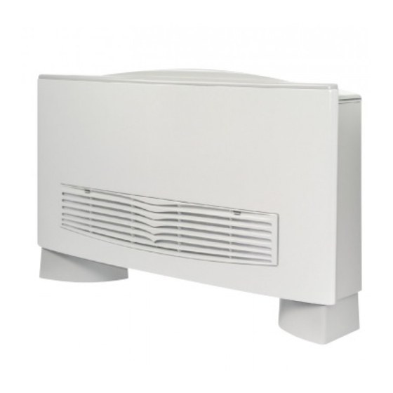
VENTILCONVETTORE
CON TERMOSTATO ELETTRONICO
FAN COIL
FOR UNIVERSAL INSTALLATION
WITH ELECTRONIC THERMOSTAT
VENTILO-CONVECTEUR
MUNI DE THERMOSTAT ÉLECTRONIQUE
GEBLÄSEKONVEKTOR
MIT ELEKTRONISCHEM THERMOSTAT
FAN COIL
PARA INSTALACIÓN UNIVERSAL
CON TERMOSTATO ELECTRÓNICO
Omnia HL N
Omnia HL 11 N
Omnia HL 16 N
Omnia HL 26 N
Omnia HL 36 N
Please fill out the requested information
Please fill out the requested information
M A N U A L E
D ' U S O
U S E
A N D
I N S T A L L A T I O N
MANUEL D'UTILISATION ET D'INSTALLATION
BEDIENUNGS- UND INSTALLATIONSANLEITUNG
MANUAL DE INSTRUCCIONES E INSTALACIÓN
PER INSTALLAZIONE UNIVERSALE
POUR INSTALLATION UNIVERSELLE
FÜR UNIVERSELLEN EINBAU
Omnia HL 11 NM
Omnia HL 16 NM
Omnia HL 26 NM
Omnia HL 36 NM
IHLNLJ 1711 - 6887212_01
E
I N S T A L L A Z I O N E
M A N U A L
Advertisement
Chapters

Related Manuals for AERMEC Omnia HL N Series


Summary of Contents for AERMEC Omnia HL N Series
- Page 1 M A N U A L E D ’ U S O I N S T A L L A Z I O N E U S E A N D I N S T A L L A T I O N M A N U A L MANUEL D’UTILISATION ET D’INSTALLATION BEDIENUNGS- UND INSTALLATIONSANLEITUNG...
-
Page 2: Osservazioni
Alle in diesem Handbuch enthaltenen Informationen auf- sich für die Garantiearbeiten als erforderlich erweisen sollten. merksam und vollständig lesen. Insbesondere auf die Die AERMEC S.p.A. übernimmt keine Haftung für Schäden aus Benutzungsanweisungen mit den Hinweisen "VORSICHT" oder dem unsachgemäßen Gebrauch des Gerätes und der teilweisen "ACHTUNG"... -
Page 3: Table Of Contents
Sommario Funktionen der Bedientafel ....................72 osservazioni ..........................2 GEBRAUCH ..........................73 Remarks ..........................2 Leuchtanzeigen für den Benutzer (Standardkonfiguration) ......74 Remarques ..........................2 SOLLWERT - EINSTELLUNGSBEISPIEL................74 Hinweise ..........................2 BETRIEBSWEISE ........................75 observaciones........................2 BESCHREIBUNG DER EINHEIT ..................77 trasporto • carriage • transport • transport • transporte ......... 4 Korrekturfaktoren für den Betrieb mit einer Wasser-Glykol-Mischung ..78 simboli di sicurezza •... -
Page 4: Trasporto • Carriage • Transport • Transport • Transporte
TRASPORTO • CARRIAGE • TRANSPORT • TRANSPORT • TRANSPORTE NON bagnare • Do NOT wet NON calpestare • Do NOT trample CRAINT l’humidité • Vor Nässe schützen NE PAS marcher sur cet emballage • Nicht betreten NO mojar NO pisar Sovrapponibilità: controllare sull’imballo la sovrapponibilità... -
Page 5: Indice
Desideriamo complimentarci con Voi per l'acquisto del ventilconvettore OMNIA HL_N Aermec. Realizzato con materiali di qualità superiore, nel rigoroso rispetto delle normative di sicurezza, "OMNIA HL_N" è di facile utilizzo e vi accompagnerà a lungo nell'uso. La serie OMNIA HL N è disponibile in due versioni cromatiche, la lettera “M” identifica solo la finitura cromatica con involu- cro grigio metallizato, le prestazioni e le funzioni sono identiche alle versioni con mobile bianco. -
Page 6: Informazioni Importanti
INFORMAZIONI IMPORTANTI ATTENZIONE: I ventilconvetto- elettrostatiche non può né raggiun- te il funzionamento, altrimenti la ri OMNIA sono concepiti per gere, né danneggiare le parti sen- polvere presente nell'aria andrà a funzionare in ambienti interni. sibili. sporcare le superfici della batteria. Se si effettuano misurazioni ATTENZIONE: il ventilconvetto- È... -
Page 7: Manutenzione
Servizi trostaticamente, frequenza quin- te; consiste nella pulizia della Assistenza Aermec oppure da dicinale o settimanale in caso batteria, delle coclee smonta- soggetti in possesso dei requisiti di installazione in ambienti con... -
Page 8: Funzioni Del Pannello Comandi
FUNZIONI DEL PANNELLO COMANDI La ventilazione è consentita solo con l’aletta aperta, è necessario aprirla manualmente. La chiusura dell’aletta provoca lo spegnimento della ventilazione. Per accedere al pannello comandi sollevare lo sportello di protezione. Chiudendo l’aletta del ventilconvet- tore master la scheda del termostato elettronico e gli altri ventilconvetto- ri della rete continuno a funzionare. -
Page 9: Uso
Accensione - Per avviare il ventilconvettore ruotare la manopola e scegliere una velocità di ventilazione. AUTO - Per spegnere il ventilconvettore ruotare la manopola fino alla posizione Il ventilconvettore è spento. Nella condizione di spento il termostato continua a funzionare. Qualora la temperatura ambiente scenda sotto i 7°C e le condizioni di impianto lo consentano, il termostato attiverà... -
Page 10: Visualizzazioni Luminose Per L'utente (Configurazione Standard)
VISUALIZZAZIONI LUMINOSE PER L’UTENTE (CONFIGURAZIONE STANDARD) Il LED D indica la richiesta di ventilazione: BIANCA - (Acceso) Le condizioni ambientali richiedono il funzionamento del ventilatore (quando il selettore di velocità è in posizione AUTO, V1, V2, V3). AUTO - (Spento) Le condizioni ambientali non richiedono il funzionamento del ventilconvettore oppure il selettore è... -
Page 11: Funzionamento
FUNZIONAMENTO Il ventilconvettore OMNIA HL_N con- La possibilità di rimuovere la bacinella per aumentare o diminuire la tempera- centra elevate caratteristiche tecno- e le coclee dei ventilatori ispezionabili tura, la seconda per accendere/spegnere logiche e funzionali che ne fanno il (eseguibile solo da personale specializ- e impostare la velocità... - Page 12 tà selezionata. la potenza frigorifera dell’unità ed master sia chiuso tutti i fan coil slave - Automatica, con selettore in posizione effettuare un controllo più accurato della rete vengono spenti. AUTO. La velocità del ventilatore è sulla temperatura ambiente, l’apertu- •...
-
Page 13: Descrizione Dell'unità
DESCRIZIONE DELL’UNITÀ SCOPO DELL'UNITÀ Il ventilconvettore è un terminale per il trattamento dell’aria di un ambiente sia nella stagione invernale sia in quella estiva. Versioni Omnia HL_N e OMNIA HL_NM Ventilconvettore con mobile per installazione universale, dotato di termostato elettronico multifunzione può essere installato come unità... -
Page 14: Fattori Di Correzione Nel Funzionamento Con Acqua Glicolata
FAT TO R I D I C O R R E Z I O N E N E L F U N Z I O NA M E N TO C O N AC QUA G L I C O L ATA Legenda: Perdite di carico Portata... -
Page 15: Componenti Principali
COMPONENTI PRINCIPALI 1 Pannello di comando (HL N) 7 Motore ventilatore 2 Scheda elettronica 8 Ventilatore 3 Mobile di copertura 9 Bacinella 4 Zoccoli (accessorio serie ZH) 10 Batteria di scambio termico 5 Struttura portante 11 Testata con alette orientabili 6 Filtro aria OMNIA HL_N DESCRIZIONE DEI COMPONENTI... -
Page 16: Installazione
FILTRO ARIA PRECARICATO ELETTROSTATICAMENTE = Filtro serie HL Aermec = Filtro standard per ventilconvettori 0 , 7 2 , 0 0 , 3 0 , 5 1 , 0 Diametro particelle [µm] INSTALLAZIONE ATTENZIONE: I ventilconvetto- dell’impianto elettrico. di calore in rame-alluminio o i - Prova della continuità... - Page 17 INSTALLAZIONE DELL’UNITÀ - Togliere il mantello svitando le viti. scatola applicata alla fiancata, (vedi - Nella installazione a parete, si capitolo “IMPOSTAZIONI DIP- mantenga una distanza minima dal SWITCH”). pavimento di 80 mm. In caso di - Eseguire tutti i collegamenti. installazione a pavimento per mezzo - Rimontare l’involucro.
- Page 18 COLLEGAMENTI E’ necessario che le condutture dell’acqua, dello scarico condensa e il circuito elettrico siano già stati previsti. COLLEGAMENTI IDRAULICI - Effettuare i collegamenti idraulici. La posizione e il diametro degli accessorio, per evitare gocciolamenti Per facilitare lo sfiato dell’aria dalla attacchi idraulici sono riportati nei d u r a n t e i l f u n z i o n a m e n t o i n batteria si consiglia di collegare il...
- Page 19 COLLEGAMENTI ALLA SCHEDA ELETTRONICA Legenda dei collegamenti: L - N = Alimentazione elettrica SP = Non presente MS = Microswitch 230 Vac - 50 Hz Connettore tipo edge SW = Sonda acqua Morsetti a vite Ingresso analogico Pannello Comandi - TTL = Seriale Sezione minima cavo = 0,5 mm Connettore tipo faston Locale TTL...
- Page 20 1 2 3 4 5 6 7 8 1 2 3 4 5 6 7 8 INSTALLAZIONE DEL FILTRO DELL’ARIA PRECARICATO ELETTROSTATICAMENTE • • presso i centri assistenza Aermec). Installazione Caratteristiche - Smontare la griglia di aspirazione Classe 2 (UL 900).
-
Page 21: Contents
The OMNIA HL N series is available in two chromatic versions, the letter “M” identifies only the chromatic finish with metallic gray casing, performance and functions are identical to the version with white casing. -
Page 22: Important Information
IMPORTANT INFORMATION IMPORTANT: OMNIA fan coils Before taking measurements In the cooling operation, water are designed for indoor use. on the unit, it is necessary to vapour may be present in the air discharge all electrostatic charges delivery of the fan coil. IMPORTANT: the fan coil is from your body. -
Page 23: Maintenance
Extraordinary maintenance can - Cleaning the electrostatically pre- required; it consists of cleaning only be performed by Aermec charged filter, every two weeks or the coil, the removable volute, After-Sales Services or by people... -
Page 24: Control Panel Functions
CONTROL PANEL FUNCTIONS Ventilation is only allowed with the fin open; it must be manually opened. The closure of the fin causes venti- lation to switch off. To access the control panel, lift the protection flap. Closing the master fan coil fin, the electronic thermostat card and the other fan coils in the network will carry on working. -
Page 25: Use
Starting - To start up the fan coil, turn the knob and choose a ventilation speed. - To switch off the fan coil, turn the knob to the position AUTO The fan coil is switched off. In the OFF condition, the thermostat carries on working. If the room temperature falls below 7°C, and the system conditions allow it, the thermostat will activate ventilation (anti-freeze function). -
Page 26: Indicator Lights For The User (Standard Configuration)
INDICATOR LIGHTS FOR THE USER (STANDARD CONFIGURATION) LED D indicates a ventilation request: WHITE - (ON) The ambient conditions require the use of the fan (when the speed selector is on AUTO, V1, V2, V3). - (OFF) The ambient conditions do not require the use of the AUTO fan, or the selector is in the OFF (standby) position, or the fin is closed... -
Page 27: Operation
OPERATION The OMNIA HL_N fan coil concentrates ensure thorough cleaning of the unit can be transmitted (without additional hi-tech and highly functional featurest- (by specifically trained personnel), interfaces) to a network with up to hat make it the ideal means of climate essential for installations in venues 5 fan coils, all equipped with their control in every room. - Page 28 • Water probe ambient conditions and the fan coil located on the delivery fins. With the configuration. fins closed, the fan coil is 100% OFF. There is a water temperature probe in Thermostat settings: In fan coil networks, when the fin of the heat exchanger of the unit.
-
Page 29: Description Of The Unit
* The fan coils within a network must be pre-arranged models, or equipped with the special accessories. The OMNIA HL N series is available in two chromatic versions, the letter “M” identifies only the chromatic finish with metallic gray casing, performance and functions are identical to the version with white casing. -
Page 30: Correction Factors When Operating Us In Glycol Water
C O R R E C T I O N F A C T O R S W H E N O P E R A T I N G G L Y C O L W A T E R Key: Pressure drops Air flow rate... -
Page 31: Main Components
MAIN COMPONENTS 1 Control panel (HL N) 7 Fan motor 2 Electronic card 8 Fan 3 Cabinet 9 Basin 4 Feet (accessory ZH) 10 Heat exchange coil 5 Load-bearing structure 11 Head with adjustable fins 6 Air filter OMNIA HL_N DESCRIPTION OF COMPONENTS CONTROL PANEL CABINET... -
Page 32: Installation
ELECTROSTATICALLY PRECHARGED AIR FILTER = Aermec HL range filter = Standard filter for fan coils 0 , 7 2 , 0 0 , 3 0 , 5 1 , 0 Particle diameter [µm] INSTALLATION - Measurement of the electrical system... - Page 33 UNIT INSTALLATION - Loosen the screws to remove the SETTINGS”). housing. - Make all the connections. - With wall-mounted units, keep a - Reassemble the casing. minimum clearance of 80mm from - Make sure the fan coil is working the floor. With floor-standing units on properly.
-
Page 34: Water Connections
CONNECTIONS The water, condensate discharge and electrical circuit ducts must be provided for. WATER CONNECTIONS - Make the water connections. To help water connections are shown in the Te s t t h e s e a l o n t h e wa t e r the bleeding of air from the coil, you dimensions. - Page 35 CONNECTIONS TO THE ELECTRONIC CARD Connections key: L - N = Power supply SA = SA Air probe MS = Microswitch 230 Vac - 50 Hz Analogue input Edge-type connector Screw clamps Removable-type connector Control panel - TTL = Local serial TTL Minimum cable section = 0.5mm Maximum cable length = 3 m Removable-type connector...
- Page 36 - Reattach the ventilation grille to the years with a new one is recommended unit. First insert the lower hooks of the (available as a spare part from Aermec cover, and then insert the upper hooks. After Sales centres). •...
- Page 37 Veuillez accepter nos compliments les plus sincères pour avoir acheté le ventilo-convecteur OMNIA HL_N Aermec. Réalisé avec des matériaux de première qualité, dans le plus grand respect des normes de sécurité, "OMNIA HL_N" est facile à utiliser et destiné à durer longtemps.
-
Page 38: Informations Importantes
INFORMATIONS IMPORTANTES ATTENTION: Les ventilo- é l e c t r o s t a t i q u e s n e p o u r r a filtre toujours monté sur le ventilo- convecteurs OMNIA ont été atteindre, et donc détruire, les par- convecteur car autrement la pous- conçus pour fonctionner à... -
Page 39: Entretien
; dans des milieux où l'air être effectué que par les services trostatiquement, fréquence tous doit être plus propre, le nettoya- après vente Aermec ou bien par les quinze jours ou une fois par ge doit être fait plus fréquem- des personnes possédant les semaine en cas d'installation ment. -
Page 40: Fonctions Du Panneau De Commande
FONCTIONS DU PANNEAU DE COMMANDE La ventilation n'est permise qu'avec l'ailette ouverte, il faut l'ouvrir manuellement. La fermeture de l'ailette provoque l'extinction de la ventilation. Pour accéder au panneau de com- mande, soulever la porte de pro- tection. En fermant l'ailette du ventilocon- vecteur maître, la carte du thermos- tat électronique et les autres ventilo- convecteurs du réseau continuent à... -
Page 41: Utilisation
UTILISATION Mise en marche - Pour démarrer le ventilo-convecteur, tourner la molette et choisir une vitesse de ventilation. AUTO - Pour éteindre le ventilo-convecteur, tourner la molette jusqu'à la position Le ventilo-convecteur est éteint. Même lorsque le ventilo-convecteur est éteint, le thermostat continue à fonctionner. -
Page 42: Affichages Lumineux Pou R L'utilisateur (Réglage Ordinaire)
AFFICHAGES LUMINEUX POU R L'UTILISATEUR (RÉGLAGE ORDINAIRE) La DEL D indique la demande de ventilation : BLANC - (allumée) Les conditions environnementales exigent le fonctionnement du ventilateur (lorsque le sélecteur de vitesse est en position AUTO, V1, V2, V3). AUTO - (Éteint) Les conditions environnementales n'exigent pas le fonctionnement du ventilo-convecteur, ou le sélecteur est en position OFF (veille), ou bien l'ailette est fermée. -
Page 43: Fonctionnement
FONCTIONNEMENT Le ventilo-convecteur OMNIA HL_N La possibilité de retirer le bac et les augmenter ou diminuer la température, réunit des caractéristiques technologi- vis sans fin des ventilateurs suscep- et l'autre pour allumer/éteindre l'unité et ques et fonctionnelles élevées qui en tibles d'inspection (opération qui ne pour régler la vitesse de ventilation. - Page 44 • Ventilation en faisant circuler de l'eau chaude dans tilo-convecteurs, seul le contact extérieur le ventilo-convecteur, sur demande du du ventilo-convecteur maître est activé. La ventilation à trois vitesses peut être thermostat, la ventilation sera immédiate. Si l'entrée du ventilo-convecteur maître commandée soit en mode manuel, soit - Refroidissement, pour exploiter au est fermé, tous les ventilo-convecteurs...
-
Page 45: Description De L'unité
DESCRIPTION DE L'UNITÉ OBJET DE L'UNITÉ Le ventilo-convecteur est un terminal pour le traitement de l’air d’un milieu, tant en hiver qu’en été. Versions Omnia HL_N et OMNIA HL_NM Ventilo-convecteur avec carosserie pour installation universelle, doté de thermostat électronique multifonction, qui peut être installé... -
Page 46: Facteurs De Correction Dans Le Fonctionnement Avec Eau Glycolée
FACTEURS DE CORRECTION DANS LE FONCTIONNEMENT AVEC EAU GLYCOLÉE Légende: Pertes de charge Débit Rendement EN MODE REFROIDISSEMENT EN MODE CHAUFFAGE EAU GLYCOLÉE À 10% 17 °C 90 °C Température moyenne de l'eau glycolée Température moyenne de l'eau glycolée EAU GLYCOLÉE À 20% 17 °C 90 °C Température moyenne de l'eau glycolée... -
Page 47: Composants Principaux
COMPOSANTS PRINCIPAUX 1 Panneau de commande (HL N) 7 Moteur du ventilateur 2 Carte électronique 8 Ventilateur 3 Meuble de couverture 9 Bac 4 Socles (accessoire de série ZH) 10 Batterie d'échange thermique 5 Structure portante 11 Tête avec ailettes orientables 6 Filtre à... -
Page 48: Instalation
FILTRE À AIR PRÉCHARGÉ ÉLECTROSTATIQUEMENT = Filtre de série HL Aermec = Filtre ordinaire pour ventilo-convecteurs 0 , 7 2 , 0 0 , 3 0 , 5 1 , 0 Diamètre des particules [µm] INSTALATION AT T E N T I O N : L e s ve n t i l o - suivantes sont requises pour les les échangeurs de chaleur en cuivre-... - Page 49 INSTALLATION DE L'UNITÉ - Dévisser les vis de la couverture puis commutateurs DIP dans la fenêtre l'enlever. respective du boîtier situé sur le flanc - En cas d'installation murale, il faut (voir le chapitre “RÉGLAGES DES maintenir une distance minimale au COMMUTATEURS DIP”).
-
Page 50: Raccords Hydrauliques
RACCORDEMENTS Il est nécessaire que les conduites d'eau, d'évacuation des condensats ainsi que du circuit électrique aient déjà été prévues. RACCORDS HYDRAULIQUES - Effectuer les raccords hydrauliques. La position et le diamètre des raccords disponible comme accessoire, pour Pour faciliter la purge de l'air de la hydrauliques sont reportés dans les éviter des écoulements pendant batterie, il est conseillé... - Page 51 BRANCHEMENTS À LA CARTE ÉLECTRONIQUE Légende des branchements: L - N = Alimentation électrique FUSE = Fusible de protection MS = Microrupteur 230 Vac ~ 50 Hz Fusible de 2 A retardé Connecteur encartable Bornes à vis SA = SA sonde d'air Panneau de Commande - TTL = Série Section minimale du câble = 0,5 mm Entrée analogique...
- Page 52 • Caractéristiques un neuf tous les 2 ans (pièce de Classe 2 (UL 900). rechange disponible dans les centres Facile à extraire, il est fourni dans d'assistance Aermec). un emballage scellé qui ne doit IHLNLJ 1711 - 6887212_01...
-
Page 53: Indice
Deseamos felicitarles por la compra del fan coil OMNIA HL_N Aermec. Realizado con materiales de calidad superior y mostrando un riguroso respeto a las normativas de seguridad, "OMNIA HL_N" se caracteriza por su fácil manejo y les acompañará durante mucho tiempo en su uso. -
Page 54: Informaciones Importantes
INFORMACIONES IMPORTANTES ATENCIÓN: Los fan coils la energía de las descargas elec- namiento, ya que si no, el polvo del OMNIA han sido diseñados trostáticas no puede alcanzar o aire ensuciará las superficies de la para funcionar en ambientes inte- dañar las partes sensibles. -
Page 55: Mantenimiento
Servicios de electricidad estática, frecuencia alto grado de limpieza del aire, Asistencia Aermec, o por alguien quincenal o semanal en caso puede realizarse con mayor fre- que reúna los requisitos técnico- de instalación en lugares con cuencia;... -
Page 56: Funciones Del Tablero De Mandos
FUNCIONES DEL TABLERO DE MANDOS La ventilación es posible sólo con la aleta abierta, es necesario abrir- la manualmente. El cierre de la aleta da lugar al apa- gado de la ventilación. Para acceder al tablero de mandos, levantar la tapa de protección. Si se cierra la aleta del fan coil mas- ter, la tarjeta del termostato electró- nico y los demás fan coils de la red... -
Page 57: Uso
Encendido - Para encender el fan coil, gire el mando y seleccione una velocidad de ventilación. AUTO - Para apagar el fan coil, gire el mando hasta la posición El fan coil está apagado. En la condición de apagado, el termostato continúa funcionando. Cuando la temperatura ambiente descienda por debajo de los 7°C y las condiciones de la instalación lo permitan, el termostato activará... -
Page 58: Indicaciones Luminosas Para El Usuario (Configuración Estándar )
INDICACIONES LUMINOSAS PARA EL USUARIO (CONFIGURACIÓN ESTÁNDAR ) El LED D indica la solicitud de ventilación: BLANCO - (Encendido) Las condiciones ambientales requieren el funcionamiento del ventilador (cuando el selector de velocidad está en posición AUTO, V1, V2, V3). AUTO - (Apagado) Las condiciones ambientales no requieren el funcionamiento del fan coil o el selector está... -
Page 59: Funcionamiento
FUNCIONAMIENTO El fan coil OMNIA HL_N reúne ele- interior. dos, uno para aumentar o disminuir la vadas características tecnológicas y Al poder extraer la bandeja y los torni- temperatura, el segundo para encen- funcionales que lo convierten en el llos de los ventiladores inspecciona- der/apagar y configurar la velocidad medio ideal para climatizar cualquier bles (operación realizada sólo por per-... - Page 60 en función de las condiciones ambien- de temperatura del agua en el inter- Con las aletas cerradas, el fan coil tales y de la configuración del fan coil. cambiador. se encuentra en estado de apagado Configuraciones del termostato: El fan coil puede funcionar sin sonda absoluto.
-
Page 61: Descripción De La Unidad
DESCRIPCIÓN DE LA UNIDAD OBJETIVO DE LA UNIDAD El fan coil es un terminal para el tratamiento del aire de un ambiente tanto en invierno como en verano. Versiones Omnia HL_N y OMNIA HL_NM Fan coil con mueble para la instalación universal, equipado con termostato electrónico multifunción, que puede instalarse como unidad autónoma o en red, de hecho puede controlar una red de 5 fan coils*. -
Page 62: Factores De Corrección En El Funcionamiento Con Agua Glicolada
FACTORES DE CORRECCIÓN EN EL FUNCIONAMIENTO CON AGUA GLICOLADA Leyenda: Pérdidas de carga Caudal Potencia DE ENFRIAMIENTO DE CALENTAMIENTO AGUA GLICOLADA AL 10% 17 °C 90 °C Temperatura media del agua glicolada Temperatura media del agua glicolada AGUA GLICOLADA AL 20% 17 °C 90 °C Temperatura media del agua glicolada... -
Page 63: Componentes Principales
COMPONENTES PRINCIPALES 1 Tablero de mando (HL N) 7 Motor ventilador 2 Tarjeta electrónica 8 Ventilador 3 Mueble de cobertura 9 Cubeta 4 Zócalos (accesorio de serie ZH) 10 Batería de intercambio térmico 5 Estructura portante 11 Parte superior con aletas orientables 6 Filtro del aire OMNIA HL_N DESCRIPCIÓN DE LOS COMPONENTES... -
Page 64: Instalación
FILTRO DE AIRE PRECARGADO ELECTROSTÁTICAMENTE = Filtro serie HL Aermec = Filtro estándar para fan coils 0 , 7 2 , 0 0 , 3 0 , 5 1 , 0 Diámetro de las partículas [µm] INSTALACIÓN ATENCIÓN: Los fan coils... - Page 65 INSTALACIÓN DE LA UNIDAD - Quitar la cubierta desenroscando los correspondiente de la caja aplicada tornillos. al lateral , ( véase el capítulo - En la instalación en pared, disponer “CONFIGURACIÓN DIP-SWITCH”). una distancia mínima de 80 mm - Realice todas las conexiones. del suelo.
- Page 66 CONEXIONES Es necesario que las tuberías del agua, de la descarga del agua de condensación y el circuito eléctrico hayan sido previstas. Conexiones hidráulicas - Realice las conexiones hidráulicas. La posición y el diámetro de las durante la operación en frío. Para facilitar la ventilación de la conexiones hidráulicas se indican en R e a l i c e...
- Page 67 CONEXIONES A LA TARJETA ELECTRÓNICA Leyenda de las conexiones: L - N = Alimentación eléctrica SA = SA Sonda aire MS = Microswitch 230 Vac - 50 Hz Entrada analógica Conector tipo edge Bornes de tornillo Conector tipo extraíble Tablero de mandos - TTL = Serial Local TTL Sección mínima del cable = 0,5 mm Longitud máxima del cable = 3 m Conector tipo extraíble...
- Page 68 • dos años (disponible como recambio Instalación Características -Desmonte la rejilla de aspiración de la en los centros de asistencia Aermec). Clase 2 (UL 900). unidad; con la punta de una herramien- • De fácil extracción, se distribuye en Mantenimiento ta haga palanca en los ganchos superio- una confección sellada, que debe...
-
Page 69: Inhaltsverzeichnis
Wir möchten Sie zum Kauf des Gebläsekonvektors OMNIA HL_N von Aermec beglückwünschen. Aus Materialien von hoher Qualität und unter genauer Einhaltung der Sicherheitsbestimmungen hergestellt, lässt sich "OMNIA HL_N" einfach benutzen und wird Sie lange Zeit im Gebrauch begleiten. Die Baureihe OMNIA HL N wird in zwei Farben angeboten. Der Buchstabe “M” kennzeichnet das Farbfinish mit grau metalli- siertem Gehäuse. -
Page 70: Wichtige Hinweise
WICHTIGE HINWEISE AC H T U N G : D i e O M N I A elektrostatischen Entladungen die demzufolge Unwohlsein auslösen. Gebläsekonvektoren sind für den empfindlichen Teile nicht erreichen WÄHREND DES BETRIEBS Betrieb in Innenräumen konzipiert. oder beschädigen. Lassen Sie während des Betriebs Wenn Messungen am Gerät A C H T U N G :... -
Page 71: Wartung
Kundendienststelle R ä u m e n m i t h o h e n denen Filters (vierzehntägig oder Aermec bzw. von qualifizier- Sauberkeitsansprüchen kann die wöchentlich bei Installation in ten Technikern ausgeführt wer- Reinigung auch öfter vorgenom- sehr staubigen Räumen);... -
Page 72: Sommario Funktionen Der Bedientafel
FUNKTIONEN DER BEDIENTAFEL Die Lüftung ist nur bei offener Lamelle zulässig, die manuell zu öffnen ist. Schließt man die Lamelle, schaltet sich die Lüftung aus. Für den Zugriff auf die Bedientafel die Schutzklappe anheben. Schließt man die Lamelle des Master-Gebläsekonvektors blei- ben die Platine des elektroni- schen Thermostats und die ande- ren in Netzschaltung verbundenen... -
Page 73: Gebrauch
GEBRAUCH Einschalten - Zum Anstarten des Gebläsekonvektors den Griff drehen und eine Gebläsedrehzahl auswählen. AUTO - Zum Ausschalten des Gebläsekonvektors den Griff bis in die Stellung drehen . Der Gebläsekonvektor ist ausgeschaltet. Im ausgeschalteten Zustand bleibt der Thermostat weiterhin in Betrieb. Sollte die Raumtemperatur unter 7°C absinken und der Zustand der Anlage es zulassen, aktiviert der Thermostat die Lüftung (Frostschutzfunktion). -
Page 74: Leuchtanzeigen Für Den Benutzer (Standardkonfiguration)
LEUCHTANZEIGEN FÜR DEN BENUTZER (STANDARDKONFIGURATION) LED D zeigt die Lüftungsansteuerung an: WEISS - (Eingeschaltet) Die Raumbedingungen erfordern den Gebläsebetrieb (bei Stellung des Drehzahlwahlschalters auf AUTO, V1, V2, V3). AUTO - (Ausgeschaltet) Die Raumbedingungen erfordern nicht den Betrieb des Gebläsekonvektors oder der Wahlschalter steht auf OFF (Stand-by) oder die Lamelle ist geschlossen - (Langsames Blinken) Betriebsart, die von der Zentralsteuerung gesteuert wird. -
Page 75: Betriebsweise
BETRIEBSWEISE Der Gebläsekonvektor OMNIA HL_N Durch die Möglichkeit, die Wanne senken, den anderen zum Ein- und ist ein Konzentrat aus erstklassigen und die Ventilatorschaufeln abzu- Ausschalten und zur Einstellung der technologischen und funktionellen nehmen (nur durch Fachpersonal Gebläsedrehzahl. Eigenschaften, wodurch er sich für ausführbar), ist auch eine sorgfäl- D i e E i n s t e l l u n g e n , d i e a n d e r die Klimatisierung eines jeden Raums... - Page 76 • Wassertemperaturfühler - Automatisch mit Wahlschalter in im Netzverbund ausgeschaltet. Position AUTO. Die Gebläsedrehzahl D a s G e r ä t i s t m i t e i n e m • Mikroschalterkontakt w i r d vo m Th e r m o s t a t j e n a ch W a s s e r t e m p e r a t u r f ü...
-
Page 77: Beschreibung Der Einheit
BESCHREIBUNG DER EINHEIT ZWECK DES GERÄTS Der Gebläsekonvektor ist eine Endeinheit für die Raumluftbehandlung sowohl für den Winter- als auch den Sommerbetrieb. Versionen Omnia HL_N und OMNIA HL_NM Gebläsekonvektor mit Verkleidung für universellen Einbau, ausgestattet mit elektronischem Multifunktions-Thermostat, installierbar als eigenständiges Gerät oder in Netzschaltung mit bis zu 5 anderen Gebläsekonvektoren*. * Die in Netzschaltung verbundenen Gebläsekonvektoren müssen voreingestellte Modelle sein oder mit entsprechenden Zubehörteilen ausgestattet sein. -
Page 78: Korrekturfaktoren Für Den Betrieb Mit Einer Wasser-Glykol-Mischung
KORREKTURFAKTOREN FÜR DEN BETRIEB MIT EINER WASSER-GLYKOL-MISCHUNG Legende: Druckverluste Durchfluß Leistung IM KÜHLBETRIEB IM HEIZBETRIEB WASSER-GLYKOL-MISCHUNG ZU 10% 17 °C 90 °C Durchschnittstemperatur des Glykolwassers Durchschnittstemperatur des Glykolwassers WASSER-GLYKOL-MISCHUNG ZU 20% 17 °C 90 °C Durchschnittstemperatur des Glykolwassers Durchschnittstemperatur des Glykolwassers WASSER-GLYKOL-MISCHUNG ZU 35% 18 °C 90 °C... -
Page 79: Hauptkomponenten
HAUPTKOMPONENTEN 1 Bedientafel (HL N) 7 Motor des Ventilators 2 Platine 8 Ventilator 3 Verkleidung 9 Wanne 4 Sockel (Zubehörteil Serie ZH) 10 Wärmetauscher 5 Trägerstruktur 11 Kopfteil mit schwenkbaren Lamellen 6 Luftfilter OMNIA HL_N BESCHREIBUNG DER KOMPONENTEN BEDIENTAFEL Anschlüsse mit Innengewinde und ohne Leerlauf, der durch elastische Die Bedientafel befindet sich geschützt Entlüftungen im oberen Teil des... -
Page 80: Installation
ELEKTRISCH AUFGELADENER LUFTFILTER = Filter der Serie HL Aermec = Standardfilter für Gebläsekonvektoren 0 , 7 2 , 0 0 , 3 0 , 5 1 , 0 Partikeldurchmesser [µm] INSTALLATION ACHTUNG: Die OMNIA - Messung des Isolationswiderstandes der beschädigen könnten. - Page 81 INSTALLATION DER EINHEIT - den Mantel durch Ausschrauben der - Zur Änderung der Einstellungen des Schrauben entfernen. elektronischen Thermostats an den - b e i Wa n d i n s t a l l a t i o n i s t e i n e Dip-Schaltern über die entsprechende B o d e n h ö...
- Page 82 ANSCHLÜSSE Die Wasserleitungen, der Kondensatablauf und die elektrischen Leitungen müssen bereits vorbereitet sein. WASSERANSCHLÜSSE - Nehmen Sie die Hydraulikanschlüsse Gerätebetrieb keineswegs. Kondensatwanne zu installieren, um v o r. d a s E n t l ü f t e n d e s Position und Querschnitte der zu vermeiden, dass während des...
- Page 83 ANSCHLÜSSE AN DIE ELEKTRONIKKARTE Legende der Anschlüsse: L - N = Stromversorgung SA = SA Lufttemperaturfühler MS = Mikroschalter 230 Vac - 50 Hz Analoger Eingang Edge-Verbinder Schraubklemmen Ausziehbarer Stecker Bedientafel - TTL = Seriell Lokal TTL Kleinster Kabelquerschnitt = 0,5 mm Maximale Kabellänge = 3 m Ausziehbarer Stecker Größter Kabelquerschnitt = 2,0 mm...
- Page 84 1 2 3 4 5 6 7 8 1 2 3 4 5 6 7 8 INSTALLATION DES ELEKTROSTATISCH AUFGELADENEN LUFTFILTERS • Installation • Kundendienststellen der Fa. Aermec Eigenschaften - Das Luftansauggitter von der Einheit erhältlich). Klasse 2 (UL 900).
-
Page 85: Dimensioni • Dimensions • Abmessungen • Dimensiones [Mm]
DIMENSIONI • DIMENSIONS • ABMESSUNGEN • DIMENSIONES [mm] 1 0 0 Mod Omnia HL 11 HL 16 HL 26 HL 36 Larghezza • Width • Largeur • Breite • Longitud 1200 Altezza • Height • Hauteur • Höhe • Altura Profondità... -
Page 86: Dimensioni • Dimensions • Abmessungen • Dimensiones [Mm]
DIMENSIONI • DIMENSIONS • ABMESSUNGEN • DIMENSIONES [mm] 1 Testata con alette orientabili 2 Mobile di copertura 3 Struttura portante 4 Zoccolo ZH 5 Spazio per i collegamenti 1 Head with adjustable fins 2 Cabinet 3 Load-bearing structure 4 Foot ZH 5 Space for connections 1 Tête avec ailettes orientables 2 Carosserie de protection... -
Page 87: Esquemas Electricos
SCHEMI ELETTRICI • WIRING DIAGRAMS • SCHEMAS ELECTRIQUES • ELEKTRISCHE SCHALTPLÄNE • ESQUEMAS ELECTRICOS LEGENDA • KEY • LEGENDE • LEGENDE • LEYENDA = Interruttore generale • Master switch • Interrupteur général • Hauptschalter • Interruptor general = Morsettiera • Control board • Bornier • Klemmleiste • Caja de conexiones = Microinterruttore •... -
Page 88: Esquemas Electricos
SCHEMI ELETTRICI • WIRING DIAGRAMS • SCHEMAS ELECTRIQUES • ELEKTRISCHE SCHALTPLÄNE • ESQUEMAS ELECTRICOS LEGENDA • KEY • LEGENDE • LEGENDE • LEYENDA = Arancio = Orange = orange = Orange = Naranja = Bianco = White = blanc = Weiß = Blanco = Blu = Blue... - Page 89 DATI IN ACCORDO CON IL REGOLAMENTO EU 2016/2281 • DATA IN ACCORDANCE WITH EU REGULATION 2016/2281 • DONNÉES SELON LA RÉGLE- MENTATION DE L’UE 2016/2281 • DATEN GEMÄSS EU 2016/2281-VERORDNUNG • DATOS SEGÚN LA REGULACIÓN DE LA UE 2016/2281 OMNIA HL N IMPIANTO A DUE TUBI - TWO-PIPE-SYSTEM - SYSTÈME À...
- Page 90 26022 Castelverde (CR) Tel. 0438 450269 - Fax 0438 450283 21020 Brebbia VA Tel. 0372 471637 - Fax 0372 471637 centrotecnico@ctmenegazzo.com EMILIA ROMAGNA Tel. 0332 971073 - Fax 0332982221 aerservice@aermec.it TRIESTE - GORIZIA BOLOGNA info@cielleclima.it MANTOVA LA CLIMATIZZAZIONE TRIESTE srl TORINO...
- Page 91 Tel. e Fax 0766 220650 Tel. 0372 471637 - Fax 0372 471637 Via M. Ricci, 16/A air.frigo@libero.it CATANZARO - CROTONE - COSENZA aerservice@aermec.it 60020 Palombina AN CAMPANIA A.E.C. IMPIANTI TECNOLOGICI SRL Tel. e Fax 071 889435 Via B. Miraglia, 60B/60C REGGIO EMILIA aersat2004@libero.it...
- Page 92 AERMEC S.p.A. si riserva la facoltà di apportare in qualsiasi momento tutte le modifiche ritenute necessarie per il miglioramento del prodotto. Les données mentionnées dans ce manuel ne constituent aucun engagement de notre part. Aermec S.p.A. se réserve le droit de modifier à tous moments les données considérées nécessaires à...
Need help?
Do you have a question about the Omnia HL N Series and is the answer not in the manual?
Questions and answers