Table of Contents
Advertisement
Quick Links
Advertisement
Table of Contents

Related Manuals for AERMEC GIUGIARO Omnia HL


Summary of Contents for AERMEC GIUGIARO Omnia HL
- Page 1 VENTILCONVETTORI FAN COIL Omnia HL IHLPW 0302 69018.00...
-
Page 3: Table Of Contents
INFORMAZIONI GENERALI • GENERAL INFORMATION FEATURES CARATTERISTICHE • Descrizione dell’unità • Description Componenti principali • Main description Versioni disponibili • Versions available Descrizione dei componenti • Component description Accessori • Accessories Tabella di compatibilità degli accessori • Accessories compatibility table Criteri di scelta •... - Page 4 EUROVENT. I prodotti interessati figurano nella Guida VENT Directory of Certified Products. EUROVENT dei Prodotti Certificati. AERMEC S.p.A. is am Zertifikations - programm EUROVENT AERMEC S.p.A. partecipe au Programme de Cerification beteiligt. Die entsprechend gekennzeichneten Produkte sind EUROVENT. Les produits figurent dans l’Annuaire EURO- im EUROVENT - Jahrbuch aufgefürt.
- Page 5 AERMEC S.p.A. declina ogni responsabilità per qualsiasi danno dovuto ad un uso improprio della macchina, ad una AERMEC S.p.A. declines all responsibility for any damage lettura parziale o superficiale delle informazioni contenute whatsoever caused by improper use of the machine, and a in questo manuale.
-
Page 6: Descrizione Dell'unità • Description
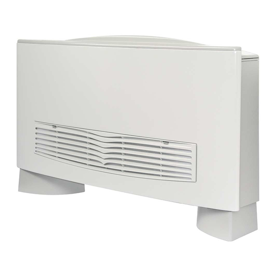
DESCRIZIONE DELL’UNITÀ UNIT DESCRIPTION Il ventilconvettore OMNIA HL (High Line) è caratterizzato The OMNIA HL (High Line) fancoil, with its characteristic dal suo design esclusivo opera dello Studio Giugiaro design by Studio Giugiaro, offers an array of technical featu- Design, ma concentra anche elevate caratteristiche tecnolo- res that make it the ideal climate-control unit for all types of giche che ne fanno il mezzo ideale di climatizzazione per applications. - Page 7 VERSIONI DISPONIBILI VERSIONS AVAILABLE I ventilconvettori della serie OMNIA HL sono disponibili in OMNIA HL fancoils are available in 4 sizes and 6 versions: 4 grandezze e 6 versioni: Grandezze: Sizes: OMNIA 10 OMNIA 10 OMNIA 15 OMNIA 15 OMNIA 25 OMNIA 25 OMNIA 35 OMNIA 35...
- Page 8 in posizione AUTO (la velocità del ventilatore è gestita dal position. (In this case fan speed is controlled by the thermostat termostato in funzione delle condizioni ambientali e dalle according to ambient temperature and DIP-switch settings.). impostazioni dei Dip Switch). CONTROLLO TERMOSTATICO CON POTENZA MODULATA: MODULATED POWER THERMOSTATIC CONTROL Caldo...
- Page 9 CONTROLLO TERMOSTATICO A 3 LIVELLI: 3 LEVEL THERMOSTATIC CONTROL Caldo Freddo Heating Cooling -3,0 -3,6 -1,5 -2,1 Ventilazione Ventilazione Fan ON Fan ON -0,3 Aletta Aletta -0,9 -0,4 Controllo termostatico a 3 livelli Banda Normale Three level normal band thermostatic control Caldo Freddo Heating...
- Page 10 La batteria può essere ruotata in cantiere. 3 FILTRO DELL’ARIA PRECARICATO ELETTROSTATICAMENTE 3 ELECTROSTATICALLY PRECHARGED AIR FILTER Filtro serie HL Aermec Aermec HL hight efficiency filter Filtro standard per ventilconvettori Standard filter for fan coil unit Diametro particelle [µm] • Particle diameters [ µ m]...
- Page 11 Resistenza al fuoco Classe 2 (UL 900). Filter fire resistance is Class 2 ( UL 900). Facilmente estraibile è fornito a corredo del ventilconvetto- The easy to remove air filter is delivered in sealed packaging re in confezione sigillata, da aprire solo al momento together with the fan coil.
- Page 12 ACCESSORI ACCESSORIES BC10 BACINELLA AUSILIARIA RACCOLTA CONDENSA BC10 AUXILIARY CONDENSATION BASIN FOR VERTI- PER VENTILCONVETTORI INSTALLATI VERTICALMENTE CALLY MOUNTED FAN COILS In materiale plastico, consente la raccolta della condensa These plastic basins collect the condensation that forms on che si forma durante il funzionamento con acqua fredda, the water connections and on the three way valve (if fitted) sulle connessioni idrauliche e sull’eventuale valvola a tre when vertically mounted units are operating in summer...
-
Page 13: Accessori • Accessories
TABELLA DI COMPATIBILITÀ DEGLI ACCESSORI • ACCESSORIES COMPATIBILITY TABLE Ventilconvettore HL • HL Fancoil Accessori Grandezza • Size Accessories Versioni • Versions ✔ ✔ ✔ ✔ HL - HL M - HL C - HL CM - HL S - HL SM ✔... -
Page 14: Dati Tecnici • Technical Data
DATI TECNICI • TECHNICAL DATA Mod. max. 2010 2910 4620 5940 ❊ Resa termica 1460 2120 3830 4870 med. Heating capacity min. 1060 1540 2890 3530 Resa termica (acqua ingresso 50°C) (E) ❊❊ 1150 1700 2750 3540 Heating capacity (water in 50°C) (E) ❊... -
Page 15: Limiti Di Funzionamento • Operating Limits
LIMITI DI FUNZIONAMENTO OPERATING LIMITS Massima temperatura ingresso acqua ......80 °C Maximum water inlet temperature......80 °C Massima pressione d’esercizio ........8 bar Maximum working pressure.........8 bar Limiti di portata: Water flow limits: MOD. Portata minima • Minimum water flow [l/h] Portata massima • Maximum water flow [l/h] 1.050 Minima temperatura media dell’acqua... -
Page 16: Potenza Frigorifera Resa • Delivered Cooling Capacity
TAV.1 POTENZA FRIGORIFERA RESA HL 10 • HL 10 DELIVERED COOLING CAPACITY Ta b.u. [°C] T w [°C] ∆ ∆ t Ta w.b. [°C] 21°C Ta b.s. 23°C Ta b.s. 25°C Ta b.s. 27°C Ta b.s. 29°C Ta b.s. 30°C Ta b.s. 1010 1117 1058... - Page 17 Ta b.u. [°C] T w [°C] ∆ ∆ t Ta w.b. [°C] 21°C Ta b.s. 23°C Ta b.s. 25°C Ta b.s. 27°C Ta b.s. 29°C Ta b.s. 30°C Ta b.s. 1123 1115 1109 1103 Le rese frigorifere della tabella sono riferite alla massima velocità. Per le altre velocità i valori devono essere moltiplicati per i seguenti fattori: Cooling capacities are referred to high speed.
- Page 18 TAV.2 POTENZA FRIGORIFERA RESA HL 15 • HL 15 DELIVERED COOLING CAPACITY Ta b.u. [°C] T w [°C] ∆ ∆ t Ta w.b. [°C] 21°C Ta b.s. 23°C Ta b.s. 25°C Ta b.s. 27°C Ta b.s. 29°C Ta b.s. 30°C Ta b.s. 1181 1058 1287...
- Page 19 Ta b.u. [°C] T w [°C] ∆ ∆ t Ta w.b. [°C] 21°C Ta b.s. 23°C Ta b.s. 25°C Ta b.s. 27°C Ta b.s. 29°C Ta b.s. 30°C Ta b.s. 1148 1077 1151 1079 1045 1031 1053 1110 1195 1080 1604 1593 1585...
- Page 20 TAV.3 POTENZA FRIGORIFERA RESA HL 25 • HL 25 DELIVERED COOLING CAPACITY Ta b.u. [°C] T w [°C] ∆ ∆ t Ta w.b. [°C] 21°C Ta b.s. 23°C Ta b.s. 25°C Ta b.s. 27°C Ta b.s. 29°C Ta b.s. 30°C Ta b.s. 1481 1162 1997...
- Page 21 Ta b.u. [°C] T w [°C] ∆ ∆ t Ta w.b. [°C] 21°C Ta b.s. 23°C Ta b.s. 25°C Ta b.s. 27°C Ta b.s. 29°C Ta b.s. 30°C Ta b.s. 1121 1029 1407 1292 1679 1542 1942 1784 1144 1034 1412 1297 1684...
- Page 22 TAV.4 POTENZA FRIGORIFERA RESA HL 35 • HL 35 DELIVERED COOLING CAPACITY Ta b.u. [°C] T w [°C] ∆ ∆ t Ta w.b. [°C] 21°C Ta b.s. 23°C Ta b.s. 25°C Ta b.s. 27°C Ta b.s. 29°C Ta b.s. 30°C Ta b.s. 2064 1446 2785...
- Page 23 Ta b.u. [°C] T w [°C] ∆ ∆ t Ta w.b. [°C] 21°C Ta b.s. 23°C Ta b.s. 25°C Ta b.s. 27°C Ta b.s. 29°C Ta b.s. 30°C Ta b.s. 1109 1563 1281 1962 1608 2341 1919 2708 2219 1222 1595 1286 1968...
-
Page 24: Potenza Termica Resa • Heating Power
TAV.5 POTENZA TERMICA RESA MODELLO HL 10 • HEATING CAPACITY HL 10 MODEL ∆ ∆ t °C (temperatura acqua entrante - temperatura aria entrante) • ∆ ∆ t °C (temperature entering water - temperature entering air) Potenza termica [W] • Heating Capacity [W] La resa termica è... - Page 25 TAV.7 POTENZA TERMICA RESA MODELLO HL 25 • HEATING CAPACITY HL 25 MODEL ∆ ∆ t °C (temperatura acqua entrante - temperatura aria entrante) • ∆ ∆ t °C (temperature entering water - temperature entering air) Potenza termica [W] • Heating Capacity [W] La resa termica è...
-
Page 26: Perdite Di Carico Batteria • Pressure Drop Coil
TAV.9 PERDITE DI CARICO BATTERIA COIL PRESSURE DROP HL 10 - 15 - 25 HL 35 Portata acqua [l/h] • Water flow [l/h] Le perdite di carico del diagramma sono relative ad una temperatura media dell’acqua di 10 °C. La tabella seguente riporta la correzione da applicare alle perdite di carico al variare della temperatura media dell’acqua. - Page 27 TAV.10 LIVELLO DI POTENZA SONORA espresso in dB SOUND POWER LEVEL rated in dB Velocità Frequenza centrale di banda (Hz) Globale Speed Band middle frequency (Hz) Global Mod. 1000 2000 4000 8000 dB (A) Max. (E) 43,6 47,1 46,4 38,5 34,4 23,9 11,1...
-
Page 28: Installazione Dell'unità • Installation
IMBALLO PACKAGING I ventilconvettori vengono spediti con imballo standard The fancoils are delivered in standard packing comprising costituito da gusci di protezione e cartone. protective shells and cardboard. INSTALLAZIONE DELL’UNITÀ INSTALLATION WARNING: check that the power supply is disconnec- ATTENZIONE: prima di effettuare qualsiasi intervento, ted before performing operations on the unit. - Page 29 COLLEGAMENTI ELETTRICI ELECTRICAL CONNECTIONS WARNING: always check that the electricity supply to ATTENZIONE: prima di effettuare qualsiasi intervento, the unit has been disconnected before carrying out any assicurarsi che l’alimentazione elettrica sia disinserita. operations. In particolare per i collegamenti elettrici si richiedono le In the specific case of electrical connections, the following verifiche relative a : must be checked:...
-
Page 30: Configurazione Dip-Switch • Dip-Switch Configuration
CONFIGURAZIONE DIP (OMNIA HL-C / HL-CM) • DIP CONFIGURATION (OMNIA HL-C / HL-CM) = Impostazioni di fabbrica • Factory settings IMPOSTAZIONI DIP-SWITCH DIPSWITCH CONFIGURATION Togliere tensione all’unità. Configuration of dipswitches must only be carried out by Da eseguire in fase di installazione solo da personale spe- qualified personnel during unit installation. -
Page 31: Autotest • Autotest Function
AUTOTEST (OMNIA HL-C / HL-CM) AUTOTEST FUNCTION (OMNIA HL-C / HL-CM) É disponibile la funzione Autotest per accertare il funzio- This function is designed to check the operation of the fan- namento del ventilconvettore. coil. La sequenza di Autotest è la seguente: To run the Autotest function, proceed as 1) Selettore (B) in posizione centrale. -
Page 32: Dati Dimensionali • Dimensions
DATI DIMENSIONALI • DIMENSIONS [mm] Mod Omnia HL 10 HL 15 HL 25 HL 35 Larghezza • 1200 Altezza • Profondità • Altezza zoccoli • Peso • Weight [kg] 13,6 14,6 17,6 20,6 Peso ventilconvettore senza zoccoli • Weight of fan coil without feet Poids ventilo-convecteur sans pieds •... - Page 33 DATI DIMENSIONALI • DIMENSIONS [mm] Mod. HL 10 HL 15 HL 25 HL 35 1200 360,5 470,5 701,5 921,5...
-
Page 34: Schemi Di Montaggio • Installation Diagrams
SCHEMI DI MONTAGGIO • INSTALLATION DIAGRAMS OMNIA HL OMNIA HL C... -
Page 35: Dati Accessori • Accessories Data
SUPPORTI PER INSTALLAZIONE PENSILE CEILING MOUNTING SUPPORTS DATI ACCESSORI • ACCESSORIES DATA ZOCCOLI PER MOBILE ZH ZH FLOOR STANDING MOUNTING FEETS... - Page 36 DATI ACCESSORI • ACCESSORIES DATA BACINELLA RACCOLTA CONDENSA BC10 DRIP TRAY BC10 BACINELLA RACCOLTA CONDENSA BC20 DRIP TRAY BC20...
- Page 37 DATI ACCESSORI • ACCESSORIES DATA VALVOLA A TRE VIE PER BATTERIA VCH THREE-WAY VALVE FOR COIL VCH Direzione del flusso Flow direction BC10 CARATTERISTICHE TECNICHE • TECHNICAL DATA Potenza iniziale assorbita • Start input powert Potenza assorbita in operazione • Operation input power Temperatura acqua •...
- Page 38 DATI ACCESSORI • ACCESSORIES DATA PANNELLO COMANDI MULTIFUNZIONE PXL2E MULTIFUNCTION CONTROL PANEL PXL2E 10.5 PANNELLO COMANDI PX 2 PANNELLO COMANDI ELETTRONICO PXB CONTROL PANEL PX 2 ELECTRONIC CONTROL PANEL PXB 10,5 10,5...
-
Page 39: Schemi Elettrici • Wiring Diagrams
SCHEMI ELETTRICI • WIRING DIAGRAMS LEGENDA • READING KEY = Interruttore generale • Main switch = Sonda temperatura acqua Water temperature sensor = Morsettiera • Terminal board = Collegamenti da eseguire in loco (1,5 mm On-site wiring (1,5 mm = Microinterruttore • Microswitch = Componenti non forniti = Motore ventilatore •... - Page 40 SCHEMI ELETTRICI • WIRING DIAGRAMS OMNIA HL OMNIA HL-S Gli schemi elettrici sono soggetti ad aggiornamento; è opportuno fare riferimento allo schema elettrico allegato all'apparecchio. Wiring diagrams may change for updating. It is therefore necessary to refer always to the wiring diagram inside the units.
- Page 41 TRASPORTO • CARRIAGE NON bagnare • Do NOT wet NON calpestare • Do NOT trample Sovrapponibilità: controllare sull’imballo la posizione della freccia per conoscere il numero di macchine impilabili Stacking: control the packing for the arrow position to know the number of machines that can be stacked NON lasciare gli imballi sciolti durante il trasporto Do NOT leave loose packages during transport...
-
Page 42: Problemi E Soluzioni • Problem And Remedy
PROBLEMI E SOLUZIONI • PROBLEM AND REMEDY PROBLEMA • PROBLEM PROBABILE CAUSA • PROBABLE CAUSE SOLUZIONE • REMEDY PROBLEME • PROBLEM CAUSE PROBABLE • MÖGLICHE URSACHE SOLUTION • ABHILFE Poca aria in uscita Errata impostazione della velocità sul pannello comandi Scegliere la velocità... -
Page 43: Servizio Assistenza Tecnica Italia
S E R V I Z I A S S I S T E N Z A VALLE D’AOSTA AOSTA AERSAT TORINO snc di Borioli Secondino & C. Strada Bertolla, 163 - 10156 Torino – – – PIEMONTE ALESSANDRIA BATTISTON GIAN LUIGI Via Liguria, 4/A - 27058 Voghera (PV) 038 362 253 ASTI - CUNEO... - Page 44 (es: i filtri d’aria). Le agenzie di Vendita Aermec ed i Servizi di Assistenza Tecnica Aermec della vostra provincia sono negli Elenchi telefonici dei capoluoghi di provincia - vedi “Aermec” - e nelle Pagine Gialle alla voce “Condizionatori d’aria - Commercio”.
Need help?
Do you have a question about the GIUGIARO Omnia HL and is the answer not in the manual?
Questions and answers