Table of Contents
Advertisement
Quick Links
User manual and parts
handbook
Verti-Drain
Model 7110
Serial number:
ATTENTION:
TO ENSURE SAFE USE OF THIS MACHINE AND TO BE ABLE
TO ACHIEVE THE BEST RESULTS, IT IS OF THE UTMOST
IMPORTANCE TO READ THIS USER MANUAL THOROUGHLY
BEFORE USING THE VERTI-DRAIN
Manual code: 911.120.473
®
Redexim
®
.
October 2005
EN
Advertisement
Table of Contents

Related Manuals for Redexim Verti-Drain 7110


Summary of Contents for Redexim Verti-Drain 7110
- Page 1 User manual and parts Redexim handbook ® Verti-Drain Model 7110 Serial number: ATTENTION: TO ENSURE SAFE USE OF THIS MACHINE AND TO BE ABLE TO ACHIEVE THE BEST RESULTS, IT IS OF THE UTMOST IMPORTANCE TO READ THIS USER MANUAL THOROUGHLY ®...
-
Page 2: Foreword
FOREWORD ® Congratulations on your purchase of the Verti-Drain . To ensure the long and safe use of ® this Verti-Drain , it is of the utmost importance for all those who will be using it to read and understand this user manual. Operation of this machine is not safe without full knowledge of the content of the manual. -
Page 3: Safety Instructions
SAFETY INSTRUCTIONS ® The design of the Verti-Drain allows for safe use. However, this is only possible if the user fully observes the safety instructions given in this manual. Read and understand the manual before (Fig. 1) starting to use the Verti-Drain. Fig. - Page 4 ® Before each use, inspect the Verti-Drain for loose bolts/nuts/parts. If present, inspect the hydraulic hoses regularly and replace them if they are damaged or show signs of wear. The replacement hoses must meet the manufacturer’s technical specifications. Always relieve the pressure from the hydraulic installation, if present, before carrying out any work on it.
- Page 5 (6) Before embarking on any job, all persons operating the ® Verti-Drain must be familiar with its functions and operating elements. ® Connect the Verti-Drain to the vehicle that will pull it exactly according to the instructions (Danger of injury!) Before driving off, make sure you have a clear view both nearby and far away.
- Page 6 (7) Location of safety stickers. (Fig. 7). Fig. 7 Used oil/grease is harmful to the environment; dispose of it according to locally applicable regulations.
-
Page 7: Table Of Contents
CONTENTS Section Description Page Foreword Guarantee conditions Registration card Safety instructions Technical data First installation, removing the machine from the pallet General parts list The power take-off shaft The length of the power take-off shaft Use of the power take-off shaft Adjusting the working depth Pin angle adjustment Driving speed... -
Page 8: Technical Data
TECHNICAL DATA Model 7110 Working width 1.0 m (40”) Working depth Up to 150 mm (6”) Tractor speed measured at 500 rpm PTO-shaft speed Hole separation 55 mm (2-1/8”) Up to 1,65 km/hr (1,03 mph) Hole separation 90 mm (3-1/2”) Up to 2,70 km/hr (1,68mph) Hole separation 125 mm (5”) Up to 3,75 km/hr (2,33mph) -
Page 9: First Installation, Removing The Machine From The Pallet
Fig. 8 FIRST INSTALLATION, REMOVING THE MACHINE FROM THE PALLET The machine is standing vertically on the pallet. To remove the pallet and lay the machine horizontally, carry out the following steps (see fig. 8): 1. Open the rear cover 2. -
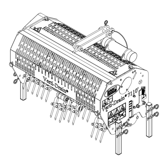
Page 10: General Parts List
9 10 Fig. 9 3.0 GENERAL PARTS LIST Figure 9 shows some important parts: Safety decal RA, read user manual before use / Toolbox with tools and manual. Safety sticker 911.280.402: keep a distance of at least 4 metres from the machine. Stop the engine before carrying out repairs or adjustments. -
Page 11: The Power Take-Off Shaft
4.0 The PTO shaft The PTO shaft is a very important part. It provides the driving force from the tractor and – if installed, used, and maintained correctly – ensures safe use of the machine. The PTO shaft has its own CE certificate. Make sure to read the PTO shaft manual. It is located on the PTO shaft itself. -
Page 12: Use Of The Power Take-Off Shaft
4.2 OPERATION OF THE PTO SHAFT To ensure correct operation of the PTO, check the following items: 1. During operation, the angle of the joints must never be greater than 30 degrees. 2. The rotating points should be aligned. 3. The overlap of the sleeves must be at least 150 mm. 4. -
Page 13: Pin Angle Adjustment
PIN ANGLE ADJUSTMENT All pins can be simultaneously adjusted with a centrally-placed handle, located on the side of the machine, see fig. 12. Lift the machine above the ground and loosen nut 2 on both sides of the machine. Adjust the angle by turning the handle. The angle can be read on the sticker. Retighten the nuts. - Page 14 Fig. 13 Fig. 14...
-
Page 15: Start Procedure
8.0 START PROCEDURE The start procedure is VERY important. If this procedure is not followed exactly as described below, serious damage may occur to the machine. The start procedure is as follows, see fig. 1. Drive to the place where you want to start. 2. -
Page 16: Transportation Of The Verti-Drain
® 10.0 TRANSPORT OF THE VERTI-DRAIN ® The user is responsible for the transport of the Verti-Drain behind the tractor when travelling on public roads. Check the national traffic regulations. On open fields, a maximum speed of 12 km/h (8 mph) should be observed, because of the weight of the Verti-Drain®. A higher speed may endanger the driver and/or other people and may even damage the machine. -
Page 17: Troubleshooting
12.0 TROUBLESHOOTING Problem Possible cause Solution Machine vibrates Crankshaft turns irregularly Machine not at 90 degrees. Angles of the PTO joints are different. Joints of PTO are not in line. Heavy conditions Adjust the operating depth. Use thinner/shorter pins. If conditions are dry, water soil. Solid/hollow pins Wrong pin Change the pin, use shorter pin. -
Page 18: Maintenance
V-belts are slipping. V-belt tension too low Adjust the V-belt tension (see section 15.3). Replace V-belts. V-belts are worn Hole distances not V-belt tension too low Adjust the V-belt tension (see equal section 15.3). Replace V-belts. V-belts are worn 13.0 MAINTENANCE Time schedule Check point/lubricating Method... -
Page 19: Eu Certificate
Use SAE 140 After every 500 operating hours. 14.0 EU DECLARATION OF CONFORMITY We, Redexim, Utrechtseweg 127, 3702 AC Zeist, The Netherlands, declare entirely on our own responsibility that the product: ® VERTI-DRAIN MODEL 7110, WITH MACHINE NUMBER AS INDICATED ON THE... -
Page 20: Technical Information
15.0 TECHNICAL INFORMATION Fig. 16 15.1 THE CRANKSHAFT The crankshaft assembly is shown in figure 16. A more detailed drawing can be found on the parts page. For a 7110, the offset between the crankshaft throws in the gearbox must be 60 degrees. 15.1.2. -
Page 21: Releasing Crankshaft Tension/Torque Values
15.1.3 Releasing crankshaft tension If parts of the crankshaft have been replaced, the crankshaft may be more difficult to turn. Pre-tension can be the cause. It is necessary to eliminate the sources of tension as follows, see fig. 16: 1. Use a hammer to tap against the centre of the throw, starting with throw 1 located next to the V-belt drive. -
Page 22: Tensioning The V-Belt Drive
15.3 TENSIONING THE V-BELT DRIVE Fig. 18 If the Verti-Drain machine does not function properly and stands still with the pins in the ground while the transmission is driven, it is possible that the V-belt pre-tension must be adjusted. This works as follows, see Fig. -
Page 23: Options, Turf Hold-Down Kit
You can use a turf hold-down kit when the turf layer comes loose. A Turf Hold Down Kit can be supplied for the 12 mm pins under number 211.710.002. The Verti-Drain 7110 is equipped standard with a pre-mounted main beam on which the turf hold-down fingers can be mounted. -
Page 24: Options, Pins
16.1 OPTIONS, PINS Pins are essential for the correct operation of the machine. There are various pins available for this machine; see the parts page for a complete overview. In general, the pins can be divided into two categories: solid and hollow pins. We advise you to use only original pins because they are completely adapted to the machine. -
Page 25: Hollow Pins
Always use pins with the same diameter and length. Replace a bent pin immediately. If this is not done, the machine can become unstable. Do not use thicker and/or longer pins than we supply. Shorter (ground off) pins can be used when shallower pricking is desired. Be aware that the operating depth indicated on the decal is only accurate when the maximum length of the pin is used. -
Page 26: Back Roller
16.3 OPTIONS, REAR ROLLER Fig. 21 The Verti-Drain is not fitted with a rear roller as standard. If desired, a rear roller can be supplied under number 211.710.004. The kit consists of a rear roller with adjustable scraper, and the fixing legs with assembly material for attachment to the Verti-Drain.
Need help?
Do you have a question about the Verti-Drain 7110 and is the answer not in the manual?
Questions and answers