
Related Manuals for Rosco 1700


Summary of Contents for Rosco 1700
-
Page 1: Operating Instructions
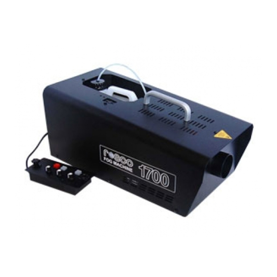
MODEL 1700 FOG MACHINE Operating Instructions Rev. date: December, 2007 Rosco Laboratories, Inc. 52 Harbor View Avenue, Stamford, CT 06902, USA (800) ROSCONY, (203) 708-8900, Fax: (203) 708-8919 email: info@rosco.com... -
Page 2: Table Of Contents
TROUBLESHOOTING GUIDE...22 PARTS LIST ... 23 INTRODUCTION This manual offers a detailed explanation of the operation of the ROSCO MODEL 1700 smoke machine. To assure efficient and safe operation, please take a few minutes to read this material. The ROSCO MODEL 1700 smoke machine is a thermal aerosol generator designed for variable fog output. -
Page 3: Important Safeguards
To do so with any high-amperage device is to assume substantial risk. Rosco strongly recommends against 5. In any facility, the smoke concentration should be controlled. The smoke should never mask emergency exits, safety signs, staircases or other safety constructions. -
Page 4: How The Machine Works
NOTE: The terms “fog” and “smoke” are used interchangeable. However the ROSCO MODEL 1700 does not produce smoke, but a mist or aerosol. -
Page 5: Timers
Turn on the main power switch (I/O) located at the rear of the machine. The remote control fits into a cavity on the rear of the machine. The Model 1700 ships with the remote control already screwed in place and can be removed. If it is not already plugged in, plug the remote control into the socket in the cavity on the back of the machine. -
Page 6: Dmx Controller
7. DAISY CHAIN (OPTIONAL) The Rosco Model 1700 has the capability to control up to 4 machines from a single controller. In this “Daisy Chain” process, the machine that controls the others is called the MASTER and the others are called SLAVES. - Page 7 DMX INTERFACE ADDRESS Binary columns LED indicating DMX signal Address Switches Address for Channel 217 Address for Channel 19 1+8+16+64+128=217 1+2+16=19 = OFF = ON Model 1700 Page 6 12/07...
-
Page 8: Do's And Don'ts
Read the entire manual before operating the machine and pay particular attention to all CAUTIONS AND WARNINGS. Use ONLY Rosco manufactured fluids. Use an extension cord which is properly rated for voltage, current and length and which is free from nicks or other signs of wear. -
Page 9: Maintenance
MAINTENANCE 1. The main fuse of the ROSCO MODEL 1700 smoke machine is located on the circuit card inside the machine. NOTE: Be sure to check the specifications when replacing any fuses. WARNING: DISCONNECT THE ROSCO MODEL 1700 FROM POWER BEFORE CHECKING OR REPLACING THE FUSE. -
Page 10: Rosco Offices
ROSCO OFFICES WORLDWIDE If the machine fails and repairs are required, call or write the nearest Rosco office (listed below) or your local Rosco dealer. UNITED STATES World Headquarters Rosco Laboratories, Inc. 52 Harbor View Avenue Stamford, CT 06902 (203) 708-8900 (800) 767-2669 E-mail: info@rosco.com... -
Page 11: Limited Warranty
During the warranty period, machines will be repaired or replaced at the option of ROSCO. The warranty does not extend to any parts of the ROSCO MODEL 1700 that have been subject to misuse or accident. Neither does the warranty cover any machine that has been opened, modified or repaired other than by ROSCO or its designated repair station. -
Page 12: Technical Specifications
Dimensions: 4 in. (10.2 cm) x 6.75 in. (17.14 cm) DUCTING HOSE Flexible, plastic hose, connects to hose adaptor for ducting of fog Dimensions: 4 in. (10.2 cm) x 25 ft. (7.62 m) Model 1700 ROSCO MODEL 1700 TECHNICAL SPECIFICATIONS REMOTE CONTROL Volume Control Sequencers... -
Page 13: Parts Identification Guide
ROSCO MODEL 1700 PARTS IDENTIFICATION GUIDE Left View with Cover Removed Mains Switch # 23711700E001 Mains Socket # 23711700E007 Model 1700 Page 12 12/07... - Page 14 ROSCO MODEL 1700 PARTS IDENTIFICATION GUIDE Right View: Main PCB and XLR A. 3 Pin male XLR-Panel Mount #23711700E009 B. 3 Pin female XLR-Panel Mount #23711700E010 C. Main PCB (240v) # 23711700E240 Main PCB (110v) # 23711700E110 Model 1700 Page 13...
- Page 15 ROSCO MODEL 1700 PARTS IDENTIFICATION GUIDE Rear View with Remote Mains Switch #23711700E001 Mains Socket # 23711700E007 Model 1700 Remote #23711700R001 Model 1700 Page 14 12/07...
- Page 16 ROSCO MODEL 1700 PARTS IDENTIFICATION GUIDE Rear View with Remote Removed A. 3 Pin male XLR-Panel Mount #23711700E009 This is where the remote plugs in Model 1700 Page 15 12/07...
- Page 17 ROSCO MODEL 1700 PARTS IDENTIFICATION GUIDE A Pump 240V # 23711700F240 Pump 110V # 23711700F110 Fluid tube to heat exchanger (part of HE assembly) Elbow 1/8 x 4mm # 23711700F001 D Rubber connecting tube # 23711700A002 Main power connection to pump. When reconnecting power to the...
- Page 18 ROSCO MODEL 1700 PARTS IDENTIFICATION GUIDE Top View: Heat Exchanger Assembly (closed) A. Hole in heat exchanger housing to access Thermal Trip Model 1700 Page 17 12/07...
- Page 19 ROSCO MODEL 1700 PARTS IDENTIFICATION GUIDE Top View: Heat Exchanger Assembly (open) A. Thermocouple attached to the heat exchanger. B. Heat Exchanger Assy. 240V # 23711700H240 Heat Exchanger Assy. 110V # 23711700H110 C. Thermal Trip # 23711700E005 D. Insulation Kit # 23711700H001...
- Page 20 ROSCO MODEL 1700 PARTS IDENTIFICATION GUIDE Male XLR Connector # 23711700E002 Remote Knob # 23711700R002 Model 1700 Remote Control Page 19 12/07...
- Page 21 ROSCO MODEL 1700 PARTS IDENTIFICATION GUIDE Main PCB (240v) # 23711700E240 Main PCB (110v) # 23711700E110 Heatsink # 23711700A001 Model 1700 Main PCB with Heatsink Page 20 12/07...
- Page 22 ROSCO MODEL 1700 PARTS IDENTIFICATION GUIDE A. Calibration potentiometer for TEMPERATURE CONTROL B. Calibration potentiometer for PUMP SPEED SETTING C. Fuse 6.3 amp (240v) #23711700E003 Fuse 12.5 amp (115v) #23711700E004 D. Positive terminal for the thermocouple. E. Negative terminal for the thermocouple.
-
Page 23: Troubleshooting Guide
ROSCO MODEL 1700 TROUBLESHOOTING GUIDE SYMPTOM Machine does not fog when READY light is on and fog button is pressed Machine pumps but has no output (No smoke) Machine pumps but has low output (Reduced output) Fog is wet and leaves a... -
Page 24: Parts List
Model 1700 Mains Socket 23711700E008 Model 1700 Mains Cable 23711700E002 Model 1700 Male XLR Connector 23711700E009 Model 1700 3 Pin male XLR PM 23711700E010 Model 1700 3 Pin female XLR PM 23711700E003 Model 1700 Fuse 6.3A (240v) 23711700E004 Model 1700 Fuse 12.5A (115v)
Need help?
Do you have a question about the 1700 and is the answer not in the manual?
Questions and answers