
Related Manuals for AMS AS621 Series


Summary of Contents for AMS AS621 Series
- Page 1 User Guide UG000452 AS621x Eval Kit AS6212-EK, AS6214-EK & AS6218-EK v1-01 • 2019-Oct-08...
-
Page 2: Table Of Contents
Document Feedback AS621x Content Guide Content Guide Introduction ........3 Temperature Register ........9 Schematics, Layers and BOM ..11 Kit Content ............ 3 Ordering Information ........3 Schematics ..........11 Getting Started ....... 4 Layout and Board Dimensions....11 Bill of Materials ........... -
Page 3: Introduction
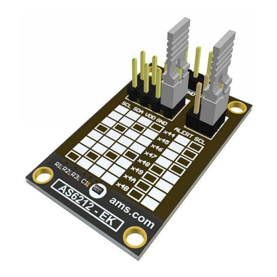
Document Feedback AS621x Introduction Introduction The AS621x Eval Kit is a small PCB allowing a simple and quick evaluation of the AS621x digital temperature sensors without the need to design a custom PCB. This small form factor board is fully assembled with the AS621x temperature sensor and its necessary external components. -
Page 4: Getting Started
Document Feedback AS621x Getting Started Getting Started The AS621x Eval Kit is ideal for rapid setup of a digital temperature sensor. To get started connect the board to your microcontroller as described in Figure 4. Add a command in your source code to request two bytes from the selected I²C address. -
Page 5: Hardware Description
Document Feedback AS621x Hardware Description Hardware Description The P1 connector does provide all relevant signals, which can be easily wired to a microcontroller and to the power supply. Figure 4: Eval Kit Pin-Out Symbol Description Info I²C clock Use R1 if pull-up is required I²C data Use R2 if pull-up is required Ground... -
Page 6: As621X Configuration
Document Feedback AS621x Hardware Description AS621x Configuration With the address selector, it is possible to choose the I²C address of the device. The included jumpers are an easy way of setting the I²C address of the sensor. Both address selectors must not be left open. -
Page 7: Power Supply And Connections
Document Feedback AS621x Hardware Description Power Supply and Connections The PCB has to be connected to an external microcontroller. P1 is populated with a 1x5 pin header and is required for power supply as well as I²C communication. In addition to that, it can be used to monitor the interrupt status via pin 5 (IRQ). -
Page 8: Software Description
Document Feedback AS621x Software Description Software Description The AS621x has 4 data registers. With the use of the index register, it is possible to address the specific data register. When powered up the address register is set to 0x0. Figure 8: Data Registers For additional configuration settings, the Config register (0x1) has to be addressed. -
Page 9: Temperature Register
Document Feedback AS621x Software Description Figure 10: Index Register Value Address Bits Temperature Register Figure 11: Temperature Register MSB Byte LSB Byte The temperature register contains the digitally converted temperature value. It consists of 2 bytes and can be converted according to the following formula: Positive values= |Value| / LSB Negative values= Complement( |Value| / LSB ) + 1 Example +75°C... - Page 10 Document Feedback AS621x Software Description Figure 12 Temperature Conversion Examples Temperature (°C) Digital Output (Binary) Digital Output (Hex) 100.0 0011 0010 0000 0000 3200 75.0 0010 0101 1000 0000 2580 50.0 0001 1001 0000 0000 1900 25.0 0000 1100 1000 0000 0C80 0.125 0000 0000 0001 0000...
-
Page 11: Schematics, Layers And Bom
Document Feedback AS621x Schematics, Layers and BOM Schematics, Layers and BOM The schematics, layout and BOM of the adapter board are shown below for reference. Schematics The schematics of the board is shown below in Figure 13: Figure 13: Schematics Layout and Board Dimensions. - Page 12 Document Feedback AS621x Schematics, Layers and BOM Figure 14: Figure 15: Top Layer Bottom Layer The board dimensions are shown below in Figure 16 Figure 16: Dimensions Eval Kit Manual • PUBLIC UG000452 • v1-01 • 2019-Oct-08 │ 12...
-
Page 13: Bill Of Materials
Document Feedback AS621x Schematics, Layers and BOM Bill of Materials The BOM of the Board is shown below in Figure 17 Figure 17: Position Name Value Header 2X2 Header 4X2 Header 1X5 10nF AS621x AS621x-WLCSP6 Eval Kit Manual • PUBLIC UG000452 •... -
Page 14: Revision Information
Document Feedback AS621x Revision Information Revision Information Changes from previous version to current revision v1-01 Page Initial version ● Page and figure numbers for the previous version may differ from page and figure numbers in the current revision. ● Correction of typographical errors is not explicitly mentioned. Eval Kit Manual •... -
Page 15: Legal Information
AG shall not be liable to recipient or any third party for any damages, including but not limited to personal injury, property damage, loss of profits, loss of use, interruption of business or indirect, special, incidental or consequential damages, of any kind, in connection with or arising out of the furnishing, performance or use of the technical data herein.
Need help?
Do you have a question about the AS621 Series and is the answer not in the manual?
Questions and answers