
Related Manuals for WIKA mensor 9250


Summary of Contents for WIKA mensor 9250
- Page 1 Operating Instructions Transducer Display Model 9250 Transducer Display Model 9250 PN 0018908001P• 09/2022...
- Page 2 Transducer Display Model 9250 This Warning symbol indicates that danger of injury for persons and the environment and/or considerable damage (mortal danger, danger of injury) will occur if the respective safety precautions are not taken. Warning This Caution symbol indicates danger for the system and material if the respective safety precautions are not taken.
-
Page 3: Table Of Contents
Transducer Display Model 9250 Table of Contents 1. General Information 1.1 Warranty 1.2 Important Notice 1.3 Trademarks and Copyrights 1.4 Software License Agreement 1.5 Mensor Service Plus 1.5.1 After the Warranty 1.5.2 Calibration Services 1.5.3 Certifications and Accreditations 1.6 Packaging for Shipment 2. - Page 4 Transducer Display Model 9250 5.1.1 Setup Applications 5.1.2 Display Screen Features 5.2 Initial Setup 5.2.1 Contact and Version Information Application 5.2.2 Language Selection 5.3 Application Selection and parameter inputs 5.4 Applications: 5.4.1 Measure Application 5.4.1.1 Auxiliary Displays 5.4.1.2 Zero Button 5.4.1.3 Tare Button 5.4.2 Settings Application...
- Page 5 Transducer Display Model 9250 5.4.9 Service Application 5.4.10 Unlocked Service Application 6. Remote Operation 6.1 Command Set 6.2 Ethernet 6.3 Serial 6.3.1 Serial Cable Requirements 6.4 Mensor Command Set 6.5 Command and Query Format 6.6 Command Set Definitions 6.7 Output Formats 6.8 Model 9250 Commands and Queries 6.8.1 Units Command Syntax for Measurement Units 6.8.2 Model 9250 Error Codes...
- Page 6 Transducer Display Model 9250 8. Maintenance 8.1 Beyond the Warranty 9. Calibration Service Application 9.1.1 Service Application (unlocked) Calibration Data One Point Cal Application Two Point Cal Application Linearization Head Pressure 10. Appendix 10.1 Conversion Factors, PSI 10.2 Conversion Factors, Millitorr 10.3 Conversion Factors, Pascal Operating Instructions - Model 9250...
-
Page 7: General Information
Mensor has made a concerted effort to provide complete and current information for the proper use of the equipment. If there are questions regarding this manual or the proper use of the equipment, contact Mensor at: Mensor WIKA Alexander Wiegand SE & Co. KG 201 Barnes Drive Alexander-Wiegand-Straße 30 San Marcos, Tx 78666 D-63911 Klingenberg / Germany Tel: 1.512.396.4200... -
Page 8: Trademarks And Copyrights
Strictly observe the following when shipping the instrument: All instruments delivered to WIKA or Mensor must be free from any kind of hazardous substances (acids, bases, solutions, etc.) and must be cleaned before being returned. - Page 9 Transducer Display Model 9250 WARNING! Physical injuries and damage to property and the environment through residual media Residual media in the dismounted instrument can result in a risk to persons, the environment and equipment. ▶ With hazardous substances, include the material safety data sheet for the corresponding medium. When returning the instrument, use the original packaging or a suitable transport packaging.
-
Page 10: Safety Notices
Transducer Display Model 9250 Safety Notices User Responsibilities To ensure safety, the user must make sure that: • The system is used properly, no dangerous media are used and that all technical specifications are observed. • The system is operated in perfect operating condition. •... -
Page 11: Warnings And Caution Notices
Transducer Display Model 9250 Warnings and Caution Notices WARNING: HIGH PRESSURE! High pressure gases are potentially hazardous. Energy stored in these gases and liquids can be released suddenly and with extreme force. High pressure systems should be assembled and operated only by personnel who have been trained in proper safety practices. -
Page 12: General Description
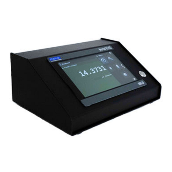
Transducer Display Model 9250 General Description The Model 9250 Transducer Display is a multi-channel remote pressure indicator designed to test and calibrate a variety of pressure devices in either absolute or gauge pressure modes. The Model 9250 can have up to three external transducers. Figure 3.1 - Desktop version Features Here is a short list of significant features designed into the Model 9250:... -
Page 13: Turning On
Transducer Display Model 9250 Turning On You can confirm that your Model 9250 is operational right now. Apply power to the power connector on the rear of the instrument with the included power adapter, and press the power switch to ON. The system will go through an initialization process, which takes about 45 seconds, and then a display will appear similar to the screen shown below. -
Page 14: Display
Transducer Display Model 9250 Display The display is made up of two sections. In the main screen (“Measure Application”), the left two thirds show the transducer channels that are configured for display, along with the pressure reading, units, mode (absolute or gauge), channel label, an auto zero or tare button (if enabled) and any auxiliary indications that have been chosen. -
Page 15: Installation
Transducer Display Model 9250 Installation Unpacking the Instrument In addition to functional testing, each unit is inspected for appearance prior to leaving the factory. Upon receipt, please examine the instrument for shipping damage. Report any apparent damage to the carrier immediately. In addition to this manual, you should have: •... -
Page 16: Dimensions (Inches)
Transducer Display Model 9250 Dimensions (Inches) Operating Instructions - Model 9250... -
Page 17: Rear Panel
Remote Communication Connections See Section 7, Remote Operation, for connections and commands for operation over Ethernet, or RS-232 ports. Power Up Apply power to the power connector on the rear of the instrument using the power adaptor included, and switch the power switch on the front of the unit ON. The instrument will go through an initialization process and system check. -
Page 18: Electrical Block Diagram
Transducer Display Model 9250 Electrical Block Diagram Figure 4.6 - Electrical Block Diagram Operating Instructions - Model 9250... -
Page 19: Local Operation And Setup
Transducer Display Model 9250 Local Operation and Setup General Operation This section describes the procedures for operating the Model 9250 from the front panel. Instructions for operating the device remotely from an external computer are covered in Section 6, Remote Operation. By following the procedures provided in these two sections and Section 9, Calibration, you can expect your Model 9250 to be dependable for many years of useful service. - Page 20 Transducer Display Model 9250 Initial Setup Sections 5.2.1 and 5.2.2 are provided first so that the operator can initially check the information screen to verify the installed components and to change the language if needed. 5.2.1 Contact and Version Information Application Press this application button to display Mensor contact, installed sensor, instrument, and software version information.
- Page 21 Transducer Display Model 9250 Application Selection and parameter inputs The application selection area on the right one third of the screen (see Figure 5.1.2 - Display Screen Fea- tures) is the area where setup, information and calibration Apps can be chosen. A second and third page of application selections can be accessed by pressing the page down button [ ].
- Page 22 Transducer Display Model 9250 Applications: 5.4.1 Measure Application The Measure App is the normal operation screen referred to in previous instruments as the ‘main screen’. This application is different from the others in that it is not used to set up the configuration but is used to monitor the pressure applied to the external transducers.
- Page 23 Transducer Display Model 9250 5.4.1.1 Auxiliary Displays The screen in figure 5.4.1.1 shows all of the possible auxiliary display items that can be included in the Measure App, in addition, each channel can contain one of two possible calibration functions. The auxiliary display item includes “Alternate Units”, “Peak”...
- Page 24 Transducer Display Model 9250 5.4.1.2 Zero Button If the Zero Calibration function has been chosen in the Transducer App (section 5.4.4), then the Zero Cal Button [ ] will appear in the Measure App. If the channel is measuring absolute pressure, and the Zero Cal Button is pressed, a keyboard will appear to allow a single point calibration.
- Page 25 Transducer Display Model 9250 5.4.1.3 Tare Button If the Tare calibration function has been chosen in the Transducer App (section 5.4.4), then the Tare But¬ton [ ] will appear on the channel screen. The Tare button and the Zero Button cannot appear on the screen at the same time, in the same channel.
- Page 26 Transducer Display Model 9250 5.4.2 Settings Application The Settings App is used to set up general settings for the display. Settings parameters include Language, Brightness, Volume, User 1 base units, User 1 multiplier, User 2 base units, User 2 multiplier, Barometer units, and Configuration. Figure 5.4.2 shows these parameters as indicated when the Settings App has been chosen.
- Page 27 Transducer Display Model 9250 5.4.2.2 Brightness The Brightness setting provides a sliding scale to increment the screen brightness on all screens. Sliding your finger along the bar graph or touching anywhere in the bar graph will change the brightness of the screen. After the setting is made and your finger is removed from the screen, the menu will revert to the basic settings menu.
- Page 28 Transducer Display Model 9250 5.4.2.4 User base units / Base units multiplier When choosing a unit of measure from the Measure Application (main screen), standard units can be chosen in addition to two user defined units. User units 1 and 2 are defined in the Settings App using “User 1 base units”, “User 1 multiplier”...
- Page 29 Transducer Display Model 9250 5.4.3.1 Frame Format The Frame format button sets the display in the Measure Application to Single Frame, Dual Frame, or Triple Frame. Figure 5.4.3.1 shows the available selections for the Frame Format parameter. Figure 5.4.3.1 - Frame Format 5.4.3.2 Frames Channel The channel setting in the Frames application provides a way to choose which channel(s) appears and in what order within the Measure Application (Main Screen).
- Page 30 Transducer Display Model 9250 In Figure 5.4.3.2-A, the Channels have been set in order for each frame format and the frame format has been set to “Frame triple”. In the Measure App, the resulting channel position will be Channel “A’ on top, Channel “B”...
- Page 31 Transducer Display Model 9250 5.4.4.1 Transducer Channel Selection To set the transducer parameters, the transducer channel must be selected. Transducer parameters are identical for all channels but can be set differently in each channel. Figure 5.4.4.1 shows two displays where channels “A” and “B” have been selected. Figure 5.4.4.1 - Transducer Channel Selection 5.4.4.2 Transducer Delta Emulation If there is more than one transducer installed, the Delta Channel option will appear as a selection in the...
- Page 32 Transducer Display Model 9250 5.4.4.3 Transducer Filter The Filter is an electronic filter to smooth out the pressure readings. Because of differences in resolution, greater filtering may display a more stable reading for some pressure units. Turn off the Filter by selecting “Off”, and select varying degrees of filtering for the current units by selecting “Low”, “Normal”...
- Page 33 Transducer Display Model 9250 5.4.4.5 Auxiliary Displays The Transducer Channel Auxiliary Display(s) can be set in the Transducer App by selecting Auxiliary Dis¬play 1, 2, or 3 and selecting from, None, Peak, Rate, or Units. Figure 5.4.4.5-A shows auxiliary displays 1, 2, and 3 set for units, peak, and rate respectively. Auxiliary displays will appear in the Measure App as seen in Figure 5.4.4.5-B.
- Page 34 Transducer Display Model 9250 5.4.4.6 Cal Function The Transducer Cal Function presents a choice of None, Tare, or Zero. Choosing Zero will enable the Zero Cal Button [ ] in the Measure App. Choosing Tare will enable the Tare Button [ ] in the Measure App.
- Page 35 Model 9250 5.4.5.1 Remote Command Set The remote command set parameter provides a choice of the Mensor command set or the WIKA SCPI command set. Both sets of commands are listed in Section 6, Remote Operation. Figure 5.4.5.1 - Remote Command Set 5.4.5.2 Remote Communication Settings...
- Page 36 Transducer Display Model 9250 Radio button selection Setting the Ethernet DHCP to yes will have a short delay while the DHCP server is contacted. If a DHCP server is not found, an error will be indicated. If DHCP is enabled, the IP address, Netmask and Gateway are greyed out and locked, these are controlled by the DHCP server.
- Page 37 Transducer Display Model 9250 5.4.7 Leak Test Application The Leak Test application provides a way to check the system for leaks into or out of the system. This App is found on the second page of the Apps menu accessed by pressing the page down button [ The operator defines a leak by setting the Time parameter and the Delta parameter.
- Page 38 Transducer Display Model 9250 5.4.8 Troubleshooting Application TheTroubleshoot Application will display information about error conditions and remote communications. Within the troubleshooting screen (Figure 5.4.8-B), push the Error button to display any errors that have occurred in the instrument due to a communication or network error.
- Page 39 Transducer Display Model 9250 5.4.9 Service Application The service application is a password protected area where calibration of all connected sensors can be accomplished. In addition, this is where the password for entering this area can be changed. Figure 5.4.9-A - Service Application (locked) Press the Enter button to show the numeric keypad to enter a password.
- Page 40 Transducer Display Model 9250 5.4.10 Unlocked Service Application After the Password has been entered, the unlocked Service Application will appear (Figure 5.4.11). To re-lock this screen, press the lock button. Figure 5.4.11 - Unlocked Service Application From the Unlocked Service Application, the Password can be changed by pressing the Enter button next to the Change Password label.
- Page 41 Selections may include the following or may be added per customers’ specifications: • Mensor (default) • SCPI WIKA (The SCPI WIKA mode emulates the WIKA command set in SCPI format.) Ethernet The Ethernet function allows the user to set the following by inputting a numeric value in each separate field: •...
- Page 42 Transducer Display Model 9250 Serial Set the Serial communication parameters as shown in Section 5.4.5 Remote Application. The serial communication port allows the Model 9250 to communicate in RS-232 format with computers, terminals, PDAs, or similar hosts. These parameters should be set to match your host computer. Default settings are: 57600 baud, 8 data bits, 1 stop bit, no parity, and no echo.
- Page 43 Transducer Display Model 9250 Mensor Command Set This Mensor command set is the default on the Model 9250. For queries (ending with a?), the Data column represents the response of the Model 9250. All response strings begin with a space character or an “E”...
- Page 44 Transducer Display Model 9250 When a valid query is received, the Model 9250 will return { data } terminated by CR and LF. Floating point data is returned in the current engineering units in exponential format. Output Formats Pressure readings are returned in exponential notation in a format according to the OUTFORM command as follows.
- Page 45 Transducer Display Model 9250 ActualPress? <n>, <f> <sp>n.nnnnnE+nn<cr><lf> Returns the linearity actual pressure for segment n, where n is 0 to 10 Address 1-31 Sets the GPIB Address Address? <sp>nn<cr><lf> Returns the GPIB Address Asset_tag 16 char string General purpose string for customer use.
- Page 46 Transducer Display Model 9250 Chanfunc n, func<cr><lf> Sets the auxiliary display function where “n” is the auxiliary display to be set (1,2, or 3) and “func” is the function (none, peak, rate, units) Chanfunc? <n> <sp>CCCCC…<cr><lf> Returns the auxiliary display function specified by “n”...
- Page 47 Transducer Display Model 9250 Gastemp? <sp>+n.nnnnnE+nn<cr><lf> Gets the head pressure gas tempera- ture. Degrees in ∞F or ∞C depend- ing on selected units category. See HEADUNITS?Only set for currently active channel. See alias command MEDIATEMP? Gateway nnn.nnn.nnn.nnn Sets the Ethernet gateway address Gateway? <sp>nnn.nnn.nnn.nnn<cr><lf>...
- Page 48 Transducer Display Model 9250 LANGUAGE XXXX Set the displayed language. String to be sent may be ENGLISH, ENG- LISH GB, ENGLISH CA, GERMAN, FRENCH, FRENCH CH, FRENCH CA, SPANISH, SPANISH LA, ITALIAN, POLISH, PORTUGUESE, PORTU- GUESE BR, RUSSIAN, JAPANESE, CHINESE, KOREAN LANGUAGE? <sp>XXXX<cr><lf>...
- Page 49 Transducer Display Model 9250 Loudness Integer 0 to 100 Set the speaker volume to ON or OFF. Greater than 50 sets on, less than or equal to 50 turns off Loudness? <sp>NNN<cr> Returns the speaker volume, between 0 and 100 <lf>...
- Page 50 Transducer Display Model 9250 RangeMax? <sp>n.nnnnnE+nn<cr><lf> Returns the maximum range of the ac- tive transducer in the current units RangeMin? <sp>n.nnnnnE+nn<cr><lf> Returns the minimum range of the ac- tive transducer in the current units Rate? <sp>n.nnnnnE+nn<cr><lf> Returns the rate reading of the instru- ment in current units/current time unit (see: Runits) Rdecpt?
- Page 51 Transducer Display Model 9250 Sstop? <sp>X<cr><lf> Returns the serial stop bits SUBUNITS? <sp>XXXX<cr><lf> Returns the instrument auxiliary dis- play units in a text string Tare ON / OFF Tares the reading to zero Tare? <sp> n.nnnnnE+nn <cr><lf> Returns value of Tare Transfer_factory_to_lin- Copy factory linearity coefficients to earity...
- Page 52 Transducer Display Model 9250 6.8.1 Units Command Syntax for Measurement Units Description Output Format Type pounds per square inch Imperial inches of mercury @ 0°C INHG Imperial inches of mercury @ 60°F INHG Imperial inches of water @ 4°C INH2O Imperial inches of water @ 20°C INH2O...
- Page 53 Transducer Display Model 9250 6.8.2 Model 9250 Error Codes Code Serial Poll Byte Description Error String Returned No errors NO ERRORS Parameter error EGPIB PARAMETER ERROR: String that was sent Syntax error EGPIB SYNTAX ERROR: String that was sent 6.8.3 SCPI Commands and Queries OUTPut :CHANnel Set the active channel to A, B, C, or D...
- Page 54 Transducer Display Model 9250 :VALue? Returns the units conversion factor :REFerence [:HEIGht] <n> Sets the head pressure height in cm :HEIGht? Returns the head pressure height in cm :MODE? Returns “OFF”, “GAS”, or “LIQUID” :MODE OFF | GAS | LIQUID Sets the head pressure mode :MEDium<n>...
- Page 55 Transducer Display Model 9250 :INDEX? Returns the index number. index unit 0 bar 1 mbar 2 Pa 3 psi 4 atm 5 kp/cm2 6 lbf/ft2 7 kPa 8 cmH2O(4°C) 9 inH2O(4°C) 10 inH2O(60°F) 11 ftH2O(4°C) 12 µmHg(0°C) 13 mmHg(0°C) 14 cmHg(4°C) 15 inHg(0°C) 16 inHg(60°F) 17 - -...
- Page 56 Transducer Display Model 9250 7 Options Delta Channel The Delta Channel is a virtual channel that can display an arithmetic combination of the value of any two transducers that are connected. The Delta Channel is active when there is more than one transducer attached.
- Page 57 Transducer Display Model 9250 Maintenance The Model 9250 was designed for maintenance-free operation. User maintenance is not recommended. If you have questions not covered by this manual, call 1.800.984.4200 (USA only), or 1.512.396.4200 for assistance, or send an e-mail to tech.support@mensor.com. Beyond the Warranty Take advantage of Mensor’s expert product care.
- Page 58 Transducer Display Model 9250 Figure 9.1-B - Service Application (Enter Password) Note: The default Password is 123456. After entering this for the first time, the password can be changed. 9.1.1 Service Application (unlocked) After the Password has been entered, the unlocked Service Application will appear (Figure 9.1.1).
- Page 59 Transducer Display Model 9250 9.2 Calibration Data The Calibration Data Application is where the calibration data for each transducer is stored and amended. The Serial number (S/N), Zero offset (Zero) and Span offset (Span) can be seen in this screen. The date of calibration, the calibration interval and the certificate number can be entered by pressing the corresponding button, then saved by pressing the Check [ ] button.
- Page 60 Transducer Display Model 9250 Two Point Cal Application The Two Point Cal Application provides a place to adjust the Transducer Zero and Span (some- times referred to as the offset and slope). Figure 9.4 - Two Point Cal Application Follow the steps below for a complete 2 Point Calibration: Select a Transducer to calibrate by pressing the Channel button at the top of the screen.
- Page 61 Transducer Display Model 9250 When the “High Reading” or “Low Reading” is selected, the main reading will become a button. When pressed the current reading will be used as a value. After all four values (High Reference, High Reading, Low reference, & Low reading) have been entered, the Adjust button will become active.
- Page 62 Transducer Display Model 9250 Figure 9.5-B - Linearization Values Figure 9.5-B shows some typical values that might be seen in a linearization calibration. In the bottom right hand corner of this screen is the Graph Icon [ ] that, when pressed, reveals a Linearization Error Graph (figure 9.5-C) that gives a visual representation of the errors associated with the values entered in the Linearization screen.
- Page 63 Transducer Display Model 9250 Relative Scale Figure 9.5-C - Linearization Error Graph When satisfied that all values have been entered correctly, press the adjust button and then the save button to save the new calibration data in the transducer memory. Note: After calibration is complete, return to the Calibration Data Application (Section 9.6) to record the certificate number, calibration interval, and the date of calibration.
- Page 64 Transducer Display Model 9250 The Head Pressure should not be active when calibrating the Model 9250 transducers. The Head Height should be set at zero before calibrating the transducers of the Model 9250. Difference in height between the laboratory Notice standard and the Model 9250 transducer during the calibration should be factored into the uncertainty analysis.
- Page 65 Transducer Display Model 9250 Figure 9.6-C Pressure values (Channel A) Figure 9.6-D shows the Head Pressure hydraulic screen. The height, media density, media tempera ture and local gravity can be entered here based on the specific setup of the system Figure 9.6-D - Head Pressure, Hydraulic Operating Instructions - Model 9250...
- Page 66 Transducer Display Model 9250 10 Appendix Table 10.1 - Measurement Units (unitno) Code Description Output Format pounds per square inch inches of mercury @ 0°C inHg 0°C inches of mercury @ 60°F inHg 60°F inches of water @ 4°C inH2O 4°C inches of water @ 20°C inH2O 20°C inches of water @ 60°F...
- Page 67 Transducer Display Model 9250 10.1 Conversion Factors, PSI The values listed in the column “To convert from PSI” are the values imbedded in the instrument program. The values listed under “To convert to PSI” are internally calculated approximations based on the imbed- ded values.
- Page 68 Transducer Display Model 9250 10.2 Conversion Factors, Millitorr The following table lists factors which should be used as multipliers when converting other pressure units to or from millitorr. Table 10.3 - Conversion Factors, millitorr Code Pressure Unit To convert from millitorr To convert to millitorr 0.00001933672 51715.08...
- Page 69 Transducer Display Model 9250 10.3 Conversion Factors, Pascal The following table lists factors which should be used as multipliers when converting other pressure units to or from Pascal. 10.4 - Conversion Factors, Pascal Unit No. Pressure Unit To convert from Pascal To convert to Pascal 1.450377E-04 6.894757E+03...
- Page 70 Tel: 512-396-4200 Website: www.mensor.com Fax: 512-396-1820 Email: sales@mensor.com PN 0018908001P • 09/2022 Transducer Display Model 9250 WIKA Alexander Wiegand SE & Co. KG Alexander-Wiegand-Straße 30 D-63911 Klingenberg / Germany Tel: (+49) 93 72/132-5015 Website: www.wika.de Fax: (+49) 93 72/132-8767 Email: CTsales@wika.de...
Need help?
Do you have a question about the mensor 9250 and is the answer not in the manual?
Questions and answers