
Related Manuals for WIKA mensor 9476


Summary of Contents for WIKA mensor 9476
- Page 1 Operating instructions Pressure verification system Model 9476 Pressure verification system Model 9476...
- Page 2 Operating instructions model 9476 © 05/2019, Mensor, LP. All rights reserved. Mensor is a registered trademark of Mensor, LP. All other brand and product names are trademarks or registered trademarks of their respective companies. Prior to starting any work, read the operating instructions! Keep for later use! Mensor operating instructions Pressure verification system, Model 9476...
-
Page 3: Table Of Contents
Contents 1. General Information Further information: ....... . . 5 Warranty . - Page 4 Beyond the Warranty ......28 Calibration Services by Mensor or WIKA worldwide ..... 29 6.
-
Page 5: General Information
- Application consultant: Tel.: (+1) 512-396-4200 (+1) 800-984-4200 (USA only) Fax: (+1) 512-396-1820 E-Mail: sales@mensor.com techservices@mensor.com Importer for Europe WIKA Alexander Wiengand SE & Co. KG Alexander Wiegand-Straße Address 63911 Klingenberg, Germany - Internet address: www.wika.de / www.wika.com - Relevant data sheet: CT 25.12... -
Page 6: Fcc Emission Notice
General Information from the date of shipment. No other express warranty is given, and no affirmation of Seller, by words or actions, shall constitute a warranty. SELLER DISCLAIMS ANY IMPLIED WARRANTIES OF MERCHANTABILITY OR FITNESS FOR ANY PARTICULAR PURPOSES WHATSOEVER. If any defect in workmanship or material should develop under conditions of normal use and service within the warranty period, repairs will be made at no charge to the original purchaser, upon delivery of the product(s) to the factory, shipping charges prepaid. -
Page 7: Safety
Safety 2. Safety Explanation of Symbols DANGER! ... indicates a directly dangerous situation resulting in serious injury or death, if not avoided. WARNING! ... indicates a potentially dangerous situation that can result in serious injury or death, if not avoided. CAUTION! ... - Page 8 Safety Skilled personnel Skilled personnel, authorized by the operator, are understood to be personnel who, based on their technical training, knowledge of measurement and control technology and on their experience and knowledge of country-specific regulations, current standards and directives, are capable of carrying out the work described and independently recognizing potential hazards. Operating personnel The personnel trained by the operator are understood to be personnel who, based on their education, knowledge and experience, are capable of carrying out the work described and independently recognizing potential hazards.
-
Page 9: Personal Protective Equipment
Safety Personal Protective Equipment The personal protective equipment is designed to protect the skilled personnel from hazards that could impair their safety or health during work. When carrying out the various tasks on and with the instrument, the skilled personnel must wear personal protective equipment. - Page 10 Safety inside the 9476 chassis. WARNING! Any maintenance or troubleshooting should be performed by technicians knowledgeable in pneumatic pressure instrumentation and AC powered electronic equipment. WARNING! The unit weighs approximately 40 lbs. and is intended as a ‘two person lift.’ HOT! Some moving mechanical devices contained within the chassis (specifically solenoid valves) can build up excessive heat during continuous operation.
-
Page 11: Initial Setup
Initial setup 3. Initial setup Unpacking and initial setup The initial installation should include removing any packing material used in shipment and inspect that fittings and screws are snug, and that hoses and electrical cords are not chaffed or cut. The Model 9476 should be installed on a level surface (bench top or rack) with adequate airflow to keep the system within its 15 to 45 C optimum operating temperature range. -
Page 12: Operation
Front panel operation Operation Generally, once configured, the system requires power, clean dry pressure media, and possibly a vacuum source for sub-atmospheric control and near-atmospheric control. Start up operation commences when power is applied using the rear panel power switch. ■... -
Page 13: Panel Operation
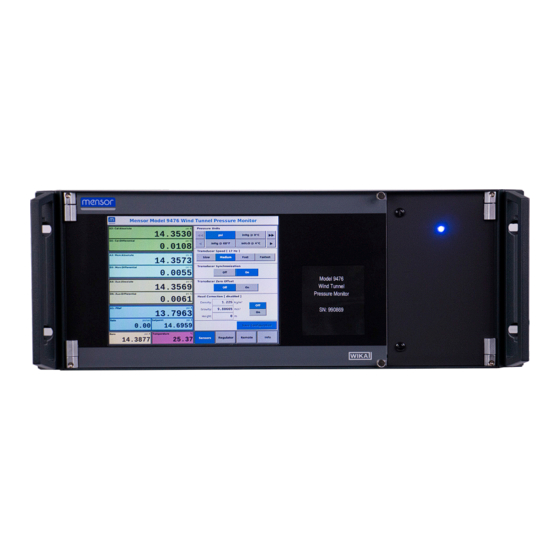
Installation 4. Panel operation Panel overview 4.1.1 Front panel The front panel contains a color LCD monitor with touch screen along with a blue power LED indicator. Manual operation of the 9476 is through the front panel using the touch screen interface. The features provided on the touch screen are listed in the general operations section. -
Page 14: Front Panel Operation
Front Panel Operation The unit powers up into the default operating screen in the default mode of measure and with the control set point equal to the first barometric reading measured. The screen is divided into 2 primary sections, each with various sub-sections and a fixed model header across the top of the screen. -
Page 15: Regulator Configuration And Control
Pressure units are set by tapping the button of the desired unit. Use the buttons with left and right pointing arrows to scroll ■ through the list of available pressure units. The buttons with single arrows scroll a single page at a time. The buttons with double arrows jump to the first or last page of units. -
Page 16: Remote Configuration And Control
transducers installed, current solenoid routing, and current barometric pressure. The min/max values will be based on the smallest range transducer channel currently installed and routed to the PREF channel. The ranges of the absolute transducer channels are also limited by the corresponding differential range. Vent mode is used to release the control channel pressure to atmosphere through the vent port on the rear panel. -
Page 17: System Info
4.4.4 System Info The Info category displays system details including model number, instrument software version, serial number and details about each transducer installed in the unit. Each transducer info panel displays the model, firmware version, serial number, date of calibration, pressure range, and native pressure units. The dual transducer panels will display two ranges for absolute and gauge designated by an “A”... -
Page 18: Serial Communication Configuration
▶ Remote communication uses case-insensitive ASCII commands and queries. ▶ Communication is identical regardless of connection method used (e.g.: serial or ethernet). ▶ All commands and queries sent to the 9476 should be terminated with a carriage return (0x0D) and line feed (0x0A) pair. All responses are terminated with a carriage return and line feed pair. - Page 19 STATUS? RDGS? Example Meta-Queries: ■ XSPD# HCGRAVITY+ AUXCONN$ A single asterisk (*) followed by CRLF can be sent to the unit to get a comma separated list of all valid remote commands. Each command name will have a suffix of all the query characters supported by that message. If the message refers to a saved configuration value there will also be a caret (^) symbol in the suffix list.
- Page 20 HIDEAUX get or set a boolean value to hide AUX readings from the HIDEAUX? True or False ?=#$ RDGS and ALLRDGS queries. The AUX transducer is HIDEAUX=0 (when queried) optional in the system. When not installed there will be NaN HIDEAUX=1 placeholders in the responses from the RDGS and ALLRDGS HIDEAUX=True...
- Page 21 HCHEIGHT get or set the head pressure correction height difference in meters. Use positive HCHEIGHT=12.5 12.625 ?=-+#$ values when DUT is above the instrument, negative values when DUT is below HCHEIGHT=-3.42 the instrument. HCHEIGHT? HCVALUE get the calculated head pressure correction offset. Always HCVALUE? returns 0 if head correction not active.
- Page 22 System Status Commands and Queries Message Function Example Usage Example Features Response STATUS 16 bit integer value in decimal base with various system status STATUS? 12592 flags. Same value included in the ALLRDGS query. Bits 0-2: Regulator mode 000: Measure 001: Control 010: Vent 011: Zero...
- Page 23 A1INFO info about the PREF transducer installed in the system in A1INFO? PREF, the following format: Name, Model, SN, version, native units, 6000SNSR, range min, range max, date of cal (MM/DD/YYYY). 41000OJX, V6.00, psi, 0.0000, 33.0000, 12/11/2018 D2INFO info about the DPCAL:DIFF transducer installed in the system D2INFO? DPCAL:DIFF, in the following format: Name, Model, SN, version, native...
- Page 24 Pressure Regulator Commands and Queries Message Function Example Usage Example Features Response MODE get or set the operational mode of the system pressure regulator (Meas- MODE=measure Measure, Control, ?=#$ ure, Control, Vent, Zero). MODE=2 Vent, or Zero Accepted values for Measure: 0, M, MEAS, MEASURE MODE=Z Accepted values for Control: 1, C, CTRL, CONTROL MODE?
- Page 25 Front Panel Interface Commands and Queries Message Function Example Usage Example Features Response PANELSTATUS get or set the unit’s front panel lock state. True to enable the PANELSTA- True or False ?=#$ touch interface, False to lock. TUS=0 PANELSTA- TUS? LOCKPANEL lock the front panel touch interface.
-
Page 26: System Memory
Ethernet Communication Commands and Queries Changes to ethernet settings will immediately reinitialize the ethernet communications (disconnection will occur). Changes will not persist unless configuration is saved. Message Function Example Usage Example Re- Fea- sponse tures get the MAC address for the unit’s ethernet port. MAC? 00:18:7D:BF:E9:37 IPADDR... -
Page 27: Memory Card Access
16. Head correction density (1.2250) 17. Head correction gravity (9.80665) 18. Head correction height (0) 19. Head correction enabled (false) 20. Transducer speed (medium) 21. Transducer synchronization (true) 22. Hide Aux transducer placeholders (true) 23. Low temperature alarm (15) 24. High temperature alarm (45) 25. -
Page 28: Calibration And Maintenance
Communication configuration 5. Calibration and Maintenance For contact details, please see Chapter 1 “General information” or the back page of the operating instructions. Calibration Calibration of the pressure equipment should be done periodically. Mensor Digital Pressure Transducers used in the instrument have a recommended calibration interval of 365 days. -
Page 29: Calibration Services By Mensor Or Wika Worldwide
Calibration Services by Mensor or WIKA worldwide Mensor and WIKA worldwide have extensive experience and knowledge of Mensor products. Calibration of the transmitters can be performed at the addresses below or by competent internal or external labs using the procedures in this section. -
Page 30: Measurement Specifications -Pressure
<1% full scale into a 2 liter volume typical Communication Interface Standard: Ethernet, IEEE-488, USB, RS-232. Command sets Mensor, WIKA SCPI, others optional Response time approx. 100 ms Internal program up to 24 sequences with up to 99 steps each... -
Page 31: General Specifications
General Specifications Rack Mount Size (includes rack mount panels with no rear fittings) WxHxD in 19 x 7 x 19.25 in WxHxD cm 48.26 x 17.78 x 48.9 cm Weight Approximately 40 lbs Power input requirements 100 to 240 volt AC 50/60 Hz Fuses (2) 2 Amp, 250 Volt type T Approximately 30 to 60 watts while idle, 60 to 80 watts in non-measure mode (var-... -
Page 32: Appendix
Accessories 7. Appendix Pneumatic schematic 8-17 psia Baro Filter Supply Filter Exhaust Vent 0-33 psia A1 Ch-1 PREF ±15 psid Ch-2 DPCAL1 0-35 psia ±15 psid Ch-3 DPMON 0-35 psia ±5 psid Ch-4 AUX 0-35 psia Notes: = Regulator/Control Channel = “Leak Free”... - Page 33 Mensor operating instructions Pressure verification system, Model 9476...
- Page 34 WIKA subsidiaries worldwide can be found online at www.wika.com. Mensor LP Imported to Europe by: 201 Barnes Drive WIKA Alexander Wiegand SE & Co. KG San Marcos, TX 78666 • USA Alexander-Wiegand-Straße 30 Tel. (+1) 512 3964200-15 63911 Klingenberg • Germany Fax (+1) 512 3961820 Tel.
Need help?
Do you have a question about the mensor 9476 and is the answer not in the manual?
Questions and answers