
Related Manuals for Avigilon H4A-G-BO1-IR


Summary of Contents for Avigilon H4A-G-BO1-IR
- Page 1 Installation Guide Avigilon™ H4 HD Bullet Camera Models: H4A-BO1-IR, H4A-BO2-IR, H4A-G-BO1-IR, H4A-G-BO2-IR...
- Page 2 Power Source” with output rated 12 VDC or 24 VAC, 13 W min. or Power over Ethernet (PoE), rated 48 VDC, 13 W min. Any external power supply connected to this product may only be connected to another Avigilon product of the same model series. External power connections must be properly insulated. ...
- Page 3 Consult the dealer or an experienced radio/TV technician for help. Changes or modifications made to this equipment not expressly approved by Avigilon Corporation or parties authorized by Avigilon Corporation could void the user’s authority to operate this equipment. Disposal and Recycling Information When this product has reached the end of its useful life, please dispose of it according to your local environmental laws and guidelines.
- Page 4 The absence of the symbols ™ and ® in proximity to each trademark in this document is not a disclaimer of ownership of the related trademark. Avigilon Corporation protects its innovations with patents issued in the United States of America and other jurisdictions worldwide: avigilon.com/patents.
-
Page 5: Table Of Contents
Table of Contents Overview Mounting Bracket View Rear View Front View Configuration Panel View Side View Installation Camera Package Contents Precautions for Installing Near Salt Water Installation Steps Mounting and Aiming Video Analytics Cameras Installing the Mounting Bracket (Optional) Removing the Sun Shroud Reinstalling the Sun Shroud Connecting Cables Mounting the Camera... -
Page 6: Overview
Overview Mounting Bracket View 1. Camera mounts Points for installing the camera to the mounting bracket. 2. Mounting hook slots Points to hold the camera to the mounting bracket while connecting the required cables. 3. Mounting holes Holes for securing the mounting bracket to the mounting surface. Overview... -
Page 7: Rear View
Rear View 1. Ethernet port Accepts an Ethernet connection to a network. Server communication and image data transmission occurs over this connection. Also receives power when it is connected to a network that provides Power over Ethernet. 2. Camera mounting screws Screws for mounting the camera to the mounting bracket. -
Page 8: Front View
Front View 1. IR illuminator Provides scene illumination in the IR spectrum. 2. Configuration panel cover Covers the configuration panel. For more information on the configuration panel, see the Configuration Panel View on the next page. Front View... -
Page 9: Configuration Panel View
3. Connection status LED Provides information about camera operation. For more information, see LED Indicators on page 16. 4. Micro USB port Accepts a micro USB to USB adapter. Only required when using the Avigilon USB Wi-Fi Adapter. Configuration Panel View... -
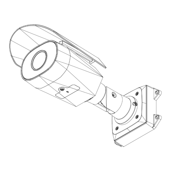
Page 10: Side View
Side View 1. Sun shroud An adjustable cover to help protect the lens against glare from the sun. 2. Mount arm Adjustable mount arm for positioning the camera. 3. Adjustment screws Provides a locking mechanism for the mount arm. Side View... -
Page 11: Installation
Follow these precautions to avoid camera issues when installing in a salt heavy environment: Use mounting accessories offered by Avigilon. All Avigilon accessories are tested to work with Avigilon cameras in the rated environments. ... -
Page 12: Mounting And Aiming Video Analytics Cameras
Setting the Time Configuring the Camera Mounting and Aiming Video Analytics Cameras When installing an Avigilon video analytics camera, follow the listed mounting and aiming recommendations to maximize the camera's analytics capabilities: The camera should be installed above 274 cm (9'). -
Page 13: (Optional) Removing The Sun Shroud
NOTE: It is recommended that silicone sealant be applied around the edge of the mounting bracket to prevent moisture from entering the mounting surface. 4. Insert the mounting hooks on the rear of the camera into the mounting hook slots on the mounting bracket, then let the camera hang. -
Page 14: Mounting The Camera
3. Install the protective cable boot. You may choose to skip this step if you are using the optional junction box. a. Remove the protective cable boot that is preinstalled over the Ethernet port, then thread one end of the Ethernet cable through it. Ensure the orientation of the cable and boot matches the one shown in the image. -
Page 15: Removing The Configuration Panel Cover
1. Tuck the extra lengths of cables into the cable entry hole. 2. Secure the camera to the mounting bracket: a. Raise the camera until it covers the mounting bracket. b. Use the camera mounting screws to fasten the camera to the bracket. Removing the Configuration Panel Cover 1. -
Page 16: (Optional) Using The Usb Wi-Fi Adapter
For more information about configuring the camera from the mobile web interface see Avigilon USB Wi-Fi Adapter System User Guide. NOTE: The camera will reserve the 10.11.22.32/28 subnet for internal use while the USB Wi-Fi Adapter is plugged in. -
Page 17: Zooming And Focusing The Camera
4. Tighten the adjustment screws on the mount arm to secure the camera’s position. 5. In the camera web browser interface or the Avigilon Control Center software adjust the camera’s Image and Display settings. You can set the zoom position, focus and change the image rotation. -
Page 18: Setting The Time
For more information, see the Avigilon H.264 Web Interface User Guide. If you installed an H4 ES camera, you can use the Avigilon Control Center Client software to configure the camera and the embedded software. For More Information Additional information about setting up and using the device is available in the following guides: ... -
Page 19: Connecting To Power And External Devices
Connecting to Power and External Devices Important: Be careful not to connect auxiliary power to the audio input wire or the camera will be damaged. Although both the audio input wire and auxiliary power wire are brown, the auxiliary power wire is distinguished by its thicker wire gauge and AUX PWR label. - Page 20 6. Pink — Digital Output 7. Purple — Reserved Wire, do not connect. 8. White — Reserved Wire, do not connect. * — Relay ** — Switch M — Microphone S — Speaker AUX1 — Brown Auxiliary Power Wire, labeled AUX PWR ...
-
Page 21: Led Indicators
LED Indicators Once connected to the network, the Connection Status LED will display the progress in connecting to the Network Video Management software. The following table describes what the LEDs indicate: Connection Status Connection State Description One short flash every Obtaining IP Address Attempting to obtain an IP address. -
Page 22: Resetting To Factory Default Settings
Resetting to Factory Default Settings If the camera no longer functions as expected, you can choose to reset the camera to its factory default settings. Use the firmware revert button to reset the camera. The firmware revert button is shown in the following diagram: NOTE: For the ES camera models, resetting the camera will erase all recorded video from the camera. -
Page 23: Setting The Ip Address Using The Arp/Ping Method
NOTE: The ARP/Ping Method will not work if the Disable setting static IP address through ARP/Ping method check box is selected in the camera's web browser interface. For more information, see the Avigilon™ High Definition H.264 Web Interface User Guide. -
Page 24: Specifications
Specifications Camera Audio Input/Output Line level input and output H4A-BO1-IR: (1 – 3 MP models) 3-9 mm, F1.3, P-iris (5 – 8 MP models) 4.3-8 mm, F1.8, P-iris Lens H4A-BO2-IR: (1 – 5 MP models) 9-22 mm, F1.6, P-iris SD Storage (Models with SD card SD/SDHC/SDXC slot –... - Page 25 Cable Length 45 cm (17.72”) Electrical Power Consumption 13 W VDC: 12 V +/- 10%, 13 W min Power Source VAC: 24 V +/- 10%, 19 VA min PoE: IEEE802.3af Class 3 RTC Backup Battery 3V manganese lithium Environmental -40 °C to +55 °C (-40 °F to 131 °F) Operating 8.0 MP model —...
-
Page 26: Limited Warranty And Technical Support
Limited Warranty and Technical Support Avigilon warranty terms for this product is provided at avigilon.com/warranty. Warranty service and technical support can be obtained by contacting Avigilon Technical Support: avigilon.com/contact-us/. Limited Warranty and Technical Support...
Need help?
Do you have a question about the H4A-G-BO1-IR and is the answer not in the manual?
Questions and answers