Avigilon H4 Installation Manual
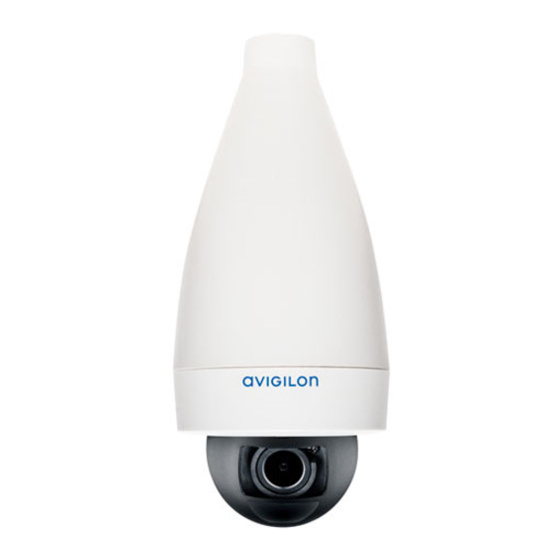
Mini dome camera with pendant mount adapter
Hide thumbs
Also See for H4:
- Installation manual (46 pages) ,
- Installation manuals (26 pages) ,
- User manual (52 pages)

Related Manuals for Avigilon H4


Summary of Contents for Avigilon H4
- Page 1 Installation Guide Avigilon H4 Mini Dome Camera Models with Pendant Mount Adapter: H4M-D plus H4M-MT-NPTA...
- Page 2 Do not use strong or abrasive detergents when cleaning the device body. Use only accessories recommended by Avigilon. Regulatory Notices This device complies with part 15 of the FCC Rules. Operation is subject to the following two conditions: (1) this device may not cause harmful interference, and (2) this device must accept any interference...
- Page 3 © 2019, Avigilon Corporation. All rights reserved. AVIGILON, the AVIGILON logo, AVIGILON CONTROL CENTER, and ACC are trademarks of Avigilon Corporation. ONVIF is a trademark of Onvif, Inc. Other names or logos mentioned herein may be the trademarks of their respective owners. The absence of the symbols ™...
- Page 4 (2) is responsible for your use of, or reliance on, the information. Avigilon Corporation shall not be responsible for any losses or damages (including consequential damages) caused by reliance on the information presented herein.
-
Page 5: Table Of Contents
Table of Contents Overview Cover View Pendant Mounting Adapter View Camera Body View Installation Required Tools and Materials Camera Package Contents Using the Pendant Mounting Adapter Installing the Camera Base to the Mounting Adapter Initializing a Camera Username and Password Assigning an IP Address Accessing the Live Video Stream Aiming the Camera... -
Page 6: Overview
Overview Note: Be careful not to scratch the camera. The resulting marks or fingerprints may affect the overall image quality. Keep the protective covers on the outside of the camera until the installation is complete. Cover View 1. Camera body The main body of the camera, including the internal mechanisms for aiming the camera. -
Page 7: Pendant Mounting Adapter View
Pendant Mounting Adapter View 1. Cable entry hole An entry hole for the cables required for camera operation. 2. Camera attachment slots Slots that the camera housing clips are inserted into to attach the camera body to the mounting adapter. 3. -
Page 8: Camera Body View
Camera Body View 1. Ethernet port Accepts power and Ethernet connection to the network. The camera can only be powered by Power over Ethernet (PoE). Server communication and image data transmission also occur over this connection. 2. Camera housing clips Clips that attach the camera body to the mounting adapter. - Page 9 Provides information about device operation. For more information, see Connection Status LED Indicator on page 20. 7. Firmware revert button Used to reset the camera. For more information, see Resetting to Factory Default Settings on page 22. 8. Serial number tag Provides the serial number and MAC address for the camera. Camera Body View...
-
Page 10: Installation
2 screws and anchors for solid walls Ensure the low-profile pendent mounting adapter package (H4M-MT-NPTA1) contains the following: Pendant mounting adapter for an H4 Mini Dome Camera Pendant mount bezel (same as Surface mount bezel) 2 screws for pendant mounting adapter... - Page 11 1. Place the NPT adapter against the hanging NPT pipe and rotate clockwise. 2. Pull ethernet cable through the pendant adapter. Using the Pendant Mounting Adapter...
- Page 12 3. Align camera attachment slots on the wall plate with the snaps on the NPT adapter and push into place such that the snaps are engaged and the wall plate is held firmly. 4. Drive two screws to fasten the wall plate to the NPT adapter. Using the Pendant Mounting Adapter...
-
Page 13: Installing The Camera Base To The Mounting Adapter
Installing the Camera Base to the Mounting Adapter Note: Be careful not to scratch or touch the dome bubble. The resulting marks or fingerprints may affect the overall image quality. Keep the protective covers on the outside of the dome bubble until the installation is complete. -
Page 14: Assigning An Ip Address
For more information, see the Avigilon Blue Subscriber or Dealer User Guides. Tip: If you are connecting your Avigilon camera to a 3rd party VMS, you will need to set up the first user through the camera's Web Interface, Camera Configuration Tool, or USB Wifi Adapter before you connect to the 3rd party VMS. -
Page 15: Accessing The Live Video Stream
Device's web browser interface: http://<camera IP address>/. Network Video Management software application (for example, the Avigilon Control Center™ software). ARP/Ping method. For more information, see Setting the IP Address Using the ARP/Ping Method on page 23. Note: Depending on the manufacture date of your camera, you will have one of the two options below to... -
Page 16: Aiming The Camera
Aiming the Camera Note: When you are aiming the camera, reference the live stream for the camera. 1. Unlock the orange locking latch on the camera base if it is already locked. The lens should be pointing in the general direction of the intended view. The arrow indicator between the optical window and the camera base indicates the top of the view. -
Page 17: Attaching The Bezel
4. In the camera web browser interface or the Avigilon Control Center software, adjust the camera’s Image and Display settings. Attaching the Bezel After you lock the camera in place, attach the bezel to the mounting adapter, by completing the following... - Page 18 1. Locate the two plastic features on the interior of the bezel. 3. Rotate the bezel clockwise until it snaps into place. Attaching the Bezel...
-
Page 19: Configuring The Camera
For more information, see the Avigilon Camera Configuration Tool User Guide. If the camera is connected to the Avigilon Control Center system, you can use the client software to configure the camera. For more information, see the Avigilon Control Center Client User Guide. -
Page 20: Connection Status Led Indicator
Connected to the Network Video Management software or an ACC™ Server. The default connected setting can be changed to Off using the camera's web user interface. For more information see the Avigilon High Definition H4 and H5 IP Camera Web Interface User Guide. Connection Status LED Indicator... -
Page 21: Removing The Camera From The Mounting Adapter
Removing the Camera from the Mounting Adapter 1. Twist the bezel counter-clockwise until it releases. Some force will be required to release the bezel and you will hear a click as it is released. 2. Pinch the camera housing clips in the attachment slots to release the camera body from the pendant mount and pull the camera out of the mount. -
Page 22: Resetting To Factory Default Settings
Resetting to Factory Default Settings If the device no longer functions as expected, you can choose to reset the device to its factory default settings. Use the firmware revert button to reset the device. The firmware revert button is shown in the following diagram: 1. -
Page 23: Setting The Ip Address Using The Arp/Ping Method
For more information, see the Avigilon High Definition H4 and H5 IP Camera Web Interface User Guide. 1. Locate and make note of the MAC Address (MAC) listed on the Serial Number Tag for reference. -
Page 24: Specifications
Specifications Camera Lens 2.8mm, F1.2, IR Corrected HFOV (Angle of 1.3 MP: (5:4) 74°; (16:9) 110° View) 2.0 MP: (5:4) 74°; (16:9) 110° 3.0 MP: (5:4) 94°; (16:9) 100°, (4:3) 100° Network Network 100Base-TX Cabling Type CAT5 Connector RJ-45 ONVIF® ONVIF compliant with version 1.02, 2.00, Profile S (www.onvif.org) Security Password protection, HTTPS encryption, digest authentication, WS authentication, user access log, 802.1x port based authentication... - Page 25 Power Consumption 4 W Power Source PoE: IEEE802.3af Class 2 compliant RTC Backup Battery 3V manganese lithium Environmental Operating 0 °C to 50 °C (32 °F to 122 °F) Temperature Storage -30 °C to 70 °C (-22 °F to 158 °F) Temperature Humidity 0-95% non-condensing...
-
Page 26: Limited Warranty And Technical Support
Limited Warranty and Technical Support Avigilon warranty terms for this product are provided at avigilon.com/warranty. Warranty service and technical support can be obtained by contacting Avigilon Technical Support: avigilon.com/contact-us/. Limited Warranty and Technical Support...
Need help?
Do you have a question about the H4 and is the answer not in the manual?
Questions and answers