Avigilon H4 Installation Manuals
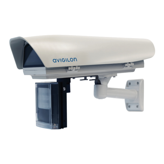
License plate capture camera
Hide thumbs
Also See for H4:
- Installation manual (46 pages) ,
- User manual (52 pages) ,
- Interface user manual (45 pages)
Table of Contents
Advertisement
Quick Links
Advertisement
Table of Contents

Subscribe to Our Youtube Channel
Related Manuals for Avigilon H4


Summary of Contents for Avigilon H4
- Page 1 Installation Guide Avigilon H4 License Plate Capture Camera...
- Page 2 Do not use strong or abrasive detergents when cleaning the device body. Use only accessories recommended by Avigilon. This product should be installed in restricted access locations. WARNING — The electrical system to which the unit is connected must be equipped with an automatic bipolar circuit breaker.
- Page 3 The manufacturer declines all responsibility for any damage caused by an improper use of the appliances mentioned in this manual. Furthermore, the manufacturer reserves the right to modify its contents without any prior notice. The documentation contained in this manual has been collected with great care. The manufacturer, however, cannot take any liability for its use.
- Page 4 Connect the equipment into an outlet on a circuit different from that to which the receiver is connected. Consult the dealer or an experienced radio/TV technician for help. Changes or modifications made to this equipment not expressly approved by Avigilon Corporation or parties authorized by Avigilon Corporation could void the user’s authority to operate this equipment.
- Page 5 Avigilon Corporation reserves the right to make any such changes without notice. Neither Avigilon Corporation nor any of its affiliated companies: (1) guarantees the completeness or accuracy of the information contained in this document; or (2) is responsible for your use of, or reliance on, the information.
-
Page 6: Table Of Contents
Table of Contents Overview Product Description and Type Designation Unpacking Safely Disposing of Packaging Material Preparing the Product for Use Attaching the Bracket Installation Housing Package Contents Mounting the LPC Enclosure Mounting the Feed Through Mounting Arm Installing the IR Illuminator Mounting the Optional ES-HD-MNT-PAR Parapet Mounting Adapter Installing the IR Illuminator Connecting the Cables... -
Page 7: Overview
This guide provides instructions on how to install an H4 License Plate Capture (LPC) camera using the Avigilon H4 LPC Camera Kit. For information on how to select an appropriate mounting location and to set up the IR illuminator, see the H4 LPC Site Design Guide. -
Page 8: Attaching The Bracket
Attaching the Bracket CAUTION — The product must be fastened with suitable equipment. The fastening means must guarantee the mechanical seal when a force equal to at least 4 times the weight of the device is applied. Attaching the Bracket... -
Page 9: Installation
For information on how to use the License Plate Recognition feature in the Avigilon Control Center (ACC), see the Avigilon Control Center Client User Guide. Use this manual to install the H4 LPC Camera Kit after you have selected a mounting location as per the site design guidelines (see the H4 LPC Site Design Guide). -
Page 10: Mounting The Feed Through Mounting Arm
Mounting the Feed Through Mounting Arm Complete the following steps to mount the enclosure using the included feed through mounting arm: 1. Drill four mounting holes and a cable entry hole into the mounting surface. 2. Attach the mounting bracket to the mounting surface. Use screws that are appropriate for the mounting surface. - Page 11 b. The PoE cable will be routed through the largest cable opening on the bottom of the enclosure. c. Use the sealing ring to seal the cable connection through the enclosure. Ensure that the unused holes on the bottom of the housing are sealed with the remaining sealing rings to prevent water from entering the housing.
-
Page 12: Installing The Ir Illuminator
4. Use the provided screws to secure the enclosure to the mounting arm. Installing the IR Illuminator 1. Refer to the H4 LPC Site Design Guide to determine if the IR illuminator's lens needs to be changed or removed. Please consult the IR illuminator manual for instructions on replacing the lens, if required. - Page 13 3. Use the included screws to secure the IR illuminator to the housing. Be sure to use the IR bracket screw holes indicated in the image below 4. Tighten the screws using the provided allen wrench. Installing the IR Illuminator...
-
Page 14: Mounting The Optional Es-Hd-Mnt-Par Parapet Mounting Adapter
Installing the IR Illuminator 1. Refer to the H4 LPC Site Design Guide to determine if the IR illuminator's lens needs to be changed or removed. Please consult the IR illuminator manual for instructions on replacing the lens, if required. - Page 15 1. Pull the required PoE cable from the Power Injector. The PoE cable will be routed through the largest cable opening on the bottom of the enclosure. 2. Use the sealing ring to seal the cable connection through the enclosure. Ensure that the unused holes on the bottom of the housing are sealed with the remaining sealing rings to prevent water from entering the housing.
-
Page 16: Installing The Camera
Installing the Camera Complete the following steps to install the camera into the enclosure: 1. Loosen the 2 screws on the side of the enclosure using the provided allen key. Open the housing as shown in the diagram below. NOTE: After installation and wiring is complete, make sure to close the housing securely. 2. - Page 17 3. Mount the camera to the PoE module using the supplied scew (1), washer, and spacer (2). Apply at least one spacer to guarantee electrical isolation between the PoE module and the camera. a. The spacer should be positioned in the second slot, as shown in the image below. Slide the camera and spacer as close to the front as possible to avoid visual interference or optical reflections from the glass.
-
Page 18: Powering Up
5. Re-attach the PoE module with the camera back to the housing and tighten the previously loosened screws. 6. Make sure to set the dip switch SW1 to the ON position. Remove the protective lens film from the camera before closing the housing. Absorbed Power Configuration Maximum Power PoE Class 3 (13W max) - Page 19 The LEDs shown in the figure below allow users to check the operating status of the camera and enclosure. Refer to the table below for the operating status indicators. Operating Status LED Status Apparatus Status The device is not powered. LD1 (Power Supply) The device is correctly powered.
-
Page 20: Adjusting The Mounting Bracket
Adjusting the Mounting Bracket 1. Use the 4mm Hex key provided to loosen the screw at the head of the mounting bracket. 2. Adjust the head as required. 3. Tighten the screw to secure the head. Cleaning and Maintenance CAUTION — Do not clean glass window with ethyl alcohol, solvents, hydrogenated hydrocarbide, strong acid, or alkali. -
Page 21: For More Information
For More Information Additional information about setting up and using the device is available in the following guides: Avigilon H4 License Plate Capture (LPC) Camera Site Design Guide Avigilon Control Center Client User Guide Web Interface User Guide — Avigilon High Definition H.264 IP Cameras... -
Page 22: Specifications
Specifications General Specifications Maximum Capture Speed 100 km/h (62 mph) Minimum Illumination 0 lux IR Illumination 850 nm, continuous, field adjustable angle Single Lane: 30 m (100 ft) Maximum IR Illumination Distance Dual Lane: 12 m (40 ft) Operating Temperature Range -30 °C to 50 °C (-22 °F to 122 °F) Cold Start Delay Up to 1.5 hours... - Page 23 Privacy Zones Up to 64 zones Audio Compression Method G.711 PCM 8 kHz Audio Input/Output Line level input/output, A/V mini-jack (3.5 mm) External I/O Terminals Alarm In, Alarm Out USB Port USB 2.0 Micro Network Network 100BASE-TX Cabling Type CAT5 Connector RJ-45 ONVIF...
-
Page 24: Enclosure Specifications
Enclosure Specifications The following specifications are for the enclosure, ES-HD-LP-HS. Mechanical Dimensions (W×H×L) 176 mm × 160 mm × 514 mm (6.9" × 6.3" × 20.2") Internal Usable Area (W×H×L) 100 mm × 70 mm × 250 mm (4.6" × 2.7" × 9.8") Weight 3.1 kg (6.6 lbs) Window Material... - Page 25 UL 1598, UL 2108, UL 8750, CSA C22.2 No. 250.0, EN 60598-1, Safety EN 60598-2-1, EN 62471 (Risk Group 2) Electromagnetic Emissions FCC Part 15 Subpart B Class B, EN 55015 Electromagnetic Immunity FCC Part 15 Subpart B Class B, EN 61547 Environmental IP 66 IR Illuminator Specifications...
-
Page 26: Limited Warranty And Technical Support
Limited Warranty and Technical Support Avigilon warranty terms for this product is provided at avigilon.com/warranty. Warranty service and technical support can be obtained by contacting Avigilon Technical Support: avigilon.com/contact-us/. Limited Warranty and Technical Support...
Need help?
Do you have a question about the H4 and is the answer not in the manual?
Questions and answers