Table of Contents
Advertisement
Quick Links
5 MP Dome & Turret & Bullet
User Manual
Thank you for purchasing our product. If there are any
questions, or requests, do not hesitate to contact the
dealer.
This manual applies to the models below:
Type
Type I
Type II
Type III
Type IV
Type V
This manual may contain several technical mistakes or
printing errors, and the content is subject to change
without notice. The updates will be added to the new
version of this manual. We will readily improve or
update the products or procedures described in the
manual.
TURBO HD
User Manual
Model
DS-2CE57H0T-VPITE(C)
DS-2CE78H0T-IT3E(C)
DS-2CE76H0T-ITME(C)
DS-2CE16H0T-ITE(C)
DS-2CE17H0T-IT3E(C)
Camera
010000221119
Advertisement
Table of Contents

Subscribe to Our Youtube Channel
Related Manuals for HIKVISION TURBO HD DS-2CE57H0T-VPITE


Summary of Contents for HIKVISION TURBO HD DS-2CE57H0T-VPITE
- Page 1 TURBO HD 5 MP Dome & Turret & Bullet Camera User Manual User Manual Thank you for purchasing our product. If there are any questions, or requests, do not hesitate to contact the dealer. This manual applies to the models below: Type Model Type I...
- Page 2 The information contained in the Manual is subject to change, without notice, due to firmware updates or other reasons. Please find the latest version of this Manual at the Hikvision website (https://www.hikvision.com/). Please use this Manual with the guidance and assistance of professionals trained in supporting the Product.
- Page 3 UNSAFE NUCLEAR FUEL-CYCLE, OR IN SUPPORT OF HUMAN RIGHTS ABUSES. IN THE EVENT OF ANY CONFLICTS BETWEEN THIS MANUAL AND THE APPLICABLE LAW, THE LATTER PREVAILS. Regulatory Information FCC Information Please take attention that changes or modification not expressly approved by the party responsible for compliance could void the user’s authority to operate the equipment.
- Page 4 Safety Instruction These instructions are intended to ensure that user can use the product correctly to avoid danger or property loss. The precaution measure is divided into “Warnings” and “Cautions”. Warnings: Serious injury or death may occur if any of the warnings are neglected.
- Page 5 No naked flame sources, such as lighted candles, should be placed on the equipment. Install the equipment according to the instructions in this manual. To prevent injury, this equipment must be securely attached to the wall in accordance with the installation instructions.
-
Page 6: Table Of Contents
TABLE OF CONTENTS 1 Introduction ................. 1 1.1 Product Features ............1 1.2 Overview ..............1 1.2.1 Overview of Type I Camera ........ 1 1.2.2 Overview of Type II Camera ....... 1 1.2.3 Overview of Type III Camera ......1 1.2.4 Overview of Type IV Camera ...... -
Page 7: Introduction
1 Introduction 1.1 Product Features The main features are as follows: High performance CMOS sensor Smart IR Power over coaxial cable IR cut filter with auto switch OSD menu with configurable parameters Auto white balance ... -
Page 8: Overview Of Type Iv Camera
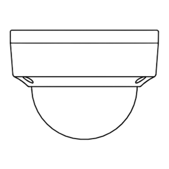
1.2.4 Overview of Type IV Camera Figure 1-4 Overview of Type IV Camera 1.2.5 Overview of Type V Camera Power Cord Bracket Video Cable Main Body Lens Figure 1-5 Overview of Type V Camera 2 Installation Before you start Make sure that the device in the package is in good ... - Page 9 Figure 2-2 Remove the Bubble 4. Fix the mounting base on the ceiling with supplied screws. Figure 2-3 Fix the Mounting Base 5. Route the cables through the cable hole, or the side opening. 6. Connect the cables. 7. Power on the camera to check whether the image on the monitor is gotten from the optimum angle.
-
Page 10: Ceiling Mounting With Junction Box
2.1.2 Ceiling Mounting with Junction Box Before you start: You need to purchase an inclined ceiling mount separately. Steps: 1. Paste the drill template to the ceiling. 2. Drill 2 screw holes and the cable hole in the ceiling according to the drill template. 3. -
Page 11: Pendant Mounting
Wall Mounting with Aluminum Alloy Bracket Steps: 1. Install the bracket. 1) Install the bracket on the wall with four M6 × 75 expansion bolts. 2) Rotate the installation adapter to the bracket. 3) Tighten the M4 × 6 screw. M4 ×... -
Page 12: Installation Of Type Ii Camera
7. Refer to steps 6 to 8 of 2.1.1 Ceiling Mounting without Junction Box to finish the installation. Figure 2-14 Finish Installation 2.2 Installation of Type II Camera 2.2.1 Ceiling/Wall Mounting without Junction Box Before you start: The installation of ceiling mounting and wall mounting are similar. -
Page 13: Ceiling/Wall Mounting With Junction Box
Figure 2-18 3-Axis Adjustment 2.2.2 Ceiling/Wall Mounting with Junction Box Before you start: You need to purchase a junction box in advance. Steps: 1. Paste the drill template on the ceiling/wall. 2. Drill screw holes and the cable hole according to the drill template. -
Page 14: Installation Of Type Iii Camera
Figure 2-22 Combine the Junction Box’s Cover and Body 8. Repeat the step 5 to 7 of 2.2.1 Ceiling/Wall Mounting without Junction Box to finish the installation. 2.3 Installation of Type III Camera 2.3.1 Ceiling/Wall Mounting without Junction Box Before you start: The ceiling mounting and the wall mounting are similar. -
Page 15: Ceiling/Wall Mounting With Junction Box
Figure 2-25 Secure the Camera 7. Connect the corresponding cables, such as power cord, and video cable. 8. Power on the camera to check whether the image on the monitor is gotten from the optimum angle. If not, adjust the camera according to the figure below. -
Page 16: Installation Of Type Iv & V Camera
Figure 2-29 Secure the Junction Box’s Body 6. Route the cables through the bottom cable hole, or the side cable hole of the junction box. 7. Combine the junction box cover and its body with three M3 screws. Figure 2-30 Combine the Junction Box 8. -
Page 17: Ceiling/Wall Mounting With Junction Box
Pan Position [0° to 360°] Trim Ring Rotation Position Tilt Position [0° [0° to 360°] to 180°] Type III Pan Position [0° to 360°] Trim Ring Rotation Position Tilt Position [0° to 360°] [0° to 180°] Type IV Figure 2-32 3-axis Adjustment 1). -
Page 18: Menu Description
6. Combine the junction box cover with its body. Type III Type IV Figure 2-35 Combine the Junction Box Cover and Body 7. Repeat the step 4 to 6 of 2.4.1 Ceiling/Wall Mounting without Junction Box 2.1.1 to finish the installation. -
Page 19: Video Format
VIDEO FORMAT EXPOSURE MODE SHUTTER BACK EXPOSURE EXIT SAVE & EXIT MODE IR LIGHT DAY/NIGHT SMART IR D->N THRESHOLD N->D THRESHOLD BACK EXIT SAVE & EXIT IMAGE MODE MAIN MENU WHITE BALANCE BRIGHTNESS CONTRAST SHARPNESS VIDEO SATURATION SETTINGS BACK EXIT SAVE &... -
Page 20: Day/Night
HLC (Highlight Compensation) HLC stands for highlight compensation. The camera detects the strong spots (the over-exposure portion of image), then reduce the brightness of the strong spots to improve the overall images. DWDR (Digital Wide Dynamic Range) Digital wide dynamic range gives the camera the ability to view dark areas of the given image as well as extremely lighted portions of the image, or areas of high contrast. -
Page 21: Video Settings
Figure 3-4 DAY/NIGHT IR LIGHT You can turn on/off the IR LIGHT to meet the requirements of different circumstances. SMART IR The Smart IR function is used to adjust the light to its most suitable intensity, and prevent the image from over exposure. -
Page 22: Factory Default
You can set the R-GAIN/B-GAIN value to adjust the shades of red/blue color of the image. WHITE BALANCE MODE MANUAL R-GAIN B-GAIN BACK EXIT SAVE&EXIT Figure 3-6 MWB MODE BRIGHTNESS Brightness refers to the brightness of the image. You can set the brightness value from 1 to 9 to darken or brighten the image.
Need help?
Do you have a question about the TURBO HD DS-2CE57H0T-VPITE and is the answer not in the manual?
Questions and answers