Dell EMC PowerEdge MX7000 Field Service Manual
Hide thumbs
Also See for EMC PowerEdge MX7000:
- Installation and service manual (68 pages) ,
- Manual (48 pages) ,
- Quick start manual (9 pages)

Related Manuals for Dell EMC PowerEdge MX7000


Summary of Contents for Dell EMC PowerEdge MX7000
- Page 1 Dell EMC PowerEdge MX7000 Enclosure Field Service Manual Regulatory Model: E44S Series Regulatory Type: E44S001 April 2021 Rev. A06...
- Page 2 A WARNING indicates a potential for property damage, personal injury, or death. © 2018 2021 Dell Inc. or its subsidiaries. All rights reserved. Dell, EMC, and other trademarks are trademarks of Dell Inc. or its subsidiaries. Other trademarks may be trademarks of their respective owners.
-
Page 3: Table Of Contents
Contents Chapter 1: Product overview......................5 PowerEdge MX architecture overview.......................... 5 Product features..................................6 Product comparison................................6 Chapter 2: Field service information....................8 Field service overview................................ 8 Enclosure overview................................8 Front view of the enclosure............................9 Back view of the enclosure............................12 Safety precautions................................13 Recommended tools................................18 Need to know..................................18 Critical call-outs................................18... - Page 4 Particulate and gaseous contamination specifications ..................81 Chapter 6: Getting help.......................83 Locating the information tag of your system......................83 Contacting Dell EMC................................ 83 Documentation feedback..............................84 Accessing system information by using QRL......................84 Quick Resource Locator for PowerEdge MX7000 enclosure................84 Receiving automated support with SupportAssist ....................
-
Page 5: Chapter 1: Product Overview
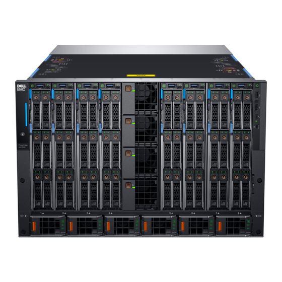
Product overview The PowerEdge MX7000 enclosure replaces the M1000e chassis. The enclosure is designed for compute and storage sleds which are front mounted and vertically oriented. The MX7000 enclosure supports 8 single-width or 4 double-width front-loading sleds, 6 hot-swap front-loading power supplies, 3 I/O fabrics, 5 rear and 4 front accessible hot-swap cooling fans, and has a front panel with an optional LCD panel. -
Page 6: Product Features
● A hardened design to protect, detect, and recover underlying infrastructure from cyber attacks For more information about these modules and sleds, see their documents which are available at www.dell.com/ poweredgemanuals. Product features The MX7000 enclosure has the following features: ●... - Page 7 Table 1. Feature comparison (continued) Feature MX7000 M1000e Power Supplies 6 x 3 kW 6 x 3 kW Integrated with the Management Discrete design module Product overview...
-
Page 8: Chapter 2: Field Service Information
● Quick Resource Locator – information about the Quick Resource Locator (QRL) feature. Enclosure overview The Dell EMC PowerEdge MX7000 is the next-generation M1000e follow-on chassis and a revolutionary architecture set to be the future foundation of modular architecture. The PowerEdge MX7000 enclosure is a 7U chassis that supports:... -
Page 9: Front View Of The Enclosure
● Up to eight standard height, single-width sleds, or four standard height, double-width sleds. Up to seven Storage sleds can be populated in the enclosure. NOTE: One compute node must be present and it must be mapped to a storage node. ●... - Page 10 Left control panel Figure 3. Left control panel - Status LED Table 2. Left control panel - LED indicator description Indicator Description Status System health Blinks amber for 2 seconds and is OFF for 1 second when the chassis health has degraded. By default, the LED is unlit.
- Page 11 Table 3. Left control panel - LCD panel description Indicator Description Status LCD with Quick LCD enabled with Quick Sync module Sync LCD without LCD without Quick Sync module Quick Sync System ID This option is a button/indicator on the LCD panel to identify the chassis, or choose specific indicator on LCD sleds to identify.
-
Page 12: Back View Of The Enclosure
Right control panel Figure 5. Right control panel 1. Power button 2. USB 2.0 port (2) 3. iDRAC Direct port (Micro-AB USB) 4. Mini DisplayPort NOTE: For more information on the ports, see Technical specifications. Back view of the enclosure Figure 6. -
Page 13: Safety Precautions
Standby power When applicable Dell products that feature a standby power mode, must be unplugged before the system is serviced. NOTE: Systems that incorporate standby power, continue to use power even when they are powered off. For example, standby power enables the system to be powered on remotely with the wake on LAN feature enabled, suspended into sleep mode, or other advanced power management features. - Page 14 Due to the increased density of semiconductors that are used in recent Dell products, the sensitivity to static damage is now higher than in earlier Dell products. For this reason, some previously approved methods of handling parts are no longer applicable.
- Page 15 ESD Wrist Strap tester The wires inside an ESD strap are prone to damage over time. When using an unmonitored kit, Dell recommends to regularly test the strap before each service call, and at a minimum, test once per week. A Wrist Strap tester is the best method for...
- Page 16 A green LED lights up if the test is successful; a red LED lights up and an alarm sounds if the test fails. Figure 12. Wrist Strap tester Insulator elements Dell recommends to place ESD sensitive devices, such as plastic heat sink casings, away from internal components that are insulators and highly charged. Table 4. Placement of insulator elements ...
- Page 17 Figure 13. ESD packaging Transporting sensitive components When transporting ESD sensitive components such as replacement parts or returned parts to Dell, it is critical to place these parts in antistatic bags for safe transport. ESD protection summary It is suggested that all field service engineers use the traditional wired ESD grounding Wrist Strap and protective antistatic mat when servicing Dell products.
-
Page 18: Recommended Tools
6. Keep your back upright, whether lifting or setting down the load. Do not add the weight of your body to the load. Avoid twisting your body and back. 7. Follow the same techniques in reverse to set the load down. Recommended tools Table 5. -
Page 19: Version Control
Site. System diagnostics and indicator codes The diagnostic indicators on the system front panel display system status during system startup. The following sections contain information about the chassis LEDs and indicator codes for Dell EMC PowerEdgeMX7000 system. Field service information... -
Page 20: Psu Indicators
PSU indicators Figure 14. PSU indicators 1. PSU health indicator 2. AC supply status indicator 3. DC output status indicator Table 6. PSU health indicator codes PSU health indicator Indicator state PSU functioning normally Green PSU faulty Blinking amber PSU mismatch ON for 1 second, and then 5 blinks and OFF (non-repeating cycle). -
Page 21: Management Module Indicator Codes
Figure 16. Rear fan module Table 9. Fan module indicator codes Fan indicators Indicator state Fan functioning normally - Front/ Rear Solid green Fan failure Blinks amber 2 seconds and 1 second OFF NOTE: When the chassis is powered off with the AC connection that is powered on, only the rear fans are powered off. Management module indicator codes Figure 17. -
Page 22: Disassembly And Reassembly
Table 10. Management module indicator behavior (continued) Status Indicator combination Failed chassis/ Management module: Mode Power indicator OFF, status indicator Amber-solid NOTE: ● The management module starts boot but is unable to boot to one or more operating system partitions. ● The management module boots but detects a failure such as a network switch failure, or a voltage regulator failure. - Page 23 Figure 18. Removing a sled blank Installing a sled blank Steps 1. Align the sled blank with the bay in the enclosure. 2. Insert and push the sled blank, until it locks into place. NOTE: Install two sled blanks when a double-width sled is removed. Field service information...
- Page 24 Figure 19. Installing a sled blank Removing a compute or storage sled from the enclosure Prerequisites 1. Power off the sled. CAUTION: Ensure the compute sleds mapped to the storage sleds are powered off. CAUTION: Remove the storage sled only when the hard drive LED is off. NOTE: If the storage sled drive LED indicator is off, it indicates that all the compute sleds mapped to the storage sled are powered off.
- Page 25 CAUTION: Ensure that the sled is supported with both hands while you are removing the sled. Figure 20. Removing a storage sled from an enclosure Figure 21. Removing a single-width compute sled from the enclosure 3. Install the I/O connector cover on the sled. Field service information...
- Page 26 Installing a compute or storage sled into the enclosure Prerequisites 1. Ensure that the sled release lever is in the open position. Steps 1. Remove the I/O connector cover from the sled. Figure 22. Removing the I/O cover 2. Hold and align the sled with the bay in the enclosure. 3.
- Page 27 Figure 23. Installing a single-width compute sled into the enclosure Figure 24. Installing a storage sled into the enclosure Next steps 1. Power on the sled. Field service information...
-
Page 28: Cooling Fan Modules
Cooling fan modules NOTE: The system must be populated with the full set of fans to support the airflow requirements of the chassis. Removing a front fan module Steps 1. Press the release button to release the fan module. 2. Hold and pull the fan module out of the fan bay. Figure 25. - Page 29 Figure 26. Installing the front fan module Removing a rear fan module Steps 1. Press the release button to release the fan module. 2. Hold and pull the fan module out of the fan bay. Figure 27. Removing a rear fan module Field service information...
-
Page 30: Power Supply Units
Installing a rear fan module Steps 1. Insert the fan module into the fan bay. 2. Push the fan module into the fan bay, until it locks into place. NOTE: Ensure that the green LED on the fan module is illuminated, indicating that the module is functioning properly. Figure 28. -
Page 31: Control Panel
Figure 29. Removing a power supply unit Installing a power supply unit Steps 1. Push the PSU into the enclosure until it is seated firmly. 2. Close the PSU release lever to secure the PSU in the bay. Figure 30. Installing a power supply unit Control panel NOTE: Ensure to backup the chassis configuration and the compute sleds configuration before replacing the right control... - Page 32 WARNING: Due to the weight of a fully populated MX7000 enclosure chassis, never install or pull a full chassis out of a rack with ReadyRails. First remove each component before you lift or remove the chassis. ● Right control panel module ●...
- Page 33 The above RCP replacement procedure will result in loss of some configuration stored on RCP. Backup/Restore (Step #1/#4,#5) if successfully executed will restore some configuration but not all. Customer will have to reconfigure chassis including any network fabric configuration for Dell switches. NOTE: RCP replacement will result in new IP address if DHCP was enabled.
- Page 34 Figure 31. Disconnecting the right control panel cable 4. Remove the screws that secure the right control panel cable cover to the chassis and remove it from the enclosure. 5. Remove the screws that secure the right control panel ear to the chassis. 6.
- Page 35 Steps 1. Connect the right control panel cable to the control panel board. 2. Align the right control panel ear with the enclosure. 3. Fasten the screws to secure the right control panel ear to the chassis. 4. Fasten the screws to secure the right control panel cable cover to the chassis. Figure 33.
- Page 36 Backing up the chassis configuration About this task You must backup the chassis configuration and the compute sleds configuration in the chassis for later use. To backup the chassis, you must have administrator access with the device configuration privilege. The chassis configuration saves the following settings: ●...
- Page 37 Figure 35. Removing the control panel cover 3. Remove the control panel board from the slots in the control panel cover. Figure 36. Removing the control panel board 4. Use a plastic scribe, remove the CMOS battery from the battery bay. Figure 37.
- Page 38 Installing the CMOS battery Prerequisites Remove the right control panel ear. Remove the CMOS battery. Steps 1. Install the CMOS battery. Figure 38. Installing the CMOS battery 2. Align and insert the control panel board in the slots on the control panel cover. Figure 39.
- Page 39 Figure 40. Inserting the control panel board 4. Use a Phillips #1 screwdriver, fasten the screws to secure the control panel cover with the control panel bracket. Next steps Install the right control panel ear. CAUTION: After replacing the right control panel module/ CMOS battery, ensure to restore the chassis configuration.
- Page 40 RCP PR alerts are displayed for Replacement of new RCP and configuration restoration completion status. NOTE: Refer to EEMI messages on the qrl.dell.com page for details. On Job Details page, the job messages provide failures in automatic process if any. To recover from the failure, manually set the user configurable settings via GUI on the chassis.
- Page 41 Figure 41. Removing the right control panel cable Next steps Replace the right control panel ear. Replace the input output module cage. Installing the right control panel cable Prerequisites Remove the right control panel ear. Steps 1. Insert the connector end of the cable through the side wall of the chassis. 2.
- Page 42 Next steps Replace the right control panel ear. Removing the left control panel module Prerequisites NOTE: Before working on the left control panel module, ensure to remove the sled or sled blank from bay 1. Steps 1. Loosen the captive screws securing the left control panel to the chassis. 2.
- Page 43 Figure 44. Installing the left control panel Removing the left control panel ear Steps 1. Use a Phillips #2 screwdriver, remove the screws securing the ear to the chassis. 2. Remove the ear from the chassis. Figure 45. Removing the left control panel ear Next steps Install the left control panel ear.
- Page 44 Figure 46. Installing the left control panel ear Removing the control panel flex cable Prerequisites Remove the left control panel ear. Remove the right control panel ear. NOTE: Before working on the control panel flex cable, ensure to remove the left and right control panel ears. Steps 1.
- Page 45 Figure 48. Removing the control panel flex cable Installing the control panel flex cable Prerequisites Remove the left control panel ear. Remove the right control panel ear. Steps 1. Install the control panel flex cable into the slot on the chassis. Figure 49.
-
Page 46: Fabrics And Modules
Figure 50. Installing the control panel flex cable cover Next steps Install the right control panel ear. Install the left control panel ear. Fabrics and modules ● Fabric module A or B ● Fabric module C ● Management module Removing a blank from Fabric A or B slot Steps 1. - Page 47 Figure 51. Removing a blank from Fabric A or B slot Installing a blank in Fabric A or B slot Prerequisites Remove the module from Fabric A or B slot. Steps 1. Align and insert the blank in the empty slot. 2.
- Page 48 Removing a module from Fabric A or B slot Prerequisites 1. Disconnect the cables that are connected to the modules. Steps 1. Press the orange release button on the module to open the release levers. 2. Hold the release levers, and pull the module out of the enclosure. NOTE: Ensure that you install an IOM blank if you are removing a module permanently.
- Page 49 Figure 54. Installing a module into Fabric A or B slot Next steps 1. Connect the cables to the module. Removing a MX7000 blank from Fabric C slot Steps 1. Press the release button to release the blank. 2. Pull the blank out of the enclosure. NOTE: To maintain proper airflow, ensure that the blanks are installed if the MX7000 IOMs is not installed.
- Page 50 Installing a MX7000 blank in Fabric C slot Prerequisites Remove the module from Fabric C slot. Steps 1. Align and insert the blank in the empty slot. 2. Push the blank until it locks into place. Figure 56. Installing a blank in Fabric C slot Removing a MX7000 module from Fabric C slot Prerequisites 1.
- Page 51 Figure 57. Removing a MX7000 module from Fabric C slot Installing a MX7000 module into Fabric C slot Steps 1. Align and push the I/O module into the enclosure. 2. Close the release lever to lock the module in place. Figure 58.
- Page 52 Removing a management module blank Steps 1. Press the release button to release the blank. 2. Pull the blank out of the enclosure. NOTE: To maintain proper airflow, ensure that the blanks are installed if the management module is not installed. Figure 59.
- Page 53 Figure 60. Installing a management module blank Removing a management module Prerequisites 1. Disconnect the cables that are connected to the modules. Steps 1. Press the orange release button on the module to open the release lever. 2. Hold the release lever, and pull the management module out of the enclosure. NOTE: Ensure that you install a IOM blank if you are removing a module permanently.
- Page 54 Disabling a forgotten Management Module password The software security feature of the system includes a Management Module password. The Management Module password jumper enables or disables Management Module password features and clears any Management Module passwords in use. Steps 1. Power off the system, including any attached peripherals, and disconnect the system from the electrical outlet. 2.
-
Page 55: I/O Module Cage
3. Follow the wiring chassis guidelines from the User's Guide. NOTE: User's Guide URL: Dell EMC OpenManage Enterprise-Modular Edition for PowerEdge MX7000 Chassis User's Guide. 4. Ensure that both management modules have the same firmware version of OpenManage Enterprise-Modular. NOTE: Deployment engineers will see "Firmware mismatch, and management modules redundancy lost"... - Page 56 2. If applicable, Remove the modules from fabric C slot. 3. If applicable, Remove the management modules. Steps 1. Use a Phillips #2 screwdriver, loosen the captive screws that secure the input and output cage to the enclosure. 2. Use the hand holds located in the Fabric B2 slot to pull the cage partially out of the enclosure until it clicks and locks. Figure 64.
- Page 57 Figure 65. Removing the input and output cage 4. Pull the input and output cage to remove it from the enclosure. Installing the input and output module cage Prerequisites Remove the modules from Fabric A or B slot. Remove the modules from Fabric C slot.
-
Page 58: Support Information For Gpu
Figure 66. Installing the input and output module cage Next steps Replace the module into fabric A or B slot. Replace the module into fabric C slot. Replace the management modules. Support information for GPU The MX7000 system can support up to 16 T4 GPUs through the vendor module, Amulet Hotkey CoreModule. If you choose to install the Amulet Hotkey core modules, they could be installed in the Fabric B slots of the MX7000 chassis, however support for the vendor modules from Amulet Hotkey comes from Amulet Hotkey. -
Page 59: Rack Rails
● Supports tool-less installation in 19" EIA-310-E compliant square and unthreaded round hole 4-post racks, including all generations of Dell racks. Does not support installation in threaded hole racks. Does not support installation in 2-post racks. ● MX7000 rails can be installed in a Dell EMC Titan or Titan-D rack ●... - Page 60 ● Tool-less attachment to MX7000 brackets Brackets are on the chassis. ● Only supports power cables. Table 16. enclosure-to-Rail Installation method Rail Mounting Rail type Supported rack types identifie interface Dell EMC 4-Post 2-Post Titan or Square Round Thread Flush Center...
- Page 61 The following steps are procedures to install the enclosure into the rack: WARNING: To avoid injury, do not attempt to lift the enclosure by yourself. Dell recommends that a minimum of two people lift the enclosure. 1. Pull the four enclosure handles upward, and lift the enclosure.
- Page 62 Removing the enclosure from the rack WARNING: To avoid injury, do not attempt to lift the enclosure by yourself. Dell recommends that a minimum of two people lift the enclosure. 1. Remove the sleds, rear modules, power supplies, and fans.
-
Page 63: Chapter 3: Technology And Components
Technology and components The following sections contain information about the technology and components in the Dell EMC PowerEdge system. Topics: • Infrastructure boards • System interconnection • Input output fabrics • Storage fabric • Maximum power configuration • LCD touch panel... -
Page 64: System Interconnection
Table 19. Rear fan board description Item Quantity Description Smart Fan Connector – Card Edge 2 x 4 Signal, 2 x 2 Power. Rear Fan Power and Signal Connector – STB 4P x 8S header. System interconnection Power distribution The Power Supplies plug into the Main DB to feed power to the rest of the system. There is a bus bar connection between the Main and Vertical PDBs that can carry 255 amperes. -
Page 65: Input Output Fabrics
slot. The MM can then drive the signal HIGH to enable the AUX power on the module. The IOM_PRES_PWR_ON function the same way. The active MM drives the signals as they are tied together at the ECs. Input output fabrics The internal connection of the main I/O subsystem in MX7000 enclosure is referred to as fabric A and B. -
Page 66: Storage Fabric
Table 21. Compute sleds with quad-port mezzanine cards mapping (continued) Compute sled IOM x1 (top) IOM x2 (bottom) 4, 12 4, 12 5, 13 5, 13 6, 14 6, 14 7, 15 7, 15 8, 16 8, 16 Other I/O modules In addition to the standalone pass through modules previously described, MX7000 enclosure supports the following IOMs: ●... -
Page 67: Lcd Touch Panel
Table 22. Maximum power configuration (continued) Subsystem Maximum current Power Maximum population Configuration Input output Fabric A 360.0 W dependent module Fabric B 360.0 W Fabric C 11.25 135.0 W Max chassis power without sleds 3411.0 W Front sleds 1020.0 W Maximum steady state chassis power with sleds 11571.0 W LCD touch panel... - Page 68 Viewing the group status To view a group status Steps 1. From the selected home screen, tap Settings. 2. Tap Manage Group. Creating a group To create a stand-alone chassis group Steps 1. From the selected home screen, tap Settings. 2.
- Page 69 2. Tap Manage Group. 3. To exit a group, tap Leave Group. NOTE: A confirmation message is displayed. Technology and components...
-
Page 70: Chapter 4: Troubleshooting Your System
Troubleshooting your system Safety first — for you and your system NOTE: Solution validation was performed by using the factory shipped hardware configuration. Topics: • Minimum configuration to POST • Troubleshooting external connections • Troubleshooting the video subsystem • Troubleshooting power supply units •... -
Page 71: Troubleshooting Power Supply Units
Results NOTE: Some power supply units require 200-240V AC to deliver their rated capacity. For more information, see the system Technical Specifications section in the Installation and Service Manual available at www.dell.com/poweredgemanuals. Troubleshooting power supply unit problems Steps 1. Ensure that no loose connections exist. -
Page 72: Troubleshooting Cooling Fans
1. Select iDRAC Settings > Thermal, and set a higher fan speed from the fan speed offset or minimum fan speed. From RACADM commands: 1. Run the command racadm help system.thermalsettings For more information, see Integrated Dell Remote Access User’s Guide at www.dell.com/poweredgemanuals Troubleshooting cooling fans... -
Page 73: Chapter 5: Technical Specifications
Technical specifications The technical and environmental specifications of your system are outlined in this section. Topics: • Component guidelines • Chassis dimensions • Chassis weight • Fan specifications • PSU specifications • Ports and connectors specifications • PowerEdge MX modules ports and connectors •... -
Page 74: Psu Redundancy And Population Rules
Table 23. MX7000 population rules (continued) Category Maximum population Only one type of IOM can be offered in Fabric-C (Fibre Channel or SAS IOM, not mixed). Only one type of switch can be offered in Fabric-B (HPCC or Ethernet). Two Fabric-C SAS IOMs must be installed if the enclosure contains a Storage Node. Mix Speed of pass-through in same fabric is not enabled. -
Page 75: Chassis Dimensions
Chassis dimensions Figure 72. Dimensions of the PowerEdge MX7000 Table 25. Dimensions of the PowerEdge MX7000 Description Dimension 482 mm (18.98 inches) 445 mm (17.52 inches) 307.4 mm (12.11 inches) 811.6 mm (31.96 inches) 816.6 mm (32.15 inches) Chassis weight Table 26. -
Page 76: Fan Specifications
Fan specifications The PowerEdge MX7000 enclosure supports four front accessible hot-swap cooling fans and five rear accessible hot-swap cooling fans. The cooling fan assembly ensures that the key components of the server such as the sleds, Fabrics, and I/O modules get adequate air circulation to keep them cool. A cooling fan failure can result in overheating and may lead to damage. Table 27. -
Page 77: Poweredge Mx Modules Ports And Connectors
NOTE: You must use a mini DP dongle to connect the enclosure to a VGA display. PowerEdge MX modules ports and connectors PowerEdge MX740c Table 29. PowerEdge MX740c externally accessible connectors Connector Description USB ports ● One USB 3.0-compliant port on the front of the sled. ●... -
Page 78: Mx9002M Management Module
Table 32. MX9116n Fabric Switching Engine externally accessible connectors Connector Description ○ 1 x 100 GbE ○ 2 x 50 GbE ○ 4 x 10 GbE ○ 4 x 25 GbE ○ 8 x 8/ 16/ 32 GbE Fibre Channel mode MX9002m Management Module Table 33. -
Page 79: Video Specifications
NOTE: 1920 x 1080 and 1920 x 1200 resolutions are only supported in reduced blanking mode. Environmental specifications NOTE: For additional information about environmental measurements for specific system configurations, see www.dell.com/poweredgemanuals. Table 39. Temperature specifications Temperature Specifications Storage –40°C to 65°C (–40°F to 149°F) 20°C/h (36°F/h) -
Page 80: Standard Operating Temperature
Table 42. Maximum shock pulse specifications (continued) Maximum shock pulse Specifications Storage Shock pulses in the positive z axis of 71 G for up to 2 ms. Shock pulses in the positive and negative x and y axis of 20 G for up to 7 ms. Table 43. -
Page 81: Particulate And Gaseous Contamination Specifications
● Redundant power supplies are required. Expanded operating temperature restrictions For more information about the expanded operating temperature restrictions, see the Installation and Service Manual for the PowerEdge MX sleds at www.dell.com/poweredgemanuals. Table 47. Expanded operating temperature restrictions System C40E45... - Page 82 NOTE: Maximum corrosive contaminant levels measured at ≤50% relative humidity. Technical specifications...
-
Page 83: Chapter 6: Getting Help
Service Tag. Alternatively, the information may be on a sticker on the back of the system chassis. The mini Enterprise Service Tag (EST) is found on the back of the system chassis. Dell uses this information to route support calls to the appropriate personnel. -
Page 84: Documentation Feedback
Enter your system Service Tag in the Enter your Service Tag field on the Contact Us webpage. Documentation feedback You can rate the documentation or write your feedback on any of our Dell EMC documentation pages and click Send Feedback to send your feedback. -
Page 85: Receiving Automated Support With Supportassist
Dell EMC. This information is used by Dell EMC Technical Support to troubleshoot the issue. ● Proactive contact — A Dell EMC Technical Support agent contacts you about the support case and helps you resolve the issue. -
Page 86: Chapter 7: Documentation Resources
This section provides information about the documentation resources for your system. To view the document that is listed in the documentation resources table: ● From the Dell EMC support site: 1. Click the documentation link that is provided in the Location column in the table. - Page 87 Enterprise Systems Management documents. Working with the For information about understanding www.dell.com/storagecontrollermanuals Dell PowerEdge the features of the Dell PowerEdge RAID controllers RAID controllers (PERC), Software RAID controllers, or BOSS card and deploying the cards, see the Storage controller documentation. Understanding For information about the event and www.dell.com/qrl...
- Page 88 Table 50. Documentation resources (continued) Task Document Location Troubleshooting For information about identifying and https://www.dell.com/ your system troubleshooting the PowerEdge server poweredgemanuals issues, see the Server Troubleshooting Guide. Documentation resources...
-
Page 89: Chapter 8: Document History
Owner: Lau Khim Hun Page: GPU Requested By: Technical Support. Reviewed By: Anjali Anantharamu Approved By: Lakshmy Menon Changes: Added GPU page to facilitate fusion request. Fusion ticket: https://fusion.us.dell.com/fusion/core/ preview.aspx?ID=41871495 Date: 2018-11-07 Owner: Karthik Sundararajan Page: Documentation Resources Requested By...
Need help?
Do you have a question about the EMC PowerEdge MX7000 and is the answer not in the manual?
Questions and answers