Table of Contents
Advertisement
Quick Links
USERS MANUAL / GEBRUIKERSHANDLEIDING / BETRIEBSANLEITUNG
MANUEL UTILISATEUR / MANUAL DE UTILIZACION / INSTRUZIONI PER L'USO
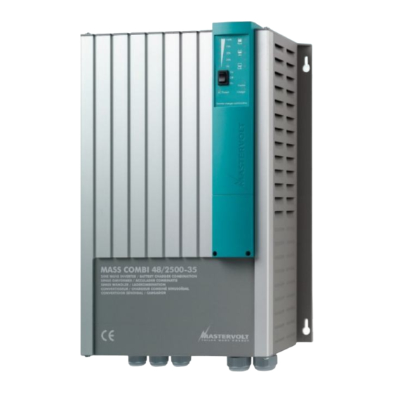
MASS COMBI
12/2500-100; 24/2500-60; 48/2500-35; 48/5000-70
SINE WAVE INVERTER/CHARGER COMBINATION
MASTERVOLT
Snijdersbergweg 93,
1105 AN Amsterdam
The Netherlands
Tel.: +31-20-3422100
Fax.: +31-20-6971006
www.mastervolt.com
WITH GENERATOR / MAINS SUPPORT
ENGLISH:
NEDERLANDS:
DEUTSCH:
FRANÇAIS:
CASTELLANO:
ITALIANO:
Copyright © 2010 Mastervolt , v 2.2 May 2010
PAGE 1
PAGINA 49
SEITE 97
PAGINA 145
PÁGINA 193
PÁGINA 241
Advertisement
Table of Contents

Related Manuals for Mastervolt MASS COMBI 12/2500-100


Summary of Contents for Mastervolt MASS COMBI 12/2500-100
- Page 1 ENGLISH: PAGE 1 MASTERVOLT NEDERLANDS: PAGINA 49 Snijdersbergweg 93, DEUTSCH: SEITE 97 1105 AN Amsterdam FRANÇAIS: PAGINA 145 The Netherlands CASTELLANO: PÁGINA 193 Tel.: +31-20-3422100 ITALIANO: PÁGINA 241 Fax.: +31-20-6971006 www.mastervolt.com Copyright © 2010 Mastervolt , v 2.2 May 2010...
-
Page 2: Table Of Contents
4.3.1 Transfer switch overload protection....................15 4.3.2 Output overload or short circuit ....................... 16 4.3.3 Overheating............................. 16 4.3.4 Under and over voltage ........................16 Maintenance..............................16 Problem solving..............................16 May 2010 / Mass Combi 12/2500-100; 24/2500-60; 48/2500-35; 48/5000-70 / EN... - Page 3 Software version............................... 41 TECHNICAL DATA................................ 42 10.1 Specifications inverter ............................42 10.2 Specifications charger ............................43 10.3 Miscellaneous..............................44 10.4 Characteristics..............................45 ORDERING INFORMATION............................47 EC DECLARATION OF CONFORMITY ........................48 EN / Mass Combi 12/2500-100; 24/2500-60; 48/2500-35; 48/5000-70 / May 2010...
-
Page 4: General Information
DIP-switches (see chapter 6) which are Mass Combi 48/2500-35 / 230V 36042505 used for making user settings. Mass Combi 48/5000-70 / 230V 36045005 For other models see other manuals available on our website: www.mastervolt.com May 2010 / Mass Combi 12/2500-100; 24/2500-60; 48/2500-35; 48/5000-70 / EN... -
Page 5: Safety Guidelines And Measures
• Check the wiring and connections at least once a year. Defects such as loose connections, burned cables etc. must be corrected immediately. EN / Mass Combi 12/2500-100; 24/2500-60; 48/2500-35; 48/5000-70 / May 2010... -
Page 6: Warning Regarding Life Support Applications
Avoid short circuiting batteries, as this may result in explosion and fire hazard. Installation of the batteries and adjustments of the Mass Combi should only be undertaken by authorised personnel! May 2010 / Mass Combi 12/2500-100; 24/2500-60; 48/2500-35; 48/5000-70 / EN... -
Page 7: How It Works
The three-step Plus charge system is also safe for all the connected equipment. See also section 10.4 for detailed characteristics of the three step Plus charge system. EN / Mass Combi 12/2500-100; 24/2500-60; 48/2500-35; 48/5000-70 / May 2010... -
Page 8: Temperature Compensated Charging
The energy saving from your batteries is approximately 10%. For detailed specifications see section 10.1 “DC no load power consumption” Table 1: Mass Combi energy saving modes May 2010 / Mass Combi 12/2500-100; 24/2500-60; 48/2500-35; 48/5000-70 / EN... -
Page 9: Operation Modes
AC OUTPUT AC INPUT “SHORT BREAK” AC OUTPUT “SHORT BREAK” AC INPUT Max. 6A-AC POWER Approx. SHARING 30A-DC CONTROL @12V BATTERIES Figure 6: Power sharing Figure 5: BATTERIES Charger mode EN / Mass Combi 12/2500-100; 24/2500-60; 48/2500-35; 48/5000-70 / May 2010... -
Page 10: Generator / Mains Support Function (Selectable)
For safety reasons the transfer relay is immediately switched off when incoming AC power fails in operation so that there will never be a high voltage on the shore cable inlet when it is not connected. May 2010 / Mass Combi 12/2500-100; 24/2500-60; 48/2500-35; 48/5000-70 / EN... -
Page 11: Power Support Function (Selectable)
AC, while the SHORT BREAK incoming AC. output is connected to the output of the inverter. Table 6: Overview of the AC operationmodes * see chapter 6 for adjustment of the DIP-switches EN / Mass Combi 12/2500-100; 24/2500-60; 48/2500-35; 48/5000-70 / May 2010... -
Page 12: Parallel Operation
Mass Combi. However, with this remote panel you have the convenience to operate the Mass Figure 10: BATTERIES Combi remotely. See chapter 11 for ordering information) Parallel operation May 2010 / Mass Combi 12/2500-100; 24/2500-60; 48/2500-35; 48/5000-70 / EN... -
Page 13: Remote Panel Apc
A protective back box, easy to install, is included as standard for protecting the electronic components. This panel suitable MasterVision, Mastervolt’s modular switchboard system. EN / Mass Combi 12/2500-100; 24/2500-60; 48/2500-35; 48/5000-70 / May 2010... -
Page 14: Operation
4.2.1 Switching on charger regulation will all function automatically. The Mass Combi can be activated by switching the main switch to the “ON” position. May 2010 / Mass Combi 12/2500-100; 24/2500-60; 48/2500-35; 48/5000-70 / EN... -
Page 15: Switching Off
Switch on the Mass Combi. (see section 4.2) CAUTION! The Mass Combi is not protected against reversing polarity of the DC-input, AC voltage on the DC-input and serious over voltage (>265VAC) on the AC-input or AC-outputs. EN / Mass Combi 12/2500-100; 24/2500-60; 48/2500-35; 48/5000-70 / May 2010... -
Page 16: Output Overload Or Short Circuit
The DC-input of the Mass Combi is also, within limits, protected against over under voltage. specifications in section 10.1. The Mass Combi switches off if the DC-input voltage is out of range. May 2010 / Mass Combi 12/2500-100; 24/2500-60; 48/2500-35; 48/5000-70 / EN... -
Page 17: Installation
Maximum rating of the AC compartment as the batteries. input fuse • Do not install the Mass Combi straight above the All models batteries because of possible corrosive sulphur fumes EN / Mass Combi 12/2500-100; 24/2500-60; 48/2500-35; 48/5000-70 / May 2010... -
Page 18: Dc Wiring
Mastervolt distributor or Customer Service Representative. or acceptable. Therefore the automatic connection between the neutral conductor (N) and earth (PE / GND) is disabled by default To enable this automatic connection, see section 6.1.5 May 2010 / Mass Combi 12/2500-100; 24/2500-60; 48/2500-35; 48/5000-70 / EN... -
Page 19: Things You Need
Tools to fix the screws / bolts (Ø 6mm) with plugs to mount the cabinets to a surface • Philips screw driver to open the connection area of the Mass Combi EN / Mass Combi 12/2500-100; 24/2500-60; 48/2500-35; 48/5000-70 / May 2010... -
Page 20: Removal Of The Front Panel
The front panel may never be removed while the Mass Combi is still connected to a power source! Figure 20: Modular communication cable, 8 pole, cross wired. For communication between two Mass Combi’s (parallel operation) May 2010 / Mass Combi 12/2500-100; 24/2500-60; 48/2500-35; 48/5000-70 / EN... -
Page 21: Overview Connection Compartment
(2x) Thermal fuse Negative battery AC output terminal POWER AC output Cooling fan (2x) SHORT BREAK Positive battery terminal Mass Combi model 48/5000-70 Figure 22: Overview connection compartment EN / Mass Combi 12/2500-100; 24/2500-60; 48/2500-35; 48/5000-70 / May 2010... - Page 22 Mass Combi 5000: 279 [11.0] 156 [6.1] 300 [11.8] [0.35] [0.35] R3.25 [R0.13] R6.5 [R0.26] Figure 24: Dimensions in mm [inch] of the Mass Combi 12/2500-100, 24/2500-60, 48/2500-35 and 48/5000-70 May 2010 / Mass Combi 12/2500-100; 24/2500-60; 48/2500-35; 48/5000-70 / EN...
-
Page 23: Mounting Of The Cabinet
Continue with section 5.8.1 for wiring instructions of one Mass Combi in stand alone operation or section 5.8.2 for wiring instructions of two Mass Combi’s in parallel operation. EN / Mass Combi 12/2500-100; 24/2500-60; 48/2500-35; 48/5000-70 / May 2010... - Page 24 This schematic is to illustrate the general placement of the Mass Combi in a circuit. It is not meant to provide detailed wiring instructions for any particular electrical installation. Figure 27: installation drawing for one Mass Combi (stand-alone operation) May 2010 / Mass Combi 12/2500-100; 24/2500-60; 48/2500-35; 48/5000-70 / EN...
-
Page 25: Wiring Instructions For One Mass Combi (Stand Alone Operation)
. Attach the temperature sensor to the battery and run the cable into the Mass Combi. Continue with section 5.8.3 Link the RJ12 connector to the “TEMP.SENS”- connector (Data Bus Connections). EN / Mass Combi 12/2500-100; 24/2500-60; 48/2500-35; 48/5000-70 / May 2010... - Page 26 This schematic is to illustrate the general placement of the Mass Combi in a circuit. It is not meant to provide detailed wiring instructions for any particular electrical installation. NOTE: See also section 6.1.1 for DIP-switch settings Figure 28: installation drawing for two Mass Combi’s (parallel operation). See also figure 29 May 2010 / Mass Combi 12/2500-100; 24/2500-60; 48/2500-35; 48/5000-70 / EN...
-
Page 27: Wiring Instructions For Two Mass Combi's (Parallel Operation)
DC-distribution and each Mass Combi. Connect the red cable to the plus (+) connection, the black cable to Continue with section 5.8.3 the minus (–) connection. Do not install the DC-fuses EN / Mass Combi 12/2500-100; 24/2500-60; 48/2500-35; 48/5000-70 / May 2010... -
Page 28: Alarm Contacts
4 Not used Figure 30: alarm contacts The alarm contact is switched to “Normally Open” in case of an alarm situation, see section 3.6. Maximum switching current: 1 Amp. May 2010 / Mass Combi 12/2500-100; 24/2500-60; 48/2500-35; 48/5000-70 / EN... -
Page 29: Settings
SW1= ON) then its settings SW6 to SW7 of DIP switch A are denied. 6.1.2 Output frequency inverter 230V Models DIP switch A If you want… to set the output frequency to 50 Hz to set the output frequency to 60Hz EN / Mass Combi 12/2500-100; 24/2500-60; 48/2500-35; 48/5000-70 / May 2010... -
Page 30: Energy Saving Mode
Economy 208V. The output voltage will drop to 208V as long as the connected load stays below 250VA. Note: The power saving modes “Idle 40VA” or “Idle 150VA” can only be selected with a Mass Combi 12/2500-100, Mass Combi 24/2500-60 or the Mass Combi 48/2500-35 operating as stand-alone unit. These modes are not available with a Mass Combi 48/5000-70 or two Mass Combi’s in parallel operation. -
Page 31: Dip Switch B
To set the frequency window for the incoming AC power at 35Hz < f < 65Hz CAUTION! Adjustment of the frequency window at a too low level may cause damage to the connected AC-load. Refer to the AC-input specifications of the connected loads. EN / Mass Combi 12/2500-100; 24/2500-60; 48/2500-35; 48/5000-70 / May 2010... -
Page 32: Combi/Inverter Control
An equalizing charge can be necessary after very deep discharges and/or inadequate charges. This has to be carried out according to the specifications of the manufacturer of the batteries. If you want… DIP switch B To start the equalize mode Off-On-Off pulse May 2010 / Mass Combi 12/2500-100; 24/2500-60; 48/2500-35; 48/5000-70 / EN... -
Page 33: Start-Up After Installation
Now the Mass Combi is ready for operation. EN / Mass Combi 12/2500-100; 24/2500-60; 48/2500-35; 48/5000-70 / May 2010... -
Page 34: Masterbus
MasterBus by means of your PC or notebook. Refer to the “Frequently asked questions about MasterBus” in the Mastervolt Powerbook.for more details about Masterbus, Terminating Terminating device device May 2010 / Mass Combi 12/2500-100; 24/2500-60; 48/2500-35; 48/5000-70 / EN... -
Page 35: Masterbus: Monitoring And Configuration Of The Mass Combi
Inverter mode: Displays the AC power as a percentage of the nominal inverter power Charger Charge state Status of the battery charger (“Bulk”, “Absorption” or “Float” (read only) EN / Mass Combi 12/2500-100; 24/2500-60; 48/2500-35; 48/5000-70 / May 2010... -
Page 36: Configuration
Alarm DC low off (see section 3.6) 11.00/22.00/44.00V 8-16.00/16-32.00/32- 64.00V DC Alrm delay Alarm delay time (see section 3.6) 30 sec 1-255 sec All error Alarm function will be triggered by all errors Off, On May 2010 / Mass Combi 12/2500-100; 24/2500-60; 48/2500-35; 48/5000-70 / EN... -
Page 37: List Of List Of Events Sources
MasterBus. Event source Description Disabled (no event programmed) Charging The Mass Combi is in Charge mode Inverting The Mass Combi is in Inverter mode EN / Mass Combi 12/2500-100; 24/2500-60; 48/2500-35; 48/5000-70 / May 2010... -
Page 38: List Of List Of Event Commands
If the Event Source switches to “On”, the Operation mode of the Mass Combi will be set to “Auto”; If the Event Source switches to “Off”, the Operation mode of the Mass Combi will be set to “Charger”. May 2010 / Mass Combi 12/2500-100; 24/2500-60; 48/2500-35; 48/5000-70 / EN... -
Page 39: Trouble Shooting
3 = solid yellow DC voltage error. The battery Check the batteries. 8 = solid red voltage is too high or too low. EN / Mass Combi 12/2500-100; 24/2500-60; 48/2500-35; 48/5000-70 / May 2010... - Page 40 If you cannot solve a problem with the aid of this table, contact your local Mastervolt Service Centre. See www.mastervolt.com. Make sure you have the following information present if you have to contact your local Mastervolt Service Center to solve a problem: Article and serial number (See section 1.6)
-
Page 41: Software Version
Flashes 0 times Flashes 2 times Flashes 5 times 2 . 0 Software version Software version: 1 . 3 Figure 33: Representation of the software versions of the Mass Combi EN / Mass Combi 12/2500-100; 24/2500-60; 48/2500-35; 48/5000-70 / May 2010... -
Page 42: Technical Data
≥90% Load power factor range All power factors allowed Over temperature, overload, short circuit, AC on output, high battery, low Protections battery. * adjustable by means of MasterAdjust software May 2010 / Mass Combi 12/2500-100; 24/2500-60; 48/2500-35; 48/5000-70 / EN... -
Page 43: Specifications Charger
13.25V / 26.50V / 53V 13.80V / 27.20V / 54,4 13.25V / 26.50V / 53 * adjustable by means of MasterAdjust software. ** traction max ABS/BULK time + 120min. EN / Mass Combi 12/2500-100; 24/2500-60; 48/2500-35; 48/5000-70 / May 2010... -
Page 44: Miscellaneous
Mix of conventional and forced air cooling, by DC fans with variable speed. The fan does operate on a temperature current control related PWM Fan operation variable speed control. DC maintenance free fan. May 2010 / Mass Combi 12/2500-100; 24/2500-60; 48/2500-35; 48/5000-70 / EN... -
Page 45: Characteristics
4 hr timer: 8 hr every 336 hr bulk timer = current Figure 35: Charge characteristic of the three-step Plus charging method for the 12V combi (@ 25°C / 77°F) EN / Mass Combi 12/2500-100; 24/2500-60; 48/2500-35; 48/5000-70 / May 2010... - Page 46 Battery Charging is not allowed above +55°C and below –20°C 12 Volt system: –30mV/°C 24 Volt system: –60mV/°C 48 Volt system: –120mV/°C Figure 37: Temperature compensation characteristic (charge voltage versus temperature) May 2010 / Mass Combi 12/2500-100; 24/2500-60; 48/2500-35; 48/5000-70 / EN...
-
Page 47: Ordering Information
Continuous rating: 250A, peak current: 500A * These parts are standard included with the delivery of the Mass Combi 12/2500-100, 24/2500-60, 48/2500-35 and 48/5000- Mastervolt can offer a wide range of products for your electrical installation, including automatic AC transfer switches, remote control panels and DC distribution kits. -
Page 48: Ec Declaration Of Conformity
Address Snijdersbergweg 93 1105 AN Amsterdam The Netherlands Herewith declares that: Product: 36012505 Mass Combi 12/2500-100 / 230V 36022505 Mass Combi 24/2500-60 / 230V 36042505 Mass Combi 48/2500-35 / 230V 36045005 Mass Combi 48/5000-70 / 230V Is in conformity with the following provisions of the EC •...
Need help?
Do you have a question about the MASS COMBI 12/2500-100 and is the answer not in the manual?
Questions and answers