Table of Contents
Advertisement
Quick Links
Advertisement
Table of Contents

Related Manuals for Peavey PVXp 10 DSP


Summary of Contents for Peavey PVXp 10 DSP
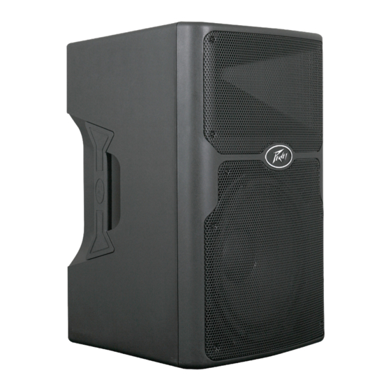
- Page 1 PVXp 10 DSP ™ Powered Speaker System Operating Manual www.peavey.com...
- Page 2 (2) I’utilisateur de I’appareil doit accepter tout brouillage radioélectrique subi, même si le brouillage est susceptible d’en compromettre le fonctionnement. Warning: Changes or modifications to the equipment not approved by Peavey Electronics Corp. can void the user’s authority to use the equipment.
- Page 3 ENGLISH Introduction Thank you for purchasing the Peavey PVXp™ 10 DSP powered speaker system. The PVXp™ 10 DSP features a reliable bi-amped power section that provides a total of 510 Watts of peak available dynamic power. With that much available power, speaker protection is critical. Advanced digital signal compression prevents audible overload, protecting the speakers from harmful distortion at high output levels.
- Page 4 A typical signal source for the line-level inputs of the Peavey PVXp™10 DSP would be a sound reinforcement mixing console (mixer) or the output from a CD player, MP3 player or tape deck. A dynamic microphone can be connected directly via the XLR input and used when the Mic/Line switch in placed into the “Mic”...
-
Page 5: On/Off Switch
Under normal (not tripped) conditions, the center button is relatively flat. If the unit continues to trip the breaker, or trips it immediately after being reset, do not keep resetting it, the system should be taken to a qualified Peavey Service Center for repair. IEC POWER CORD CONNECTION (3) This receptacle is for the IEC line cord (supplied) that provides AC power to the unit. -
Page 6: Mic/Line Switch
UPPER REAR PANEL INPUT (4) The line-level input is of the medium impedance balanced type. The jack is a combo female XLR and 1/4" TRS connector. Sensitivity of this input is 0.48 volts for full output, when the MIC/LINE switch (6) is in the LINE position. - Page 7 OPERATING INSTRUCTIONS LCD Display (8) Provides a menu read-out manipulated and activated by the Push-To-Select button (9) Push-To-Select button (9) Rotary knob that allows the user to select and choose menu options on the LCD display screen (8). Pushing the button in till it detents makes a menu choice.
- Page 8 Use of the PVXp™10 DSP with a Speaker Stand The PVXp™ 10 DSP has a stand mount cup molded-in so that the system can be stand mounted on a standard 1 3/8” (36mm) diameter stand pole. When using stands or poles, be sure to follow these precautions: Check the stand or pole specs to make sure that it can support the weight of the PVXp™...
- Page 9 If the mixing board indicates clipping of its output signals, then all of the PVXp™ 10 DSP power capability is not being utilized cleanly. Clipping the signal before it gets to the PVXp™ 10 DSP is not optimal. Reduce the mixer output level and turn up the Level control on the PVXp™...
-
Page 10: Troubleshooting
Rotate the “Push-to-Select” knob to choose the amount of boost or cut in 1dB increments from +6 dB down to - 6dB. these tone changes occur on top of an existing factory EQ preset. To exit the treble menu, press the “Push-to-Select”, the cursor will then shift back to the “function” side of the LCD. - Page 11 If so, turn off the PVXp™ 10 DSP and let it cool for a sufficient amount of time. If there is still no output, contact your authorized Peavey dealer or the Peavey International Service Center. Hum or Buzz If the PVXp™...
- Page 12 122 dB with music as a source, when measured at a distance of 1M and driven to full output capacity. The system shall utilize a Peavey Pro 10 10” heavy-duty woofer and a Peavey® RX™10N dynamic compression driver. The nominal radiation pattern shall be 100° in the horizontal plane, and 60° in the vertical plane.
- Page 13 All associated rigging is the responsibility of others. This Peavey loudspeaker should be suspended overhead only in accordance with the procedures and limitations specified in the User’s Manual and possible manual update notices. This system should be suspended with certi- fied rigging hardware by an authorized rigging professional and in compliance with local, state or provincial, and federal or national suspension ordinances.
- Page 14 Group C A set of four M8 inserts on the top, designed to be used with the Peavey® Versamount™ 70+ mounting bracket. Group D A set of four M8 inserts on the bottom, designed to be used with the Peavey Versamount 70+ mounting brack- For Group A and B, always use both inserts as a pair;...
-
Page 15: Specifications
Additional mounting points are a set of four M8 inserts on the top, and a set of four on the bottom, which use the Peavey Versamount 70+ mounting bracket. Four rubber feet provide vibration free floor or stage use, and a molded-in stand mounting cup is on the bottom. - Page 16 THD and IM: Typically less than 0.5 % Damping Factor: Greater than 100 @ 1000 Hz, 8 Ohms Power requirements of Peavey PVXp 10 DSP System: Nominal 100 Watts, 100-240 VAC 50-60 Hz *specifications and features subject to change without notice.
- Page 18 Warranty registration and information for U.S. customers available online at www.peavey.com/warranty or use the QR tag below Features and speci cations subject to change without notice. Peavey Electronics Corporation 5022 Hartley Peavey Drive Meridian, MS 39305 (601) 483-5365 FAX (601) 486-1278 Logo referenced in Directive 2002/96/EC Annex IV (OJ(L)37/38,13.02.03 and defined in EN 50419: 2005...
Need help?
Do you have a question about the PVXp 10 DSP and is the answer not in the manual?
Questions and answers