SKF LINCOLN P 212 Installation Instructions Manual
Hide thumbs
Also See for LINCOLN P 212:
- Assembly instructions manual (48 pages) ,
- Assembly instructions manual (36 pages)

Related Manuals for SKF LINCOLN P 212


Summary of Contents for SKF LINCOLN P 212
- Page 1 Installation Instructions P 212 Pump P 212 810-53492-1 Page 1 of 40 Rev.: 007 2021/04/13...
- Page 2 Declaration of Incorporation (Following Machinery Directive 2006/42/EC, Appendix II, Part 1 B) The Manufacturer SKF Lubrication Systems Germany GmbH, Heinrich-Hertz-Str. 2-8, D - 69190 Walldorf Hereby declares that the partly completed machinery Designation: Multi-line pump for supplying lubricants within a centralized lubrication system...
-
Page 3: Table Of Contents
Installation Instructions P 212 Pump Declaration of Incorporation Contents Guidelines ......................6 Warnings ....................... 6 Illustrations ....................6 Copyright ....................... 6 Abbreviations ....................7 Manufacturer and Service addresses ............7 Warranty ......................7 Disclaimer ...................... 7 Safety information ..................... 8 2.1. - Page 4 Installation Instructions P 212 Pump Inspection for correct use ................. 15 2.25. Briefing of external technicians ..............16 2.26. Provision of personal protective equipment ..........16 2.27. Training courses ..................16 2.28. Inspection of the delivery ................16 2.29. Returns ..................... 16 2.30.
- Page 5 Installation Instructions P 212 Pump Installation and commissioning ..............27 7.1. Important note on the installation of the pump elements ......27 7.2. Assembly of the pump elements ..............28 7.3. Adjustment of the pump elements ............... 29 7.4. Filling the reservoir ..................30 7.5.
-
Page 6: Guidelines
The used refer to a specific product. In the case of other products or product variants they may have a schematic character only. The basic functions, however, do not change. Copyright © SKF. All rights reserved. 810-53492-1 Page 6 of 40 Rev.: 007... -
Page 7: Abbreviations
Manufacturer and Service addresses Manufacturer Customer Service SKF Lubrication Systems SKF Lubrication Systems Germany GmbH Germany GmbH Central Customer Service Dept. Heinrich-Hertz-Str. 2-8 P.O. Box 1263 D - 69190 Walldorf D - 69183 Walldorf Warranty The instructions make no statement regarding warranty. -
Page 8: Emergency Stopping Of Pump
Installation Instructions P 212 Pump 2. Safety information Safety information is to be read and observed by any persons entrusted with works on the pump or by those persons who supervise or instruct the before-mentioned group of persons. It is prohibited to commission or operate the pump prior to reading the Instructions. -
Page 9: Conversions/ Modifications
Installation Instructions P 212 Pump 2.6. Conversions/ modifications Unauthorized conversions or modifications may result in unforeseeable impacts on safety. Therefore, any unauthorized reconstructions or changes are expressly prohibited. 2.7. Inspections The following inspections were carried out prior to delivery: Electrical inspections following EN 60204-1. •... -
Page 10: Energies
Installation Instructions P 212 Pump 2.12. Energies Electricity • Temperature (hot/cold surfaces) • Position energy (raised components) • Parts subject to (operating) pressure • Parts subject to spring tension • 2.13. Lubricants Greases • Oils • 2.14. Existing residual risks Residual risk Remedy Transport life cycle... - Page 11 Installation Instructions P 212 Pump Residual risk Remedy Installation life cycle People falling due to contamination of floors Take care when filling. Bind / remove spilled with spilled lubricant. lubricant immediately with a suitable agent. Observe the legal / company regulations on dealing with oils / greases and contaminated parts.
-
Page 12: Persons Authorized To Operate The Pump
Installation Instructions P 212 Pump 2.15. Persons authorized to operate the pump Operator A person who is qualified by training and experience to carry out the functions and activities related to normal operation, including the avoidance of possible hazards that may arise during machine operation. Person qualified for maintenance and repair works A professionally trained and experienced person that is capable of recognizing risks and possible hazards when carrying out installation, maintenance, or repair... -
Page 13: Transport, Installation, Maintenance, Repairs, Servicing
Installation Instructions P 212 Pump 2.19. Transport, installation, maintenance, repairs, servicing All relevant people, (e.g. operating personnel, superiors) are to be • informed prior to starting the work about its execution. Observe the company precautionary measures / working instructions. If protective and safety equipment must be dismantled, it must be •... -
Page 14: Initial Commissioning, Daily Start-Up
Installation Instructions P 212 Pump Only undertake drilling at non-critical, non-supporting parts. Use any • available boreholes. Do not damage lines and cables when drilling. Observe possible abrasion points. Protect the parts accordingly. • Other aggregates of the machine / vehicle must not be adversely affected •... -
Page 15: Cleaning
Installation Instructions P 212 Pump 2.21. Cleaning Risk of fire and explosion when using flammable cleaning agents. Only use • non-flammable cleaning agents suitable for the purpose. Do not use aggressive cleaning agents. • Do not use steam jet or high-pressure cleaners. Electrical components •... -
Page 16: Briefing Of External Technicians
2.28. Training courses To provide a maximum of safety and economic viability, SKF carries out detailed training courses. It is recommended that the training courses are attended. Please contact SKF Customer Services for information. -
Page 17: Selection Of Lubricants
Should you have little or no experience with the selection of lubricants for centralized lubrication systems, please contact SKF. You will avoid possible costly downtimes through damage to your machine respectively system or damage to the centralized lubrication system. -
Page 18: Ageing Of Lubricants
To avoid this, always use lubricants which have been tested by SKF. Please contact the Service Department for an overview of lubricants tested by SKF. 3.3. Ageing of lubricants After a prolonged machine downtime, the lubricant must be inspected prior to recommissioning as to whether it is still suitable for use due to chemical / physical ageing. -
Page 19: Operating Temperature
Installation Instructions P 212 Pump 4. Technical data 4.1. Operating temperature min. max. -20 °C +70 °C Make sure to use a lubricant that suits the actual ambient temperature (e. g. lubricant for low-temperature applications). 4.2. Operating pressure Max. 350 bar All system parts must be designed for the maximum operating pressure. -
Page 20: Ip-Protection Class
Installation Instructions P 212 Pump 4.8. IP-protection class Motor: For IP protection class, see motor type plate respectively chapter “Technical dataof the motors”. Ultrasonic sensor: IP 65 4.9. Tightening torques Component Tightening torques Pump element to housing Counternut spindle to pump element Closure screw to housing 35 +2 4.10. -
Page 21: Flow Rate
Installation Instructions P 212 Pump 4.14. Flow rate The flow rate is infinitely variable as follows: KR 07 30 % to 100 % KR 12 40 % to 100 % The indications stated in the flow rate diagrams apply to Fuchs Renocal FN 745/95 NLGI 2 at + 20°... -
Page 22: Motor
Installation Instructions P 212 Pump 4.15. Motor Type / designation T 80A/4 Type of protection IP 55 Cos. φ 0.76 Insulation class Nominal current I 1.6 A (400V) Mode of operation Nominal capacity 0.55/0.64 Speed 1400/1680 min Frequency 50/60 Construction type Size Flange 120 mm... -
Page 23: High-Level Signal / Low-Level Signal / Minimum Switching Distance
Installation Instructions P 212 Pump 5. Technical data of the ultrasonic sensor 5.1. High-level signal / low-level signal / minimum switching distance Reservoir Switch point: high-level signal A Switch point: low-level signal B XYBU approx. approx. 420 mm The minimum distance between the lubricant and the ultrasonic sensor totals 60 mm. If this distance is underrun, incorrect measurement results may occur due to undefined ultrasonic sensor switching conditions. - Page 24 Installation Instructions P 212 Pump 810-53492-1 Page 24 of 40 Rev.: 007 2021/04/13...
-
Page 25: Brief Description Of The Pump
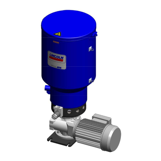
Installation Instructions P 212 Pump 6. Brief description of the pump DANGER Electric shock Disconnect the pump from the mains prior to all works on electrical parts, Pump 212 consists of the following main components: (1) Ultrasonic sensor (2) Reservoir with stirring paddle (3) Filling connection (4) Pump elements (1-12) (5) Pump housing... - Page 26 Installation Instructions P 212 Pump Working method: The gear (6) reduces the motor speed (7) to the necessary speed of the eccentric shaft (8). The eccentric shaft (8) drives the pump elements (4) and the stirring paddle. The stirring paddle homogenizes and ventilates the lubricant and pushes it in the direction of the suction boreholes of the pump elements (4).
-
Page 27: Important Note On The Installation Of The Pump Elements
Installation Instructions P 212 Pump 7. Installation and commissioning 7.1. Important note on the installation of the pump elements Pump elements are factory-set to minimum flow rate to improve the suction behaviour (minimum space of air in the pump element). After commissioning, the pump elements must be set to the required flow rate. -
Page 28: Assembly Of The Pump Elements
Installation Instructions P 212 Pump 7.2. Assembly of the pump elements ATTENTION Damages to the pump are possible. Make sure that each pump element is seated correctly in the notch of the catch ring. Remove closure screw. ... -
Page 29: Adjustment Of The Pump Elements
Installation Instructions P 212 Pump 7.3. Adjustment of the pump elements NOTE: The output of the pump elements can be modified also during operation. Loosen counternut (1). To adjust the flow rate, turn the spindle (2). = lower flow rate ... -
Page 30: Filling The Reservoir
Installation Instructions P 212 Pump 7.4. Filling the reservoir WARNING Risk of hand injuries caused by the stirring paddle Fill lubricant via the lid only when the pump is not moving. Never reach into the reservoir while the pump is running. ATTENTION Risk of central lubrication system faults •... -
Page 31: Inadvertent Filling With Incorrect Lubricant
Installation Instructions P 212 Pump 7.5. Inadvertent filling with incorrect lubricant Should incorrect lubricant have been filled, please proceed as follows. Switch off the pump and secure it against being switched on. Remove lubricant. Clean the reservoir, pump housing and, if applicable, the tubing system. ... -
Page 32: Activation Of The Pump
Installation Instructions P 212 Pump The following points must be inspected prior to initial commissioning: Electrics: Electrical connections carried out correctly. • Cable entries sealed correctly. • The voltage and frequency of the power network correspond to the • information on the type identification plate of the motor. Monitoring devices and additional equipment (e.g. -
Page 33: Daily Start-Up
Installation Instructions P 212 Pump 8. Standard operation 8.1. Daily start-up Below find the activities to be carried out in case of standard operation. 8.2. Inspections Regarding “Inspections prior to initial commissioning” the operator has to define suitable inspection intervals depending on the actual operating conditions. 8.3. -
Page 34: Pump Maintenance
Installation Instructions P 212 Pump 9. Maintenance DANGER Electric shock Disconnect the pump from the mains electrically prior to all work on electrical parts. 9.1. Pump maintenance The pump is mainly maintenance-free. However, the following parts should be inspected and, if necessary, replaced by new parts at regular intervals: Pressure relief valves •... -
Page 35: Troubleshooting
Installation Instructions P 212 Pump Troubleshooting Pump motor does not run Possible cause Observation Remedy Fault with superior machine / Stirring paddle does not Check power lines with external PLC controller / rotate; no pump sound; control See fault analysis of machine motor circuit breaker released pins do not move Determine cause... -
Page 36: Spare Parts
Installation Instructions P 212 Pump Spare parts 11.1. Pump P 212 810-53492-1 Page 36 of 40 Rev.: 007 2021/04/13... - Page 37 Installation Instructions P 212 Pump Item Name Qty. Part no. Fastening plate 460-73065-1 Motor 0,55kW with gear 67:1 245-13996-1 Closure screw 1-12 303-17431-1 Housing P212 460-73066-1 Sealing ring for closure screw 1-12 306-17814-1 O-ring 186 x 3,5 219-12226-8 Radial sealing ring 30x50x7 220-12231-4 Slide washer 460-73062-1...
-
Page 38: Pump Element Kr 12
Installation Instructions P 212 Pump 11.2. Pump element KR 12 Item Name Qty. Part no. Pump element KR 12 assy., including outlet stud with check valve 660-77619-1 assy. and sealing ring Outlet stud with check valve assy. 560-33838-1 Sealing ring 306-17814-1 11.3. - Page 39 Installation Instructions P 212 Pump Notice 810-53492-1 Page 39 of 40 Rev.: 007 2021/04/13...
- Page 40 Installation Instructions P 212 Pump SKF Lubrication Systems Germany GmbH Walldorf Facilities Heinrich-Hertz-Str. 2-8 DE - 69190 Walldorf Phone: +49 (0) 6227 33-0 Fax: +49 (0) 6227 33-259 E-mail: Lubrication-germany@skf.com www.skf.com/lubrication 810-53492-1 Page 40 of 40 Rev.: 007 2021/04/13...
Need help?
Do you have a question about the LINCOLN P 212 and is the answer not in the manual?
Questions and answers