Table of Contents

Subscribe to Our Youtube Channel
Related Manuals for Toshiba RAV-SM2244DTP-TR


Summary of Contents for Toshiba RAV-SM2244DTP-TR
- Page 1 FILE NO. SVM-16023-4 SERVICE MANUAL AIR-CONDITIONER SPLIT TYPE INDOOR UNIT <DIGITAL INVERTER> Concealed Duct High Static Pressure Type RAV-SM2244DTP-E RAV-SM2804DTP-E RAV-SM2244DTP-TR RAV-SM2804DTP-TR R410A Revised on December, 2018...
-
Page 2: Table Of Contents
CONTENTS Definition of Qualified Installer or Qualified Service Person....... 4 Warning Indications on the Air Conditioner Unit .......... 6 Precaution for Safety ..................7 Refrigerant (R410A) ..................14 1. SPECIFICATION ..................16 2. FAN CHARACTERISTICS ..............19 3. CONSTRUCTION VIEWS (EXTERNAL VIEWS) ........20 4. - Page 3 12. EXPLODED VIEWS AND PARTS LIST ............100 12 - 1. RAV-SM2244DTP-E(TR), RAV-SM2804DTP-E(TR) ........100 12 - 2. Drain pump kit (TCB-DP40DPE) ..............102 12 - 3. Electric Parts ....................103 – 3 –...
-
Page 4: Definition Of Qualified Installer Or Qualified Service Person
• The qualified service person is a person who installs, repairs, maintains, relocates and removes the air conditioners made by Toshiba Carrier Corporation. He or she has been trained to install, repair, maintain, relocate and remove the air conditioners made by Toshiba Carrier Corporation... - Page 5 Definition of Protective Gear When the air conditioner is to be transported, installed, maintained, repaired or removed, wear protective gloves and ‘safety’ work clothing. In addition to such normal protective gear, wear the protective gear described below when undertaking the special work detailed in the table below.
-
Page 6: Warning Indications On The Air Conditioner Unit
Warning Indications on the Air Conditioner Unit [Confirmation of warning label on the main unit] Confirm that labels are indicated on the specified positions If removing the label during parts replace, stick it as the original. Warning indication Description WARNING WARNING ELECTRICAL SHOCK HAZARD ELECTRICAL SHOCK HAZARD... -
Page 7: Precaution For Safety
PRECAUTIONS FOR SAFETY The manufacturer shall not assume any liability for the damage caused by not observing the description of this manual. DANGER Before carrying out the installation, maintenance, repair or removal work, be sure to set the circuit breaker for both the indoor and outdoor units to the OFF position. Otherwise, electric shocks may result. - Page 8 WARNIG Before starting to repair the air conditioner, read carefully through the Service Manual, and repair the air conditioner by following its instructions. Only qualified service person (*1) is allowed to repair the air conditioner. Repair of the air conditioner by unqualified person may give rise to a fire, electric shocks, injury, water leaks and / or other problems.
- Page 9 Do not modify the products.Do not also disassemble or modify the parts. It may cause a fire, electric shock or injury. Prohibition of modification. When any of the electrical parts are to be replaced, ensure that the replacement parts satisfy the specifications given in the Service Manual (or use the parts contained on the parts list in the Service Manual).
- Page 10 After repair work, surely assemble the disassembled parts, and connect and lead the removed wires as before. Perform the work so that the cabinet or panel does not catch the inner wires. If incorrect assembly or incorrect wire connection was done, a disaster such as a leak or fire is caused Assembly / at user’s side.
- Page 11 When the service panel of the outdoor unit is to be opened in order for the compressor or the area around this part to be repaired immediately after the air conditioner has been shut down, set the circuit breaker to the OFF position, and then wait at least 10 minutes before opening the service panel. If you fail to heed this warning, you will run the risk of burning yourself because the compressor pipes and other parts will be very hot to the touch.
- Page 12 Declaration of Conformity TOSHIBA CARRIER (THAILAND) CO., LTD. Manufacturer: 144 / 9 Moo 5, Bangkadi Industrial Park, Tivanon Road, Tambol Bangkadi, Amphur Muang, Pathumthani 12000, Thailand Authorized Representative / Nick Ball TCF holder: Toshiba EMEA Engineering Director Toshiba Carrier UK Ltd.
- Page 13 Specifications Sound pressure level (dBA) Weight (kg) Model Main unit Cooling Heating RAV-SM2244DTP-E RAV-SM2804DTP-E RAV-SM2244DTP-TR RAV-SM2804DTP-TR – 13 –...
-
Page 14: Refrigerant (R410A)
Refrigerant (R410A) This air conditioner adopts a HFC type refrigerant (R410A) which does not deplete the ozone layer. 1. Safety Caution Concerned to refrigerant (R410A) The pressure of R410A is high 1.6 times of that of the former refrigerant (R22). Accompanied with change of refrigerant, the refrigerating oil has been also changed. - Page 15 4. Tools 1. Required Tools for R410A Mixing of different types of oil may cause a trouble such as generation of sludge, clogging of capillary, etc. Accordingly, the tools to be used are classified into the following three types. 1) Tools exclusive for R410A (Those which cannot be used for conventional refrigerant (R22)) 2) Tools exclusive for R410A, but can be also used for conventional refrigerant (R22) 3) Tools commonly used for R410A and for conventional refrigerant (R22) The table below shows the tools exclusive for R410A and their interchangeability.
-
Page 16: Specification
1. SPECIFICATIONS (50Hz) Concealed Duct Static Pressure Type Indoor Unit RAV- SM2244DTP-E / -TR SM2804DTP-E / -TR Model name Outdoor Unit RAV- SM2244AT(Z)(ZG)8-E SM2804AT(Z)(ZG)8-E Cooling capacity …Note 1 (kW) 20.0 23.7 Heating capacity …Note 1 (kW) 22.4 27.0 Electrical Cooling Indoor Unit Power supply 1phase 50Hz 230V(220V-240V) - Page 17 (60Hz) Concealed Duct Static Pressure Type Indoor Unit RAV- SM2244DTP-E SM2804DTP-E Model name Outdoor Unit RAV- SM2244AT7 SM2804AT7 Cooling capacity …Note 1 (kW) 20.0 23.7 Heating capacity …Note 1 (kW) 22.4 27.0 Electrical Cooling Indoor Unit Power supply 1phase 60Hz 220V characteristics Running current 2.93...
- Page 18 (50Hz) Concealed Duct Static Pressure Type for Australia, New zealand Indoor Unit RAV- SM2244DTP-E SM2804DTP-E Model name Outdoor Unit RAV- SM2244AT8-A1 SM2804AT8-A1 Cooling capacity …Note 1 (kW) 16.8 20.0 Heating capacity …Note 1 (kW) 22.4 27.0 Electrical Cooling Indoor Unit Power supply 1phase 50Hz 230V-240V characteristics...
-
Page 19: Fan Characteristics
2. FAN CHARACTERISTICS SM224 type Standard Standard Air Air Flow Flow : : 3800 3800 (m3/h) (m3/h) Standard Standard Air Air Flow Flow : : 3800 3800 (m3/h) (m3/h) 350 ... -
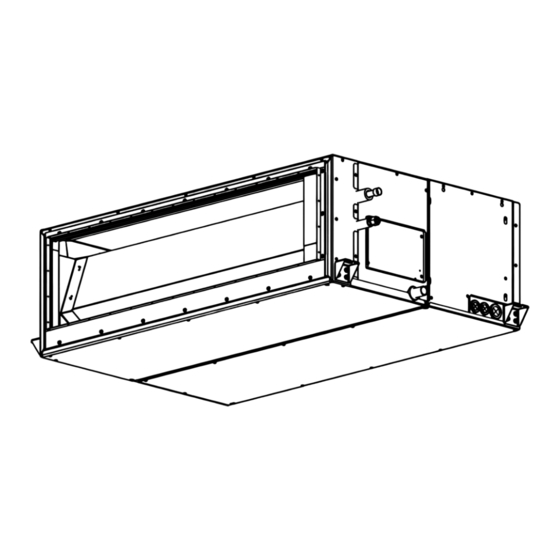
Page 20: Construction Views (External Views)
3. CONSTRUCTION VIEWS (EXTERNAL VIEWS) Unit : mm – 20 –... - Page 21 Duct arrangement Unit : mm <Air outlet> 1296(Outside) 98 100100100100100100100100100100100 98 90 90 90 <Air inlet> 1316 58 200 200 58 1297 Electrical control box – 21 –...
-
Page 22: Wiring Diagram
4. WIRING DIAGRAMS Color Indication RED : Red WHI : White YEL : Yellow BLU : Blue BLK : Black Drain Pump BRW : Brown Kit Attached t° t° t° (Option) CN34 (RED) CN101 CN104 CN102 RY02 (RED) (BLK) (YEL) SW501 CN34 (RED) -
Page 23: Parts Rating
5. PARTS RATING Model RAV- SM224* SM280* KF-340W1000-1 Fan motor Lead wire length:218mm TA sensor ∅6 size lead wire length:1000mm Vinyl tube (Black) TC sensor ∅6 size lead wire length:1000mm Vinyl tube (Red) TCJ sensor PCD-4N230TF-4 Drain pump (option) FS-1A-31-3 Float switch (option) –... -
Page 24: Control Block Diagram
6. CONTROL BLOCK DIAGRAM 6-1. Indoor Controller Block Diagram 6-1-1. In Case of Connection of Wired (Simple) Remote Controller Wired (Simple) header remote controller (Up to 2 units) Schedule timer Display LCD Display Function setup driver Key switch Display LED Function setup DC5V Power... - Page 25 6-1-2. In Case of Connection of Wireless Remote Controller Indoor unit #1 (Header) (Follower) (Follower) Wireless remote controller kit Indoor control P.C. Board Receiving P.C. Board (MCC-1643) DC20V Remote controller Remote controller communication circuit communication circuit Emergent EEPROM Power operation circuit TA sensor DC5V...
- Page 26 6-1-3. Connection of Both Wired (Simple) Remote Controller and Wireless Remote Controller Schedule timer Wired (Simple) header remote controller Display LCD Function setup Display driver Key switch EEPROM Function setup DC5V DC5V Power Display LED Key switch circuit Remote controller Secondary Power communication circuit...
-
Page 27: Control Specifications
6-2. Control Specifications Item Outline of specifications Remarks When power 1) Distinction of outdoor unit supply is reset When the power supply is reset, the outdoors are distin- guished and the control is selected according to the distinguished result. 2) Setting of indoor fan speed and existence of air direction adjustment Based on EEPROM data, select setting of the indoor fan speed. - Page 28 Item Outline of specifications Remarks Room temp. 2) Using the CODE No. 06, the setup temperature in heating Shift of suction control operation can be corrected. temperature in heating (Continued) operation SET DATA Setup temp. +0°C +2°C +4°C +6°C correction Setting at shipment SET DATA Automatic...
- Page 29 Item Outline of specifications Remarks 1) Operation with (HH), (H), (L) or [AUTO] mode is carried Fan speed control HH > H+ > H > L+ > out by the command from the remote controller. L > UL 2) When the fan speed mode [AUTO] is selected, the fan speed varies by the difference between <COOL>...
- Page 30 Item Outline of specifications Remarks Fan speed control 50Pa 83Pa 117Pa 150Pa 183Pa 217Pa 250Pa CODE No. (Continued) [ 5d ] DN : 0001 0002 0004 0000 0005 0003 0006 SW501 (1)-(2) ON-OFF OFF-OFF OFF-ON ON-ON HEAT COOL HEAT COOL HEAT COOL HEAT COOL HEAT COOL HEAT COOL HEAT COOL 3) In heating operation, the fan speed changes to [UL] if thermostat is turned off.
- Page 31 Item Outline of specifications Remarks 1) The cooling operation (including Dry operation) is Freeze preventive control (Low temperature release) performed as follows based on the detected Indoor heat exchanger temperature of T sensor or T sensor. sensor temperature When [J] zone is detected for 6 minutes (Following figure), the commanded frequency of compressor is decreased.
- Page 32 Item Outline of specifications Remarks 1) The heating operation is performed as follows based on the High-temp. detected temperature of T sensor or T sensor. release control • When [M] zone is detected, the commanded frequency is However this control is decreased.
- Page 33 Remarks Item Outline of specifications Frequency Command frequency is <In case of wired remote controller> fixed operation approximately [S7] 1) When pushing [CHK] button for 4 seconds or more, [TEST] is (Test run) displayed on the display screen and the mode enters in Test run mode.
- Page 34 Item Outline of specifications Remarks 1) Setting at the central controller side enables to select Central control mode selection the contents which can be operated on the wired remote controller. 2) Setup contents • In case of TCC-LINK Central remote controller (TCB-SC642TLE2) [Individual]: Operated by wired remote controller...
- Page 35 Item Outline of specifications Remarks DC motor 1) When the fan operation has started, positioning of the stator and the rotor are performed. (Moves slightly with tap sound) 2) The motor operates according to the command from the indoor controller. Notes) •...
-
Page 36: Indoor Print Circuit Design Board
6-3. Indoor Print Circuit Design Board <MCC-1643> – 36 –... - Page 37 6-3-1. Optional connector specifications of Indoor Circuit Design Board – 37 –...
- Page 38 6-3-2. Fan IPDU P.C. Board (MCC-1610) Power relay output CN602 CN602 CN702 UART CN504 communication between CN504 UART CN505 communication CN705 between Fan motor output U-phase Application control kit (TCB-PCUC1E) CN705 CN704 CN505 Fan motor output V-phase CN704 CN703 Fan motor output W-phase CN703 CN511 CN500...
- Page 39 6-3-3. Noise filter (MCC-1551) CN04 (White) CN04 (White) Power supply input Power supply output (Neutral) (Neutral) Line Filter CN03 (Red) CN08 (Blue) CN01 (Red) Power supply output (Live) Power supply output Power supply input (Live) for drain pump kit *option –...
-
Page 40: Troubleshooting
7. TROUBLESHOOTING 7-1. Summary of Troubleshooting <Wired remote controller type> 1. Before troubleshooting 1) Required tools/instruments • screwdrivers, spanners, radio cutting pliers, nippers, push pins for reset switch – • Tester, thermometer, pressure gauge, etc. 2) Confirmation points before check a) The following operations are normal. - Page 41 <Wireless remote controller type> 1. Before troubleshooting 1) Required tools/instruments • screwdrivers, spanners, radio cutting pliers, nippers, etc. – • Tester, thermometer, pressure gauge, etc. 2) Confirmation points before check a) The following operations are normal. 1. Compressor does not operate. •...
- Page 42 Outline of judgment The primary judgment to check whether a trouble occurred in the indoor unit or outdoor unit is carried out with the following method. Method to judge the erroneous position by display panel of the indoor unit (lamp display of the wireless receiving part) The indoor unit monitors the operating status of the air conditioner, and the blocked contents of self-diagnosis are displayed restricted to the following cases if a protective circuit works.
- Page 43 Lamp indication Check code Cause of trouble occurrence Operation Timer Ready Heat exchanger sensor (TCJ) trouble ⎫ ⎪ Heat exchanger sensor (TC) trouble Indoor unit sensor trouble ⎬ ⎪ Heat exchanger sensor (TA) trouble Alternate flash ⎭ Discharge temp. sensor (TD) trouble ⎫...
- Page 44 Others (Other than Check Code) Lamp indication Check code Cause of trouble occurrence Operation Timer Ready — During test run Simultaneous flash Operation Timer Ready Disagreement cool/heat — (Automatic cool/heat setting to automatic cool/heat prohibited mode) Alternate flash – 44 –...
-
Page 45: Check Code List (Indoor)
– 45 –... - Page 46 Check Code List Trouble detected by indoor unit Operation of diagnostic function Judgment and measures Check Status of Cause of operation Condition code air conditioner 1. Check cables of remote controller and communication adapters. No communication from remote Stop Displayed when controller (including wireless) and •...
- Page 47 Trouble detected by outdoor unit Operation of diagnostic function Check code Judgment and measures Status of Cause of operation Condition air conditioner Indoor unit Displayed when Disconnection, short of discharge temp. sensor 1. Check discharge temp. sensor (TD). check code is Stop (TD) 2.
- Page 48 Operation of diagnostic function Check code Status of Judgment and measures Cause of operation air conditioner Condition Indoor unit Displayed when 1. Check outdoor P.C. board. Current detection circuit trouble Stop check code is (AC current detection circuit) detected 1. Check open phase of 3-phase power supply. Displayed when Open phase of 3-phase power supply check code is...
- Page 49 Trouble detected by remote controller or central controller (TCC-LINK) Operation of diagnostic function Judgment and measures Status of Check code Cause of operation Condition air conditioner Power supply trouble of remote controller, Indoor EEPROM trouble 1. Check remote controller inter-unit wiring. No communication with master indoor unit 2.
-
Page 50: Diagnostic Procedure For Each Check Code (Indoor Unit)
7-3. Diagnostic Procedure for Each Check Code (Indoor Unit) Check code [E01] Correct inter-unit cable Is inter-unit cable of A and B normal? of remote controller Is there no disconnection or Correct connection of connector. contact trouble of connector on harness Check circuit wiring. - Page 51 [E04] Is group address setup of Does outdoor operate? Check CODE No. [14]. remote controller correct? Are wiring in indoor unit and Correct wiring and 1, 2, 3 inter-unit cables correct? inter-unit cables. Correct wiring of connector Are wirings of terminal blocks and terminal blocks.
- Page 52 [E10] Is the connection for the UART communication Repair of connector connector (MMC-1643 CN521, MCC-1610 connection. CN505) abnormal? Is connector Replacement of the lead wire for the UART connector’s lead wire. communication cut? Red LED (D640) Check the power of MCC-1610 not supply of MCC-1610 illuminated.
- Page 53 [E11] Is the connection for the UART communication Repair of connector connector (MCC-1643 connection. CN521, MCC-1610 CN505) normal? Is connector Replacement of the lead wire for the UART connector’s lead wire. communication cut? Red LED (LD1) Lead wire is cut or fault of Optional board of input/output board.
- Page 54 [E18] Is inter-unit cable Correct inter-unit cable of remote controller. of A and B normal? Is there no disconnection or contact trouble of connector Correct connection of connector. Check circuit wiring. on harness from terminal block of indoor unit? Is group control operation? Check power connection status of indoor unit Is power of all indoor units turned on?
- Page 55 [L20] Are wiring connections to communication lines Correct wiring connection. U3 and U4 normal? Is not the multiple same central Correct central control system address. control system addresses connected? Check central controller (including 1:1 model connection interface) and indoor P.C. board (MCC-1643). Defect →...
- Page 56 [P10] Drain pump kitnTCB-DP40DE (Sold separately) Is connection of float switch connector Correct connection (Indoor control board CN34) of connector. normal? Does float switch work? Is circuit wiring normal? Check and correct wiring and wire circuit. Does drain pump work? Is voltage 7-8 pin on Is power of drain pump turned on? ∗...
- Page 57 [P12] Check code Check code name Cause [P12] Indoor fan motor trouble 1. Installation environment trouble 2. Electric parts trouble 3. Wiring trouble of fan motor connector 4. Fan motor trouble 5. . Indoor P.C. board trouble Power supply ON Measure the power supply voltage and if the voltage is normal or not.
- Page 58 [P19] Is operation of 4-way valve normal? Are 1.3 to 1.6kΩ applied to (Check the pipe temp., etc. Replace 4-way valve coil. resistance value of 4-way valve coil ? during cooling/heating operation. Defective Check outdoor P.C. board. Check outdoor P.C. board operation. Defective →...
- Page 59 [F02] Is connection of TC sensor connector Correct connection of connector. (CN101 on Indoor P.C. board) correct? Are characteristics of Replace TC sensor. TC sensor resistance value normal? ∗ Refer to Charqacteristics-2. Check indoor P.C. board (MCC-1643). Defect → Replace [F01] Is connection of TCJ sensor connector Correct connection of connector.
- Page 60 [C06] (1:1 model connection interface) Are U3 and U4 communication lines normal? Correct communication line. ∗1 Correct connection of connector. Is connection of connector normal? ∗1 In case of 1:1 model connection interface 1:1 model connection interface (MCC-1440) CN51 and indoor P.C. board CN050. Check connection of A and B terminal blocks.
- Page 61 [E03] (Master indoor unit) [E03] is detected when the indoor unit cannot receive a signal from the wired remote controller (also central controller). Check A and B remote controllers and communication lines of the central control system U3 and U4. As communication is impossible, this check code [E03] is not displayed on the wired remote controller and the central controller.
- Page 62 Temperature – Resistance value characteristic table TA, TC, TCJ, TE, TS, TO sensor TD, TL sensor Representative value Representative value Resistance value (kΩ Ω Ω Ω Ω ) Resistance value (kΩ Ω Ω Ω Ω ) Temperature Temperature (Minimum (Standard (Maximum (Minimum (Standard...
-
Page 63: Replacement Of Service P.c. Board
8. REPLACEMENT OF SERVICE P.C. BOARD 8-1. Indoor control P.C. Board CAUTION ∗∗∗ ∗ HP* > <Model : RAV-SM∗∗ ∗∗∗ ∗∗∗ ∗∗∗ CE CE CE CE CE For the above models, set the CODE No. to “ ” and the setting data 0000 (initial) to “0001” <Note: when replacing the P.C. - Page 64 [1] Setting data read out from EEPROM The setting data modified on the site, other than factory-set value, stored in the EEPROM shall be read out. TEST Step 1 Push button on the remote controller simultaneously for more than 4 seconds. ∗...
- Page 65 b) Group operation Turn on the indoor unit(s) with its P .C. board replaced to the P .C. board for indoor unit servicing, accord- ing to either methods 1 or 2 shown below. 1. Turn on only the indoor unit with its P .C. board replaced. (Be sure to confirm the remote controller is surely connected.
- Page 66 Step 4 Write the on-site setting data to the EEPROM, such as address setting, etc. Perform the steps 1 and 2 above again. Step 5 Change the CODE No. (DN) to “ ” by pushing buttons for the temperature setting. (this is the setting for the filter sign lighting time.) Step 6 Check the setting data displayed at this time with the setting data put down in [1].
- Page 67 CODE No. list (Example) CODE No. (DN) Item Setting data Factory-set value Filter sign lighting time Depending on Type Filter pollution level 0000: standard Central control address 0099: Not determined Heating suction temperature shift 0002: +2°C (Floor standing type: 0) * Automatically selection Existence of automatic COOL/HEAT mode 0001: No auto mode cooling / heating...
-
Page 68: Fan Ipdu P.c. Board (Mmc-1610)
8-2. Fan IPDU P.C. Board (MCC-1610) Replacement steps: [Remove PCB] (1) Turn off the power supply of the indoor unit and allow at least one minute for the capacitor to discharge. Confirm that the light of the LED (D640) fades away. (2) Remove all the connectors which are connected to the FAN IPDU. -
Page 69: Setup At Local Site And Others
9. SETUP AT LOCAL SITE AND OTHERS 9-1. Indoor Unit 9-1-1. Test Run Setup on Remote Controller <Wired remote controller> TEST 1. When pushing button on the remote controller for 4 seconds or more, “TEST” is displayed on LC display. ON / OFF Then push button. - Page 70 9-1-2. Forced Defrost Setup of Remote Controller (For wired remote controller only) (Preparation in advance) TEST Push buttons simultaneously for 4 seconds or more on the remote controller. (Push buttons while the air conditioner stops.) The first displayed unit No. is the master indoor unit address in the group control. UNIT Every pushing button, the indoor unit No.
- Page 71 9-1-4. Function Selection Setup <Procedure> Perform setting while the air conditioner stops. TEST Push buttons simultaneously for 4 seconds or more. The first displayed unit No. is the master indoor unit address in the group control. In this time, fan of the selected indoor unit operate. UNIT LOUVER Every pushing button (button at left side), the indoor unit No.
- Page 72 Item No. (DN) table (Selection of function) Item Description At shipment Filter sign lighting time} 0000 : None 0002 : 2500H 0002 : 2500H (4-Way/Duct/Ceiling Type) Dirty state of filter 0000 : Standard 0001 : High degree of dirt 0000 : Standard (Half of standard time) Central control address 0001 : No.1 unit...
- Page 73 Item Description At shipment High ceiling selection According to capacity type (External static pressure <Concealed Duct type> selection) Set data 0000 0001 0002 0003 0004 0005 0006 150Pa 50Pa 83Pa 217Pa 117Pa 183Pa 250Pa External static (Factory pressure − − −...
- Page 74 9-1-4. Cabling and Setting of Remote Controller Control 2-remote controller control <Wired remote controller> (Controlled by 2 remote controllers) How to set wired remote controller as sub remote controller This control is to operate 1 or multiple indoor units are controlled by 2 remote controllers. Change DIP switch inside of the rear side of the (Max.
- Page 75 Wireless remote controller (A-B selection) Using 2 wireless remote controllers for the respec- tive air conditioners, when the 2 air conditioners are closely installed. Wireless remote controller B setup 1. Start the air conditioner. 2. Point the wireless remote controller at the indoor unit.
- Page 76 9-1-5. Monitor Function of Remote Controller Calling of sensor temperature display <Contents> Each sensor temperature of the remote controller, indoor unit, and outdoor unit can become known by calling the service monitor mode from the remote controller. <Procedure> TEST Push buttons simultaneously for 4 seconds to call the service monitor mode.
- Page 77 Calling of trouble history <Contents> The trouble contents in the past can be called. <Procedure> TEST Push buttons simultaneously for 4 seconds or more to call the service check mode. 01 01 01 01 01 Service Check goes on, the CODE No. is displayed, and TEMP.
- Page 78 Indoor unit power-ON sequence • The unit without power feed waits entirely → Waiting status is released by system start Power ON • Reboot when power is fed on the way <By indoor unit which receives power feed from outdoor unit> <Automatic address judgment>...
-
Page 79: Setup At Local Site / Others
9-2. Setup at Local Site / Others Model name: TCB-PCNT30TLE2 9-2-1. 1:1 Model Connection Interface 1. Function This model is an optional P .C. board to connect the indoor unit to 1:1 model connection interface. 2. Microprocessor block diagram Indoor unit Central controller 1:1 model connection interface CN40... - Page 80 4. Wiring specifications • Use 2-core with no polar wire. • Match the length of wire to wire length of the central No. of wires Size control system. If mixed in the SMMS system, the wire length is lengthened Up to 1000m: twisted wire 1.25mm Up to 2000m: twisted wire 2.0mm with all indoor/outdoor inter-unit wire length at side.
-
Page 81: How To Set Up Central Control Address Number
6. External view of P.C. board assembly Terminator (SW01) 7. Address setup In addition to set up the central control address, it is necessary to change the indoor unit number. (Line/Indoor/Group address). For details, refer to 1:1 model connection interface Installation Manual. 9-3. - Page 82 How to confirm the central control address (New function for AMT32E remote controller) <Procedure> It can be confirmed even during operation or stopping. Push UNIT of UNIT LOUVER button for 4 seconds or more. ò In the frame at left side of the remote controller screen, the lighting set contents are displayed.
-
Page 83: Address Setup
10. ADDRESS SETUP 10-1. Address Setup Procedure When an outdoor unit and an indoor unit are connected, or when an outdoor unit is connected to each indoor unit respectively in the group operation even if multiple refrigerant lines are provided, the automatic address setup completes with power-ON of the outdoor unit. -
Page 84: Address Setup & Group Control
10-2. Address Setup & Group Control <Terminology> Indoor unit No. : N - n = Outdoor unit line address N (Max. 30) - Indoor unit address n (Max. 64) Group address : 0 = Single (Not group control) 1 = Header unit in group control 2 = Follower unit in group control Header unit (= 1) : The representative of multiple indoor units in group operation sends/receives signals to/from the remote controllers and follower indoor units. - Page 85 10-2-2. Automatic Address Example from Unset Address (No miswiring) 1. Standard (One outdoor unit) 1) Single (Header/Master) Individual Only turning on source power supply (Automatic completion) 2. Group operation (Multiple outdoor units = Multiple indoor units with serial communication only, without twin) Header/Sub Header/Sub Header/Master...
-
Page 86: Address Setup (Manual Setting From Remote Controller)
10-3. Address Setup (Manual Setting from Remote Controller) In case that addresses of the indoor units will be determined prior to piping work after cabling work (Example of 2-lines cabling) (Real line: Cabling, Broken line: Refrigerant pipe) • Set an indoor unit per a remote controller. •... -
Page 87: Confirmation Of Indoor Unit No. Position
10-4. Confirmation of indoor unit No. position 1. To know the indoor unit addresses though position of the indoor unit body is recognized • In case of individual operation (Wired remote controller : indoor unit = 1 : 1) (Follow to the procedure during operation) <Procedure>... -
Page 88: Detachments
11. DETACHMENTS WARNING CAUTION Be sure to stop operation of the air conditioner before Be sure to put on gloves during working time; work and then turn off switch of the breaker. otherwise an injury will be caused by a part, etc. Part name Procedure Remarks... - Page 89 Part name Procedure Remarks 2. Attachment ② Control 1) Mount the control P.C. board in the electrical parts P.C. board MCC-1643 box as before. 2) Be sure to wire in the electric parts box as before. NOTE 1 Check if there is no missing or contact failure of the connectors.
- Page 90 Part name Procedure Remarks 1. Detachment ④ Noise filter Earth screws 1) Perform 1 of ①to remove the electrical parts box cover. P.C. board 2) Remove the connector of the below No. from the P.C . MCC-1551 board. CN01 : Power supply (Red wire) CN02 : Power supply (White wire) CN04 CN03 : Power supply (Red wire)
- Page 91 No. Part name Procedure Remarks Wires of the fan motor 1. Detachment ⑥ Fan motor, CN703 CN704 1) Perform 1 of ① to remove the electrical parts box CN705 cover. 2) Remove the connectors of the wires of the fan motor from the fan control P.C.
- Page 92 No. Part name Procedure Remarks ⑥ Fan motor, 2. Attachment Fan, 1) Screw the fan motor with the motor fixing plate. (M8 x 20, 2 pcs). NOTE Fix the wiring of the motor on the electrical parts box side as right figure. Electrical Ground Wiring of...
- Page 93 No. Part name Procedure Remarks Drain pan ⑦ 1. Detachment Screw B Bottom plate (Drain side) 1) Remove the drain hose or drain cap and then extract the drain water accumulated in the drain pan. NOTE When removing the drain hose or drain cap, be sure to take the drain water with a bucket, etc.
- Page 94 Part name Procedure Remarks Heat ⑨ 1. Detachment exchanger 1) Recover the refrigerant gas and then remove the refrigerant pipe of the indoor unit. 2) Perform 1 of ⑦ to remove the drain pan. 3) Remove the screw A (M4 x 0.4" (10mm), 7 pcs) and remove the Left side panel.
- Page 95 Part name Procedure Remarks ⑩ Sensor TA 1. Detachment 1) Perform 1 of ① and 1 of ⑤ 2) Remove the connector of the wires of TA sensor from TA sensor the control P.C. board. CN104 3) Pinch the lock of the TA sensor holder from the outside of the electrical parts box and push it into the inside of the electrical parts box.
- Page 96 [The way of repairing high static duct 8/10HP according to specification change] 1. Contents (1) Target production (3) Remove ferrite core which is set in earth lead of fan motor (2) Replacing noise filter PCB (4) Add ferrite core to motor lead 2.
- Page 97 1. Remove the ferrite core 2.Tie the extra length of earth lead by tie band Photo of motor earth lead before repairing Photo of motor earth lead after repairing 4-2 Replace to new noise filter PCB [Step1] Remove the earth screw from metal plate. [Step2] Remove four wiring (red and white) which are connected in PCB.
- Page 98 4-3 Remove ferrite core which is set in earth lead of fan motor and bundle extra length [Step1] Remove the earth screw from metal plate. [Step2] Cut the tie band attached in ferrite core and remove a screw which is fixed the ferrite core. [Step3] Unwind the earth lead from ferrite core and take off ferrite core.
- Page 99 4-4 Install the ferrite core of motor earth lead to motor lead [Step1] Remove the cramp filter from motor lead. [Step2] Only motor lead has connect to PCB(MCC1610) Remove the motor lead from PCB(MCC1610) [Step3] Through the motor lead in a hole of ferrite core at twice. [Step4] Connect the motor lead to PCB(MCC1610).
-
Page 100: Exploded Views And Parts List
12. EXPLODED VIEWS AND PARTS LIST 12-1. RAV-SM2244DTP-E(TR), RAV-SM2804DTP-E(TR) – 100 –... - Page 101 Q'ty/Set RAV- Location Part No. Description SM2244 SM2804 SM2244 SM2804 DTP-E DTP-E DTP-TR DTP-TR 43T21463 MOTOR, FAN 43T20346 FAN, MULTI BLADE, LEFT 43T20345 FAN, MULTI BLADE, RIGHT 43T22347 CASE, FAN, LEFT 43T22346 CASE, FAN, RIGHT 43T44574 REFIGERATION CYCLE ASSY 43T47333 BONNET, 12.7 DIA 43T82333 SOCKET, LIQUID...
-
Page 102: Drain Pump Kit (Tcb-Dp40Dpe)
12-2. Drain pump kit (TCB-DP40DPE) Q'ty/Set Location Part No. Description TCB-DP40DPE 43T77302 PUMP DRAIN 43T51313 FLOAT SWITCH 43T54325 RELAY – 102 –... -
Page 103: Electric Parts
12-3. Electric Parts Q'ty/Set RAV- Location Parts No. Description SM2244 SM2804 SM2244 SM2804 DTP-E DTP-E DTP-TR DTP-TR 43T50347 SENSOR ASSY, SERVICE 43T50476 SERVICE-SENSOR 43T60387 TERMINAL BLOCK:5P 43T60362 TERMINAL 43T6V754 ASM-PCB-SERV 43T6V670 ASM-PCB-SERV 43T6V671 ASM-PCB-SERV 43T50345 THERMISTOR, PTC 43T54324 POWER-RELAY 43T63356 HOLDER-TA 43459017 ASM-PCB(OP) 43T63348 CLAMP, DOWN 43T63349 CLAMP, UP... - Page 104 WARNINGS ON REFRIGERANT LEAKAGE Check of Concentration Limit Important The room in which the air conditioner is to be installed requires a design that in the event of refrigerant gas NOTE 2 : leaking out, its concentration will not exceed a set limit. The standards for minimum room volume are as follows.
- Page 105 TOSHIBA CARRIER (THAILAND) CO.,LTD. 144/9 MOO 5, BANGKADI INDUSTRIAL PARK, TIVANON ROAD, TAMBOL BANGKADI, AMPHUR MUANG, PATHUMTHANI 12000, THAILAND.
Need help?
Do you have a question about the RAV-SM2244DTP-TR and is the answer not in the manual?
Questions and answers