Table of Contents
Advertisement
Quick Links
Advertisement
Table of Contents

Subscribe to Our Youtube Channel
Related Manuals for Fimer PVI-12.5-TL-OUTD


Summary of Contents for Fimer PVI-12.5-TL-OUTD
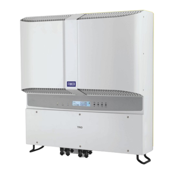
- Page 1 Product Manual PVI-10.0/12.5-TL-OUTD (10.0 to 12.5 kW)
- Page 2 Operators are required to read this manual and scrupulously follow the indications reported in it, since FIMER cannot be held responsible for damages caused to people and/or things, or the equipment, if the warranty conditions are not observed.
-
Page 3: Introduction And General Information
1 - Introduction and general information 2 - Characteristics 3 - Safety and accident prevention 4 - Lifting and transport 5 - Installation 6 - Instruments 7 - Operation 8 - Maintenance FIMER-PVI-10.0/12.5-TL-OUTD-Product manual EN-Rev D(M000023DG) EFFECTIVE 27/05/2021 © Copyright 2021 FIMER. All Rights Reserved. -
Page 4: Warranty And Supply Conditions
Not included in the supply FIMER accepts no liability for failure to comply with the instructions for correct installation and will not be held responsible for systems upstream or downstream the equipment it has supplied. -
Page 5: Table Of Contents
1- Introduction and general information Contents Introduction and general information ....................4 Warranty and Supply Conditions ......................4 Not included in the supply .......................4 Contents ..............................5 Reference number index ........................8 Graphical representation of references ....................8 Scope and target audience ........................9 Purpose and document structure ...................9 List of appendix documents ....................9 Operator and maintenance personnel skills/prerequisites .............9 Symbols ad signs ..........................10... - Page 6 1- Introduction and general information Residual risks ............................34 Table of residual risks ......................34 Lifting and transport ......................... 35 General conditions ..........................35 Transport and handling .......................35 Lifting .............................35 Unpacking and checking ......................35 List of components supplied ....................36 Weight of the groups of device .....................37 Installation ............................
- Page 7 1- Introduction and general information LED behaviour ............................69 Specifications on the operation of the LEDs.................70 LED insulation fault .......................70 Description of the menus ........................71 General information ......................71 Statistics Menu ........................73 Settings Menu ........................75 Info Menu ..........................83 AUTOTEST procedure in accordance with standard CEI 0-21 ............84 Running the tests from the display menu ................84 Maintenance ............................
-
Page 8: Reference Number Index
1- Introduction and general information Reference number index , Bracket , Input connectors (MPPT1) , Channel configuration switch , Heat sink , Input connectors (MPPT2) , Internal battery , Front cover , AC cable gland , Alarm terminal block , LED Panel , Service cable glands , Signal terminal block , Display... -
Page 9: Scope And Target Audience
1- Introduction and general information Scope and target audience Purpose and document structure This operating and maintenance manual is a useful guide that will enable you to work safely and carry out the operations necessary for keeping the equipment in good working order. If the equipment is used in a manner not specified in this manual, the protection provided by the equipment may be impaired. -
Page 10: Symbols Ad Signs
1- Introduction and general information Symbols ad signs In the manual and/or in some cases on the equipment, the danger or hazard zones are indicated with signs, labels, symbols or icons. Table: Symbols This points out that it is mandatory to consult the manual or original do- cument, which must be available for future use and must not be dama- ged in any way. -
Page 11: Field Of Use, General Conditions
1- Introduction and general information Field of use, general conditions FIMER shall not be liable for any damages whatsoever that may result from incorrect or careless operations. You may not use the equipment for a use that does not conform to that provided for in the field of use. -
Page 12: Characteristics
Characteristics General conditions A description of the equipment characteristics is provided to identify its main components and specify the technical terminology used in the ma- nual. This chapter contains information about the models, details of the equipment, characteristics and technical data, overall dimensions and equipment identification. -
Page 13: Models And Range Of Equipment
2 - Characteristics Models and range of equipment The specific models of three-phase inverters covered by this manual are divided into two groups according to their maximum output power: 10.0 kW or 12.5 kW. For inverters of equal output power the variant between the various mo- dels is the presence or lack thereof of the DC disconnect switch , or the input fuses board... -
Page 14: Identification Of The Equipment And The Manufacturer
2 - Characteristics Identification of the equipment and the manufacturer The technical data shown in this manual do not in any case replace those shown on the labels attached to the equipment. The labels attached to the equipment must NOT be removed, damaged, dirtied, hidden, etc. The approval label contains the following information: 1. - Page 15 The officially required information is located on the approval label. The identification label is an accessory label which shows the information necessary for the identification and cha- racterisation of the inverter by FIMER. N.B. The labels must NOT be hidden with objects and extraneous parts (rags, boxes, equip-...
-
Page 16: Characteristics And Technical Data
2 - Characteristics Characteristics and technical data Table: Technical Data PVI-10.0-TL-OUTD PVI-12.5-TL-OUTD Input Absolute Maximum Input Voltage (V 900 V max,abs Rated Input Voltage (V 580 V 360 V (adj. 250...500 V) Input start-up voltage (V start Input operating interval (V ...V... - Page 17 3. Limited to 10000 W for Belgium and Germany 4. Limited to 12500 W for Germany 5. Refer to the document “String inverter – Product Manual appendix” available at www.fimer.com to know the brand and the model of the quick fit connector 6.
-
Page 18: Tightening Torques
2 - Characteristics Tightening torques To maintain the IP65 protection of the system and for optimal installa- tion, the following tightening torques must be used: 5.0 Nm AC cable gland M40 (ring nut fixing) 8.0 Nm AC cable gland M40 (locknut fixing) 2.5 Nm Service cable glands M20 (ring nut fixing) -
Page 19: Bracket Dimensions
2 - Characteristics Bracket dimensions The wall mounting bracket dimensions are expressed in mm and inches 90.5 mm 3.56 in 50.0 mm 1.96 in 8.0 mm 0.31 in 25.0 mm 0.98 in 7.0 mm 0.28 in... -
Page 20: Efficiency Curves
PVI-10.0-TL-OUTD PVI-10.0-TL-OUTD - E ciency curves PVI-10.0-TL-OUTD-S PVI-10.0-TL-OUTD-FS 300 Vdc 580 Vdc 750 Vdc 100% % of Rated Output Power PVI-12.5-TL-OUTD PVI-12.5-TL-OUTD - E ciency curves PVI-12.5-TL-OUTD-S PVI-12.5-TL-OUTD-FS 360 Vdc 580 Vdc 750 Vdc 100% % of Rated Output Power... -
Page 21: Power Derating
2 - Characteristics Power derating In order to allow inverter operation in safe thermal and electrical condi- tions, the unit automatically reduces the value of the power fed into the grid. Power limiting may occur due to: • Adverse environmental conditions (thermal derating) •... -
Page 22: Power Reduction Due To The Input Voltage
Power reduction due to the input voltage The graphs show the automatic reduction of supplied power when input voltage values are too high or too low. PVI-10.0-TL-OUTD Pout Vs Vin (single input channel) PVI-10.0-TL-OUTD-S PVI-10.0-TL-OUTD-FS PVI-12.5-TL-OUTD 9000 PVI-12.5-TL-OUTD-S 8000 PVI-12.5-TL-OUTD-FS 7000 6000... -
Page 23: Characteristics Of A Photovoltaic Generator
2 - Characteristics Characteristics of a photovoltaic generator A PV generator consists of an assembly of photovoltaic panels that tran- sform solar radiation into DC electrical energy and can be made up of: Strings: X number of PV panels connected in series Array: group of X strings connected in parallel Strings and Arrays In order to considerably reduce the cost of installing a photovoltaic sy-... -
Page 24: Description Of The Equipment
2 - Characteristics Description of the equipment This equipment is an inverter that converts direct electric current from a photovoltaic generator into alternating electric current and feeds it into the national grid. Photovoltaic panels transform energy from the sun into direct current (DC) electrical energy (through a photovoltaic field, also called photovol- taic (PV) generator;... -
Page 25: Connection Of Several Inverters Together
A configuration program that can help to correctly size the photovoltaic system is available on the web site of FIMER... -
Page 26: Functionality And Components Of The Equipment
The inverter or a network of several inverters, can also be monitored remotely via an advanced communication system based on a RS-485 serial interface. The range of optional FIMER devices that can be con- nected to this communication line allow you to monitor the device locally... -
Page 27: Topographic Diagram Of The Equipment
2 - Characteristics Topographic diagram of the equipment The diagram summarises the internal structure of the inverter. The main blocks are the DC-DC input converters (called "boosters") and the output inverter. The DC-DC converter and the output inverter both work at a high switching frequency, and so are small and relatively light. Each of the input converters is dedicated to a separate array, with inde- pendent maximum power point tracking (MPPT) control. - Page 28 2 - Characteristics...
-
Page 29: Safety Devices
2 - Characteristics Safety devices Anti-Islanding In the event of a local grid outage by the electricity company, or when the equipment is switched off for maintenance operations, the inverter must be physically disconnected to ensure the protection of the people working on the grid, in accordance with the relevant national laws and regulations. -
Page 30: Safety And Accident Prevention
It is therefore necessary for the customer to appropriately inform the manufacturer about particular installation conditions. FIMER accepts no liability for failure to comply with the instructions for correct installation and cannot be held responsible for the upstream or downstream equipment. -
Page 31: Hazardous Areas And Operations
These conditions are reported on the thecnical data and on installation chapter. FIMER CANNOT be held responsible for disposal of the equipment: displays, cables, batteries, accumulators, etc., and therefore the customer must dispose of these substances, which are potentially harmful to the environment, in accordance with the regulations in force in the country of installation. -
Page 32: Thermal Hazard
Clothing and protective devices for staff FIMER has eliminated sharp edges and corners, but in some cases it is not possible to do anything, and we therefore advise wearing the clothing and personal protective devices provided by the employer. -
Page 33: Residual Risks
3 - Safety and accident prevention Residual risks Despite the warnings and safety systems, there are still some residual risks that cannot be eliminated. These risks are listed in the following table with some suggestions to prevent them. Table of residual risks RISK ANALYSIS AND DESCRIPTION SUGGESTED REMEDY Noise pollution due to installation in unsuitable environments or where... -
Page 34: Lifting And Transport
During handling, do not make any sudden or fast movements that can create dangerous swinging. Lifting FIMER usually stores and protects individual components by suitable means to make their transport and subsequent handling easier, but as a rule, it is necessary to utilize the experience of specialized staff in change of loading and unloading the components. -
Page 35: List Of Components Supplied
4 - Lifting and transport List of components supplied Supplied with the inverter are all the components required to correctly install and connect the inverter Components available for all models Bracket for wall fastening Plugs and screws for wall mounting 5 + 5 D.18 washer M40 Cable Gland... -
Page 36: Weight Of The Groups Of Device
4 - Lifting and transport Weight of the groups of device Table: Weights Weight (Kg/lb) Lifting points (no.#) INVERTER <41.0 kg / 90.4 lb... -
Page 37: Installation
Installation General conditions Equipment performance will be enhanced by proper equipment installation. Staff authorized to carry out the installation must have received suitable training on this type of equipment. Equipment operation must be carried out by staff who comply with in- structions in this manual. -
Page 38: Environmental Checks
5 - Installation Environmental checks • Consult the technical data to check the environmental parameters to be observed (degree of protection, temperature, humidity, altitude, etc.) • The installation to direct sunlight must be avoid (otherwise the warranty will be cancelled) beacuse it may cause: - phenonmena of power limitation by the inverter (with consequent reduc- tion of energy production) - premature aging of electronic/electromechanical components... -
Page 39: Installation Position
5 - Installation Installation position When choosing the place of installation, comply with the following condi- tions: • Install on a wall or strong structure suitable for bearing the weight. • Install in safe, easy to reach places. • If possible, install at eye-level so that the display and status LEDs can be seen easily. -
Page 40: Wall Mounting
5 - Installation Wall mounting During installation do not place the inverter with the front cover facing towards the ground. • Position the bracket so that it is perfectly level on the wall and use it as a boring template. •... -
Page 41: Operations Preparatory To Pv Generator Connection
Choice of differential protection downstream of the inverter All FIMER string inverters marketed in Europe are equipped with a de- vice for protection against ground faults in accordance with the safety standard set in Germany by Standard VDE V 0126-1-1:2006-02 (please refer to section 4.7 of the Standard). - Page 42 B ground fault interrupter. In accordance with article 712.413.1.1.1.2 of Section 712 of IEC Standard 64-8/7, we hereby declare that, because of their construction, FIMER inverters do not inject ground fault direct currents. The use of an AC type circuit breaker with differential thermal magnetic protection with trip- ping current of 300 mA is advisable so as to prevent false tripping, due to the normal capaci- tive leakage current of photovoltaic modules.
-
Page 43: Independent Or Parallel Input Channels Configuration
5 - Installation Independent or parallel input channels configuration All the inverter models are equipped with two input channels (thus bene- fiting from two trackers for MPPT maximum power point tracking) which work independently of one another, which can be paralleled by levera- ging a single MPPT. -
Page 44: Channel Configuration Examples
5 - Installation Channel configuration examples PV generator characteristics MPPT configu- Notes ration A NECESSARY condition so that the two The photovoltaic generator consists of strings having a different number MPPTs can be used in independent mode is for MPPT configu- of modules in series from each other. -
Page 45: Independent Channel Configuration (Default Configuration)
5 - Installation Independent channel configuration (default configuration) This configuration involves the use of the two input channels (MPPT) in independent mode. This means that the jumpers between the two channels (positive and negative) of the DC input terminal block must not be installed and the switch located on the main board must be... -
Page 46: Input Connection To Pv Generator (Dc Side)
09 10 Refer to the document “String inverter – Product Manual appendix” avai- lable at www.fimer.com to know the brand and the model of the quick fit connector. Depending on the model of the connector of the own inverter, it is necessary to use the same model and the respective counterpart (check the compliant counterpart on the website of the manufacturer or in FIMER). - Page 47 5 - Installation In the -FS version each input is supplied with protection fuses (not factory fitted) and an input polarity control. To check the polarity, connect all the strings and check that the LEDs on the fuse board are lit up; if one or more LEDs is off, the polarity of the corresponding strings is to be considered INCORRECT.
-
Page 48: String Protection Fuses (-Fs Model Only)
5 - Installation String protection fuses (-FS model only) Sizing of fuses Correctly sizing the string fuses to be used for protection against re- turn currents is very important since it can significantly reduce the risk of fire and damage to the PV generator. A “return current” can be generated in the event of a fault and relevant short-circuit at the ends of one or more PV modules of the system;... - Page 49 - Increase in Isc as a result of high temperature in the PV module - Thermal derating of the fuse - Maximum return current of the installed PV modules FIMER can supply fuse kits of different values Code Description Quantity...
-
Page 50: Installation Procedure For Quick Fit Connectors
Amphenol H4. Refer to the document “String inverter – Product Manual appendix” avai- lable at www.fimer.com to know the brand and the model of the quick fit connector. The model of connectors installed on your inverter must be matched by the same model of the respective corresponding parts to be used (che- cking the conforming corresponding part on the manufacturer’s website). - Page 51 5 - Installation 2. WEIDMÜLLER WM4 quick fit connectors Installation of Weidmüller WM4 connectors requires crimping to be carri- ed out with suitable equipment. - Strip the cable to which you want to apply the connector (after verifying that it complies with the connector limits). 4...6mm - Apply the terminal to the conductor using suitable crimping pliers.
- Page 52 5 - Installation 3. MULTICONTACT MC4 quick fit connectors Installation of Multicontact MC4 connectors requires crimping to be carri- ed out with suitable equipment. - Strip the cable to which you want to apply the connector (after verifying that it complies with the connector limits). 4...6mm - Apply the terminal to the conductor using suitable crimping pliers.
- Page 53 5 - Installation 4. AMPHENOL H4 quick fit connectors Installation of Amphenol H4 connectors requires crimping to be carried out with suitable equipment. - Strip the cable to which you want to apply the connector (after verifying that it complies with the connector limits). 4...6mm - Apply the terminal to the conductor using suitable crimping pliers.
-
Page 54: Grid Output Connection (Ac Side)
19 ÷ 28 mm The table shows the maximum length of the line conductor based on the cross-section of this conductor: Cross-section of the line conductor (mm PVI-10.0-TL-OUTD PVI-12.5-TL-OUTD 4 mm² 34 m 28 m* 6 mm² 51 m 42 m 10 mm²... -
Page 55: Load Protection Switch (Ac Disconnect Switch)
To protect the AC connection line of the inverter, we recommend install- ing a device for protection against over current and leakage with the fol- lowing characteristics: PVI-10.0-TL-OUTD PVI-12.5-TL-OUTD Type Automatic circuit breaker with differential thermal magnetic protection Voltage rating... -
Page 56: Communication And Control Board
5 - Installation Communication and control board Ref. Ref. Description inverter manual ALARM Connection to the multi-function relay WIND Connection of the Tachometer signal Connection to the remote ON/OFF RS485 Connection of the RS485 line RS485 (A) Connection of the RS485 line on RJ45 connector RS485 (B) Connection of the RS485 line on RJ45 connector 120 Ω... -
Page 57: Connections To The Communication And Control Board
5 - Installation Connections to the communication and control board Each cable which must be connected to the communication and control board must pass through one of the three service cable glands M20 , which take a cable with a diameter of 7 mm to 13 mm. Gaskets with two holes are supplied as standard to insert into the cable gland, which enables two separate cables of a maximum cross-section of 5 mm to be accommodated. -
Page 58: Serial Connection Communication (Rs485)
5 - Installation Serial Connection Communication (RS485) On the inverter there is a RS485 communication line, dedicated to con- necting the inverter to monitoring devices or to carrying out “daisy-chain” (“in-out”) connections of multiple inverters. The line may also be used to store settings with the dedicated advanced configuration software. -
Page 59: Procedure For Connection To A Monitoring System
5 - Installation Procedure for connection to a monitoring system Connect all the units of the RS485 chain in accordance with the “daisy- chain” arrangement (“in-out”) observing the correspondence between signals, and activate the termination resistance of the communication line in the last element of the chain by switching switch (to ON posi- tion). -
Page 60: Remote Control Connection
5 - Installation Remote control connection The connection and disconnection of the inverter to and from the grid can be controlled through an external control. The function must be enabled in the relevant menu. If the Remote control function is disabled, the switching on of the inverter is dictated by the presence of the normal parameters that allow the inverter to connect to the grid. -
Page 61: Instruments
We, therefore, advise that you carefully read this manual. If you are not sure about any information in this manual, please ask FIMER Service for more detailed information. Do not use the equipment if: - you do not have suitable qualifications to work on this equipment or similar products;... -
Page 62: Description Of Keyboard And Led Panel
6 - Instruments Description of keyboard and LED Panel Using the combination of keyboard keys, under the display, it is possible to set values or scroll through the data items to view them. LED indica- tors are located alongside the keyboard, indicating the operating state of the inverter. -
Page 63: Operation
Operation General conditions Before checking the operation of the equipment, it is necessary to have a thorough knowledge of the Instruments chapter 6 and the functions that have been enabled in the installation process. The equipment operates automatically without the aid of an operator; the operating state should be controlled through the equipment’s instrumen- tation. -
Page 64: Monitoring And Data Transmission
7 - Operation Monitoring and data transmission As a rule, the inverter operates automatically and does not require spe- cial checks. When there is not enough solar radiation to supply power for export to the grid (e.g. during the night), it disconnects automatically and goes into stand-by mode. -
Page 65: Commissioning
After the grid standard was set you have 24 hours to make any changes to the grid standard value; 24 hours later the “Country Select.” functionality will be blocked, and any subsequent changes can only be made using a password provided on request by FIMER. • After you have set the “Country” value, the message “Inizializing...Plea- se Wait”... - Page 66 7 - Operation • During the grid voltage check and measurement of the insulation re- sistance, the values for the grid voltage and frequency and the insula- tion resistance measured by the inverter are shown on the display. The inverter completes parallel connection with the grid SOLELY if the grid parameters meet the ranges provided for by the regulations in force and if the insulation resistance is greater than 1Mohm.
-
Page 67: Display Access And Settings
7 - Operation Display access and settings Once the inverter has been commissioned, it is possible/necessary to configure the inverter by accessing the Settings Menu directly from the display. The following are the main adjustable parameters (see the sec- tion on “Menu descriptions”) •... -
Page 68: Led Behaviour
7 - Operation LED behaviour The following table shows all the possible activation combinations of LEDs = LED On on the LED panel according to the operating status of the inverter. = LED flashing = LED Off = Any one of the conditions described above LED status Operating state... -
Page 69: Specifications On The Operation Of The Leds
7 - Operation Specifications on the operation of the LEDs In correspondence to each status of the inverter indicated by the constant or intermittent lighting of the specific LED, the display also shows a message identifying the operation which is being carried out or the defect/anomaly recorded (see specific chapter). -
Page 70: Description Of The Menus
7 - Operation Description of the menus The inverters are equipped with a Display , consisting of 2 lines of 16 characters each, which can be used to: • Display the operating state of the inverter and the statistical data •... - Page 71 Lun 22 Lug 15:55 Lun 22 Lug 15:55 DOWN DOWN Type: Outdoor inverter type (OUTD) Type OUTD P/N: FIMER product identification code P/N -3xxx- DOWN S/N: Sequential serial number S/N XXXXXX FW rel. : Firmware version installed FW rel. XXXX...
-
Page 72: Statistics Menu
7 - Operation Statistics Menu Selecting STATISTICS from the three main sub-menus gives access to: Statistics ENTER Lifetime DOWN Partial DOWN Today DOWN Last 7 days DOWN Last month DOWN Last 30 days DOWN Last 365 days DOWN User Period 1. - Page 73 7 - Operation 4. Last 7 days This section of the menu displays the statistics for the last 7 days: • E-7d: Energy produced over the last 7 days • Val. : Value of production over the last 7 days, calculated using the cur- rency and conversion coefficient set in the relevant section of the SET- TINGS menu •...
-
Page 74: Settings Menu
7 - Operation Settings Menu Selecting SETTINGS from the three main sub-menus brings up the first screen, asking for the password. The default password is "0000". This can be changed by using the display buttons, following the same procedure as always: •... - Page 75 This section of the menu is reserved for installers. A special access password is required, which may be obtained from the website https://registration.solar.fimer.com. Before connecting to the site, make sure you have all the information required to calculate your password: Inverter Model, Serial Number, week of manufacture.
- Page 76 7 - Operation The table below shows the parameters that can be changed and the range of values that may be set for each: Parameter Description Setting range Set U>> Grid over-voltage (OV) threshold (extended range) Unom … Unom x 1.3 Set U<<...
- Page 77 We advise changing the activation voltage only if really necessary and to set it to the correct value: the photovoltaic generator sizing tool available on the FIMER website will indicate whether Vstart needs changing and what value to set it at.
- Page 78 7 - Operation 10. Alarm This section of the menu allows you to set the activation status of a relay (available either as contact normally open – N.O. – or as contact normally closed – N.C.). This contact can be used, for example, to: activate a siren or a visual alarm, control the disconnect device of an external transformer, or control an external device.
- Page 79 7 - Operation • Configurable alarm with reset at the end of the alarm signalling INVERTER RUN process (display text “Alarm Conf.”) N.C. The relay is activated (state: switched) whenever an error is present Relay State: Idle N.O. (code Exxx) or a warning (code Wxxx) from those selected from the list in the dedicated submenu.
- Page 80 Under Voltage limit (set at 70% of Vstart). FIMER sets the time at 60 sec. The user can set it at any time from 1 to 3600 sec.
- Page 81 7 - Operation 14. Reactive power This section of the menu may be used to manage the supply of reactive power into the grid. There are 5 possible types of management: • No regulation: no regulation of reactive power. To enable this mode, select Enable and then OK (using the UP / DOWN arrows) •...
-
Page 82: Info Menu
7 - Operation Info Menu Selecting INFO from the three main sub-menus gives access to: Information ENTER Product ID DOWN Serial No DOWN Firmware DOWN Country Select. 1. Part No. Displays the model code. 2. Serial No. Displays the serial number and week and year of manufacture of the equipment . -
Page 83: Autotest Procedure In Accordance With Standard Cei 0-21
7 - Operation AUTOTEST procedure in accordance with standard CEI 0-21 The autotest run in accordance with grid standard CEI-021 may be initia- ted from the display menu or by using an RS485/USB converter with the dedicated interface software (Aurora Communicator). The conditions required to perform an Autotest are: •... - Page 84 7 - Operation The display shows the message “Performing Test” when the test has Test in corso started..At the end of the test, when the inverter has disconnected from the grid, the results and values of the test performed will appear on the display. You can move from one screen to another using the UP/DOWN arrow keys.
-
Page 85: Maintenance
Maintenance General conditions Routine and periodic maintenance operations must only be carried out by specialized staff with knowledge of how to perform these tasks. Maintenance operations must be performed with the apparatus disconnected from the grid (power switch open) and the photovoltaic panels obscured or isolated, unless otherwise in- dicated. -
Page 86: Routine Maintenance
PV plant. We recommend that maintenance operations be carried out by qualified personnel or by the personnel of FIMER (as set forth in a maintenance contract). The periodicity of the maintenance operations may vary in accordance with local environmen-... - Page 87 8 - Maintenance - Code on display - Error message Name of Alarm and Cause Solution - Signal • Measure the insulation resistance using a megohmmeter posi- tioned in the photovoltaic field (positive terminal short-circuited at the negative pole) compared to ground. The measurement is strongly influenced by the environmental conditions, so must be - No code Ground fault of photovoltaic generator:...
- Page 88 8 - Maintenance - Code on display - Error message Name of Alarm and Cause Solution - Signal - W010 * - Fan broken! Fan broken: • Error inside the inverter and cannot be checked externally. Yellow LED lamp. This error occurs when there is a malfunction in the fan/ - If the alarm repeats persistently, contact customer assistance.
- Page 89 8 - Maintenance - Code on display - Error message Name of Alarm and Cause Solution - Signal • Check whether the composition of the PV generator enables Input over-current (photovoltaic generator): - E001 input current which exceeds the maximum threshold allowed by The alarm occurs when the inverter's input current - Input OC the inverter and that the configuration of the inputs (independent...
- Page 90 8 - Maintenance - Code on display - Error message Name of Alarm and Cause Solution - Signal • Check that the setting of the "IN MODE" switch is specifically Incorrect configuration of inputs (set in parallel ra- set to "PAR" and that the bridges between the two input channels ther than independent): have been included.
- Page 91 8 - Maintenance - Code on display - Error message Name of Alarm and Cause Solution - Signal Failure of the test on the inverter's relay (DC-AC cir- cuit): Before connecting to the grid the inverter carries out in- • Error inside the inverter and cannot be checked externally. - E021 ternal tests.
- Page 92 8 - Maintenance - Code on display - Error message Name of Alarm and Cause Solution - Signal High leakage current (DC side): Error in the internal measurement (made when the in- - E030 verter is grid connected) of the leakage current of the •...
-
Page 93: Power Limitation Messages
8 - Maintenance - Code on display - Error message Name of Alarm and Cause Solution - Signal • Check that the inverter is not exposed to direct sunlight. Wait for Excessive temperature measured inside the inver- E056 the temperatures to which the inverter is exposed to return to the ter's wiring box: - Over Temp. - Page 94 8 - Maintenance - Message on display Name of Derating and Cause Solution - Signal Anti-islanding power limitation: The message indicates that a power limitation is active since an "islanding" condition has been recorded. - LIMxxx% CODE:03 • If the inverter remains connected to the grid and LIM xxx% = Power reduction percentage the limitation is active, contact customer assistance Display symbol b6...
-
Page 95: Registration On "Registration" Website And Calculation Of Second-Level Password (Service Menu)
“INFORMATION→Firmware”. Stage 2 - Registration on https://registration.solar.fimer.com - Go online and access https://registration.solar.fimer.com - Set the desired language and click on the specific icon to start registra- tion - Insert the personal data requested and end the registration stage - An email will be sent to the email address used with a link to complete the registration process. - Page 96 8 - Maintenance Stage 3 - Request for second level password - Go online and access https://registration.solar.fimer.com - Insert the Username (corresponding to the email used during registra- tion) and the Password obtained at the end of Stage 2 - Access the section dedicated to requesting the second-level password - Choose the inverter model from the drop-down list and insert Update Ver., Serial Number and Week of Production of the inverter which were...
- Page 97 8 - Maintenance - Click on icon to request password. Should there be an error in inputting data, the fields containing the error will be highlighted in red. If, on the other hand, the data are correct, the passwords will be shown in a new window and at the same time sent to the email address used for registration.
-
Page 98: Resetting The Time Remaining To Change The Grid Standard
2. Access the “Service” sub-menu by entering the second-level password The password to access the “Service” menu can be obtained by registering at the site https:// registration.solar.fimer.com Before accessing the site it will be necessary to locate the information utilized to compute the... -
Page 99: Replacing The Input Fuses (Version -Fs)
8 - Maintenance Replacing the input fuses (version -FS) Using fuses with inappropriate specifications may irreparably damage the unit. Any conse- quential damage to the inverter is not covered by the warranty. In case of damage of one or more input fuses, the inverter (not being able to monitor the sta- tus of fuses) will continue to export energy to the grid without signaling any alarm. - Page 100 8 - Maintenance 5. Remove the fuse holder by pressing its handle. 6. Extract the fuse to be replaced from the fuse holder by releasing the retaining clip. 7. Insert the replacement fuse into the fuse holder, checking that it is secured by the retaining clip.
-
Page 101: Replacement Of The Buffer Battery
8 - Maintenance Replacement of the buffer battery Replacement of the buffer battery may be necessary in case of: 1. Error signal on display 2. Reset of the date and time settings The battery is of the CR2032 type and is installed on the motherboard Procedure to replace the buffer battery: 1. -
Page 102: Verification Of Ground Leakage
8 - Maintenance Verification of ground leakage In the presence of anomalies or report of ground fault (where provided), there may be a ground leakage from the PV generator (DC side). To check this, measure the voltage between the positive pole and ground and between the negative pole (of the PV generator) and ground using a voltmeter whose input accepts a voltage sufficient for the dimensions of the photovoltaic generator. -
Page 103: Behaviour Of A System With Leakage
8 - Maintenance Behaviour of a system with leakage If the voltage measured between one of the two poles and ground does not tend to 0V and stabilizes on a value, there is a ground leakage from the PV generator. Example: When the measurement is made between positive pole and ground, a voltage of 200V is measured. -
Page 104: Measuring The Insulation Resistance Of Photovoltaic Generator
8 - Maintenance Measuring the insulation resistance of photovoltaic generator To measure the insulation resistance of the PV generator compared to ground , the two poles of the PV generator must be short-circuited (using a suitably sized switch). Once the short-circuit has been made, measure the insulation resistance (Riso) using a megohmmeter positioned between the two shorted poles and ground (of the inverter). -
Page 105: Storage And Dismantling
Storage of the equipment or long period of non-use If the equipment is not being currently used or is to be stored for a long period of time, check that it is correctly packed and contact FIMER for storage instructions. -
Page 106: Contact Us
With regard to purchase orders, the agreed Any reproduction, disclosure to third parties or representative or visit: particulars shall prevail. FIMER does not accept utilization of its contents – in whole or in parts – is any responsibility whatsoever for potential errors or forbidden without prior written consent of FIMER.
Need help?
Do you have a question about the PVI-12.5-TL-OUTD and is the answer not in the manual?
Questions and answers