Avigilon H4A-THC-BO Installation Manual
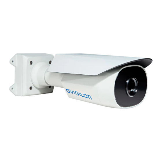
H4 series thermal camera
Hide thumbs
Also See for H4A-THC-BO:
- User manual (43 pages) ,
- Installation manual (27 pages) ,
- User manual (56 pages)
Table of Contents
Advertisement
Advertisement
Table of Contents

Subscribe to Our Youtube Channel
Related Manuals for Avigilon H4A-THC-BO


Summary of Contents for Avigilon H4A-THC-BO
-
Page 1: Installation Guide
Installation Guide Avigilon H4 Thermal Camera Models: H4A-THC-BO... - Page 2 Power Source” with output rated 12 VDC or 24 VAC, 8 W min. or Power over Ethernet (PoE), rated 48 VDC, 8 W min. Any external power supply connected to this product may only be connected to another Avigilon product of the same model series. External power connections must be properly insulated. ...
- Page 3 Consult the dealer or an experienced radio/TV technician for help. Changes or modifications made to this equipment not expressly approved by Avigilon Corporation or parties authorized by Avigilon Corporation could void the user’s authority to operate this equipment. Disposal and Recycling Information When this product has reached the end of its useful life, please dispose of it according to your local environmental laws and guidelines.
-
Page 4: Legal Notices
The contents of this document and the specifications of the products discussed herein are subject to change without notice. Avigilon Corporation reserves the right to make any such changes without notice. Neither Avigilon Corporation nor any of its affiliated companies: (1) guarantees the completeness or accuracy of the information contained in this document;... -
Page 5: Table Of Contents
Table of Contents Overview Mounting Bracket View Rear View Front View Configuration Panel View Side View Installation Camera Package Contents Installation Steps Mounting and Aiming Video Analytics Cameras Installing the Mounting Bracket (Optional) Removing the Sun Shroud Reinstalling the Sun Shroud Connecting Cables Mounting the Camera Removing the Configuration Panel Cover... -
Page 6: Overview
Overview Mounting Bracket View 1. Camera mounts Points for installing the camera to the mounting bracket. 2. Mounting hook slots Points to hold the camera to the mounting bracket while connecting the required cables. 3. Mounting holes Holes for securing the mounting bracket to the mounting surface. Overview... -
Page 7: Rear View
Rear View 1. Ethernet port Accepts an Ethernet connection to a network. Server communication and image data transmission occurs over this connection. Also receives power when it is connected to a network that provides Power over Ethernet. 2. Camera mounting screws Screws for mounting the camera to the mounting bracket. -
Page 8: Front View
Front View 1. Configuration panel cover Covers the configuration panel. For more information on the configuration panel, see the Configuration Panel View on the next page. Front View... -
Page 9: Configuration Panel View
3. Connection status LED indicator Provides information about device operation. For more information, see Connection Status LED Indicator on page 15. 4. Micro USB port Accepts a micro USB to USB adapter. Only required when using the Avigilon USB Wi-Fi Adapter. Configuration Panel View... -
Page 10: Side View
Side View 1. Sun shroud An adjustable cover to help protect the lens against glare from the sun. 2. Mount arm Adjustable mount arm for positioning the camera. 3. Adjustment screws Provides a locking mechanism for the mount arm. Side View... -
Page 11: Installation
The camera should be mounted to a stable surface to minimize the physical movement of the camera after installation. For more details, see Designing a Site for Video Analytics. This document is available in the Avigilon eDocs app and on the Avigilon website. -
Page 12: (Optional) Removing The Sun Shroud
1. Use the mounting template to drill four mounting holes into the mounting surface. 2. Drill the cable entry hole into the mounting surface then pull the required cables through the cable entry hole. 3. Fasten the mounting bracket to the mounting surface or junction box. NOTE: It is recommended that silicone sealant be applied around the edge of the mounting bracket to prevent moisture from entering the mounting surface. -
Page 13: Connecting Cables
Connecting Cables Before connecting any cables, ensure that the cable connections are properly protected from moisture and corrosion. The optional junction box (H4-BO-JBOX) provides a watertight seal that helps prevent moisture from corroding the cable connections. If you are not using the optional junction box, make sure the protective cable boot is installed over the Ethernet port to protect the connection from dust and moisture. -
Page 14: Mounting The Camera
Power over Ethernet (PoE) Class 3 — If PoE is available, the camera LEDs will turn on. External Power — Connect an external 12 V DC or 24 V AC power source through the brown and blue auxiliary power cables. Important: Be careful not to connect power to the audio input cable, doing so will permanently damage the camera. -
Page 15: Removing The Configuration Panel Cover
For more information about configuring the camera from the mobile web interface see Avigilon USB Wi-Fi Adapter System User Guide. NOTE: The camera will reserve the 10.11.22.32/28 subnet for internal use while the USB Wi-Fi Adapter is plugged in. -
Page 16: Accessing The Live Video Stream
4. Tighten the adjustment screws on the mount arm to secure the camera’s position. 5. In the camera web browser interface or the Avigilon Control Center software adjust the camera’s Image and Display settings. You can change the image rotation. -
Page 17: Configuring The Camera
For more information, see the Avigilon Camera Configuration Tool User Guide. If the camera is connected to the Avigilon Control Center system, you can use the client software to configure the camera. For more information, see the Avigilon Control Center Client User Guide. -
Page 18: Connecting To Power And External Devices
Connecting to Power and External Devices Important: Be careful not to connect auxiliary power to the audio input wire or the camera will be damaged. Although both the audio input wire and auxiliary power wire are brown, the auxiliary power wire is distinguished by its thicker wire gauge and AUX PWR label. - Page 19 5. Red — Digital Input 6. Pink — Digital Output 7. Purple — Reserved Wire, do not connect. 8. White — Reserved Wire, do not connect. * — Relay ** — Switch M — Microphone S — Speaker ...
-
Page 20: Connection Status Led Indicator
Connection Status LED Indicator Once connected to the network, the Connection Status LED indicator will display the progress in connecting to the Network Video Management software. The following table describes what the LED indicator shows: Connection Status Connection State Description LED Indicator One short flash every Obtaining IP Address... -
Page 21: Resetting To Factory Default Settings
Resetting to Factory Default Settings If the device no longer functions as expected, you can choose to reset the device to its factory default settings. Use the firmware revert button to reset the device. The firmware revert button is shown in the following diagram: For models that feature an SD card slot, resetting the camera will not affect video that has been recorded to the SD card. -
Page 22: Setting The Ip Address Using The Arp/Ping Method
For more information, see the Web User Interface Guide - Avigilon High Definition H.264 IP Camera Models. 1. Locate and copy down the MAC Address (MAC) listed on the Serial Number Tag for reference. -
Page 23: Specifications
Specifications Camera Audio Input/Output Line level input and output 320S-H4A-THC: (BO50 model) 4.3mm, F1.0, Athermalized Lens (BO24 model) 9.1mm, F1.0, Athermalized (BO12 model) 18.0mm, F1.0, Athermalized SD Storage (Models with SD card SD/SDHC/SDXC slot – minimum class 4; class 6 or better recommended slots only) Network Network... - Page 24 VAC: 24 V +/- 10%, 15 VA min PoE: IEEE802.3af Class 3 RTC Backup Battery 3V manganese lithium Environmental Operating -40 °C to +65 °C (-40 °F to 149 °F) Temperature Storage -10 °C to +70 °C (14 °F to 158 °F) Temperature Humidity 0-93% non-condensing...
-
Page 25: Limited Warranty And Technical Support
Limited Warranty and Technical Support Avigilon warranty terms for this product are provided at avigilon.com/warranty. Warranty service and technical support can be obtained by contacting Avigilon Technical Support: avigilon.com/contact-us/. Limited Warranty and Technical Support...
Need help?
Do you have a question about the H4A-THC-BO and is the answer not in the manual?
Questions and answers