Advertisement
Quick Links
EN
EN
INSTALLATION AND SERVICING INSTRUCTIONS
INSTALLATION AND SERVICING INSTRUCTIONS
USER, INSTALLATION AND SERVICING INSTRUCTIONS
To consult the documentation,
visit our website www.sime.it
BRAVA DGT HE
BRAVA DGT HE
Aluminium condensation boilers
ALU PLUS HE
25 - 30 - 35
25 - 30 - 35
TRANSLATION OF THE ORIGINAL INSTRUCTIONS
Cod. 6316191 - 08/2013
6330935A - 04/2023 - R3
Cod. 6316191 - 08/2013
ENSURE THAT THESE
ENSURE THAT THESE
INSTRUCTIONS ARE LEFT
INSTRUCTIONS ARE LEFT
FOR THE USER AFTER
FOR THE USER AFTER
COMPLETION OF THE
COMPLETION OF THE
BENCHMARK SECTION
BENCHMARK SECTION
PLEASE READ THE
PLEASE READ THE
IMPORTANT NOTICE
IMPORTANT NOTICE
WITHIN THIS GUIDE
WITHIN THIS GUIDE
REGARDING YOUR BOILER
REGARDING YOUR BOILER
WARRANTY
WARRANTY
199838
199838
199839
BOILER DETAILS
please position here a sticker
from installation pack
Advertisement

Related Manuals for Sime ALU PLUS HE


Summary of Contents for Sime ALU PLUS HE
- Page 1 6330935A - 04/2023 - R3 Cod. 6316191 - 08/2013 BRAVA DGT HE BRAVA DGT HE Aluminium condensation boilers ALU PLUS HE 25 - 30 - 35 25 - 30 - 35 INSTALLATION AND SERVICING INSTRUCTIONS INSTALLATION AND SERVICING INSTRUCTIONS USER, INSTALLATION AND SERVICING INSTRUCTIONS...
- Page 2 For the first year all of our appliances are protected by our manufacturer’s guarantee which covers both parts and labour. As you would expect from Sime Ltd, it is our aim to provide our valued customers with the best in after sales and service.
- Page 4 The Benchmark Scheme Sime is a licensed member of the Benchmark Scheme which aims to improve the standards of installation and com- missioning of domestic heating and hot water systems in the UK and to encourage regular servicing to optimise safety, efficiency and performance.
- Page 5 Sime recommends that warranty with immediate effect. maintenance and checks are carried – Fonderie SIME S.p.A. reserves the right out at least ONCE A YEAR or according to make improvements to its prod- to the specific legal provisions .
- Page 6 RESTRICTIONS DO NOT DO NOT – To allow children under the age of 8 to – To block the condensate drain. use the appliance. The appliance can – To pull, detach or twist the electrical be used by children no younger than cables coming out of the appliance 8 years old, by people with physical or even if the appliance is disconnected...
- Page 7 USER INSTRUCTIONS ALU PLUS HE 1100 8115781 TABLE OF CONTENTS COMPLIANCE Our company declares that ALU PLUS HE boilers comply with the following directives: DESCRIPTION OF THE APPLIANCE – Gas Appliances EU Regulation 2016/426 – Low Voltage Directive 2014/35/UUE TABLE OF CONTENTS –...
- Page 9 2012/19/EU) ........13 Fault / malfunction codes ......12 SIME remote control connection (optional accessory) . 12 VERY IMPORTANT! PLEASE MAKE SURE YOUR COMMISSIONING CHECKLIST AND THE SERVICE INTERVAL RECORDS ENCLOSED ARE FILLED IN CORRECTLY.
- Page 10 Control panel ON/OFF BUTTON The control panel allows all operators to make all adjustments necessary to manage Sime ALU PLUS HE boilers and connected ON = Boiler has electric power. systems. OFF = Boiler has electric power but is not available for operation.
- Page 11 Start-up Adjusting the delivery temperature The control panel on ALU PLUS HE boilers lets you manually 1.2.1 Preliminary checks adjust the delivery temperature on two temperature levels by choosing the best ones for the systems managed (e.g. 80°C and 50°C).
- Page 12 SIME remote control connection (optional then released. The boiler starts up again normally. accessory) The boiler is ready for connection to a SIME remote control. When the remote control is connected or, alternatively, when a remote supervision device is connected, the boiler display...
- Page 13 MAINTENANCE DISPOSAL Servicing Disposal of the equipment (European Directive 2012/19/EU) For the appliance to operate correctly and efficiently it is rec- ommended that the system manager calls upon the services At the end of their life span, the appliance and of a Professionally Qualified Technician to carry out ANNUAL electrical and electronic devices coming from maintenance.
- Page 15 DESCRIPTION OF THE APPLIANCE TABLE OF CONTENTS Technical features ......20 DESCRIPTION OF THE APPLIANCE Main water circuit .
- Page 16 The system should include an INAIL safety device 8101596 (for 360 ALU PLUS HE ) or 8101597 (for 720 - 1100 ALU ), which are mandatory for ITALY ONLY, and a plate heat...
- Page 17 Identification Domestic hot water can be produced if the system has a dhw The ALU PLUS HE boilers can be identified by means of: circuit with a storage tank. The dhw system can be created ei- this is located on the outside of the pack- Packaging label: ther upstream or downstream of the water shut-off valve.
- Page 18 CONDENSATION CONDENSATIEKETEL CODE GASBRENNWERTKESSEL - - KONDENZACIJSKI KOTEL - PLYNOVÝ KONDENZA I KOTEL - CONDENSARE CAZAN - KOCIOL KONDENSACYJNY - KONDENZÁCIÓS YEAR OF MANUFACTURE ALU PLUS HE 1100 8115781 N° PIN 2018 9999999999 PIN n. 1312CS6203 1312 WATER CONTENT IN BOILER...
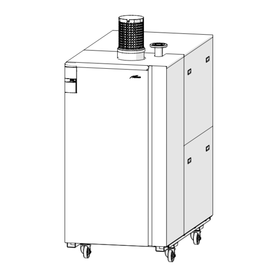
- Page 19 Structure Combustion air inlet (optional accessory) Front panel Ignition transformer Gas valve Structure Wheel Water pressure sensor Inspection and cleaning door Return manifold Return sensor (SR) Condensate collection tank Condensate siphon outlet Condensate outlet fitting Smoke outlet fitting Boiler drain valve Boiler return Inspection and cleaning doors Boiler delivery...
- Page 20 Technical features ALU PLUS HE DESCRIPTION 1100 CERTIFICATIONS AT - BE - CH - CY - CZ - DK - EE - ES - FI - FR - GB - GR - HU Country of intended installation IE - IT - LT - LV - NL - NO - PT - RO - SE - SI - SK - UA...
- Page 21 Main water circuit Fig. 7 KEY: Automatic bleed M Boiler delivery Delivery sensor R Boiler return Safety thermostat G Gas supply Min. gas pressure switch Sc Condensate outlet Mixer and air conveyor Gas valve Water pressure transducer Return sensor (SR) Condensate siphon outlet Boiler drain valve...
- Page 22 ΔT of 25°C at maximum heat input. able for the fuse installed on the electrical panel (4AT). The table below shows the minimum water flow rate required for each boiler. ALU PLUS HE DESCRIPTION 1100 Minimum water flow rate 5,00 (at Qmin ΔT 35°C)
- Page 23 4.10 Control panel The control panel allows all operators to make all adjustments DESCRIPTION OF COMMANDS necessary to manage Sime ALU PLUS HE boilers and connected ON/OFF BUTTON systems. ON = Boiler has electric power. OFF = Boiler has electric power but is not available for operation.
- Page 24 4.11 Wiring diagram ALU PLUS HE 360 GREEN TPAC BLUE GREEN BLACK BLACK GREEN BLACK BLUE BLUE GREEN BLUE 49 50 BROWN BLUE CN12 SBL/SA BROWN CN13 CN14 CN11 CN10 CN18 BLUE 0...10VDC BLUE BROWN KAPI BROWN BLUE BLUE BROWN...
- Page 25 - ALU PLUS HE 1100 ALU PLUS HE 720 GREEN TPAC BLUE GREEN BLACK BLACK WHITE BLACK BLUE VE1 VE2 VE3 PE BLUE GREEN BLUE 49 50 BROWN BLUE CN12 SBL/SA BROWN CN13 CN14 CN11 CN10 CN18 BLUE 0...10VDC BROWN...
- Page 26 – Connect the earth wire to an effective earthing sys- power supply through a fused mains switch, with tem. Sime declines all responsible for any injury or at least 3mm spacing between contacts, fused at damage to persons, animals,or property as a result of...
- Page 28 The Benchmark Scheme Benchmark places responsibilities on both manufacturers and installers. The purpose is to ensure that customers are provided with the correct equipment for their needs, that it is installed, commis- sioned and serviced in accordance with the manufacturer’s instructions by competent persons and that it meets the require- ments of the appropriate Building Regulations.
- Page 29 INSTALLATION AND SERVICING INSTRUCTIONS Installer Checklist Please remember to carry out the following checks after installation. This will achieve complete customer satisfaction, and avoid unnecessary service calls. A charge will be made for a service visit where the fault is not due to a manufacturing defect.
- Page 30 Technical Service or by qualified professionals who suitable protective safety equipment. MUST wear Receiving the product Appliances Sime ALU PLUS HE are supplied in a single package, protected by a nylon cover, placed on wooden pallets. Fig. 14 ALU PLUS HE...
- Page 31 Adding Fernox F1 or Mb-1 will suitably protected from the weather. guard against corrosion. – Sime promote the fitting of TF1 System filter with any new boiler installation. New installation or installation of a re- – It is important to check the inhibitor concentration after in-...
- Page 32 CAUTION Plumbing connections – The condensate outlet duct must be airtight, suita- The dimensions of the water fittings of Sime ALU PLUS HE boil- bly sized to that of the siphon and must not be re- ers are given below.
- Page 33 WARNINGS 5.11 Smoke outlet and combustion air inlet – When the Sime ALU PLUS HE boiler takes in combus- boilers are "Type B" (B23 - B23P). Sime ALU PLUS HE tion air from the place of installation it MUST BE...
- Page 34 SF-SF1 Flue gas damper consent (Max 4A - 230V) PC-PC1 Connections for pump operating signal Flue gas damper - ALU PLUS HE 1100 ALU PLUS HE 720 9 10 11 12 13 14 15 16 17 18 19 20 400V-3N 50 Hz Fig.
- Page 35 – to use cables with a cross-section of less than 1 – to use the water pipes to earth the appliance. declines all responsible for any injury or damage to (*) Sime persons, animals,or property as a result of failure to pro- vide adequate earthing of the appliance.
- Page 36 Cascade output = Boiler output x no. of boilers installed CAUTION – When systems using ALU PLUS HE single or cascade boilers are managed by MODBUS systems, Sime kits CANNOT be used to manage mixed circuits or the solar circuit.
- Page 37 5.13.1 Main hydraulic diagrams Full hydraulic diagram KEY: External sensor Room thermostat for boiler activa- tion Boiler delivery Boiler return INAIL safety unit (Italy only) Vsic Relief valve Hydraulic separator Primary circuit pump Condensate neutraliser Zone ambient thermostat Zone relays Direct zone pump Mix 1 Zone pump (only for installations with a SINGLE boiler)
- Page 38 MIX 1 ZONE KIT (code 8092275) and MIX 2 ZONE KIT (code 8092276). When systems using ALU PLUS HE single or cascade boilers are managed by MODBUS systems, Sime kits CANNOT be used to manage mixed circuits or the solar circuit. You MUST use external devices.
- Page 39 Hydraulic diagram with tank after hydraulic separator Italy only Mix 1 Zone kit code 8092275 Vsic VMIX 1 P MIX 1 Smz1 Hydraulic diagram with tank before hydraulic separator Italy only Mix 1 Zone kit code 8092275 Vsic VMIX 1 PMIX 1 Smz1 KEY:...
- Page 40 Underfloor heating hydraulic diagram Italy only Solar kit code 8092275 Vsic VMX1 PMIX 1 Smz1 VZ 1 VZ 2 KEY: External sensor Primary circuit pump Mix 1 Zone pump Room thermostat for boiler ac- Condensate neutraliser (only for installations with a SINGLE boiler) tivation Auxiliary sensor (system de- VMIX 1...
- Page 41 Fig. 28 5.14.2 SYSTEM Filling boilers DO NOT have a device to fill the boil- Sime ALU PLUS HE er/system and an emptying tap. Therefore these must be pro- vided, during installation, assembled in the most convenient places for the installer.
- Page 42 COMMISSIONING When heat is requested from the systems the boiler or the cas- Preliminary operations cade automatically carries out: – the operational checks WARNING – ignition and starts automatic operation. Should it be necessary to access the areas in the bot- tom part of the appliance, make sure that the system CAUTION components and pipes are not hot (risk of burning).
- Page 43 List of parameters Parameters PAR 01 and PAR 02 are factory-set according to TABLE “B” (possible values of PAR 02 depending on the hy- Table “A” and automatically generate the setting of parameters draulic and system configurations) PAR 04 - PAR 08 - PAR 18 and PAR 31 according to the values Description indicated in Table “A”.
- Page 44 Type Description Range Step Default 1 = QAA73 2 = QAA53 Opentherm device 3 = RVS43.143 4 = RVS46.530 5 = RVS61.843 External Sensor Value Correction -5...+5 °C - - = always seconds Duration of Backlighting 0 = never x 10 1…199 - - = no modul.
- Page 45 Resolve the problem and start-up the boiler again. Configuring the auxiliary sensor Below is the procedure for configuring the storage tank sensor NOTE: When, in addition to the message "ALL ..." the symbol (SBL) or the auxiliary sensor (e.g. system delivery sensor, SMi). also appears on the display, after having repaired the –...
- Page 46 – with the boiler inactive, loosen the screw on the mains tap- ping point (1) on the gas valve and connect a pressure gauge - 720 - 1100 ALU PLUS HE 360 GAS VALVE ALU PLUS HE 360 - 720 - 1100 Fig.
- Page 47 Operating data display Once the boiler is operating, a qualified technician can view the operating data. To access the information, press the button. The first piece of information is shown on the display. Each time this button is pressed, the next piece of information is shown. If the button is not pressed, the system exits the function automatically.
- Page 48 18. Heating return sensor value (SR) 29. Valve close command with MIX 2 ZONE board, respectively ON and OFF 30. Solar sensor temperature with solar board 19. Cascade manifold sensor value 31. Solar sensor temperature with solar board 20. Mixed system delivery probe value with MIX 1 ZONE board 32.
- Page 49 MAINTENANCE Servicing Burner Inspection For the appliance to operate safely, correctly and efficiently, 7.3.1 Cleaning the burner current legislation requires that the system manager call upon the services of a professionally qualified technician to carry out To clean the burner: regular maintenance, at least annually or according to the spe- –...
- Page 50 – Use a rod suitable for mechanically cleaning the boiler body the flame detection sensor (18). ducts (e.g. Sime accessory (9) code 6077930). A chemical If necessary replace them, taking care that gaskets (15) and product can be used provided it is suitable for aluminium (16) are not damaged during their extraction.
- Page 51 7.3.5 Connecting the air pressure switch and siphon 7.3.6 Diagram for the connection of the gas valve to the air conveyor The Teflon and silicone tubes of the air pressure switches (1) The Teflon tube of the gas valve (1) and of the air conveyor (2) and siphon (2) MUST be reconnected, where it was necessary MUST be reconnected, where it was necessary to disconnect it, to disconnect them, as shown in the picture:...
- Page 52 Type of malfunction or Shown on display Cause Solution fault - Check whether there is little water in the system - Check the primary circulation pump The boiler stops due to activation of Safety thermostat or - Check for possible obstruction of condensate drain the safety thermostat or the siphon siphon pressure switch - Check the electrical wiring and connections of the...
- Page 53 Type of malfunction or Shown on display Cause Solution fault S2 solar exchanger probe The probe on the solar exchanger is - Check the sensor and its board connections fault (tank) open or has short-circuited - Check operation of the board The delivery probe on the 2nd S3 2nd solar system deliv- - Check the sensor and its board connections...
- Page 55 CASCADING SYSTEMS TABLE OF CONTENTS CASCADING SYSTEMS EXPLODED VIEWS Cascade characteristics ......56 10 APPENDIX 1 (GUIDANCE HHIC) Characteristics of cascading boilers .
- Page 56 CASCADING SYSTEMS Cascade characteristics Approximate clearance measurements Each boiler connected in a cascade must be identified with a specific address than can be set under the relevant parameter (PAR 15), which determines how it behaves. WARNINGS For the cascade to function correctly, the external temperature sensor (SE) must be installed.
- Page 57 The cascade CANNOT be composed of different boiler cific cascade board as standard. The cascade can be made up models (e.g. two ALU PLUS HE 360 and one ALU PLUS of between two and eight boilers of the same model (e.g. three...
- Page 58 Technical features ALU PLUS HE DESCRIPTION 1100 CERTIFICATIONS AT - BE - CH - CY - CZ - DK - EE - ES - FI - FR - GB - GR - HU Country of intended installation IE - IT - LT - LV - NL - NO - PT - RO - SE - SI - SK...
- Page 59 Fig. 44 separately on request. Smoke outlet connections ALU PLUS HE D E S C R I P - TION 1100 Øi (internal...
- Page 60 Electrical connections for the cascade The electrical connections between the Sime ALU PLUS HE boil- WARNINGS ers which make up the cascade are shown in the following dia- – The external temperature sensor “SE” is OBLIGATORY gram, and the wiring diagrams for the individual appliances are and MUST be connected to the master boiler shown on the next few pages.
- Page 61 8.10 Master boiler wiring diagram ALU PLUS HE 360 GREEN TPAC BLUE GREEN BLACK BLACK GREEN BLACK BLUE BLUE GREEN BLUE 49 50 BROWN BLUE CN12 SBL/SA BROWN CN13 CN14 CN11 CN10 CN18 BLUE 0...10VDC BLUE BROWN KAPI BROWN BLUE...
- Page 62 - ALU PLUS HE 1100 ALU PLUS HE 720 GREEN TPAC BLUE GREEN BLACK BLACK WHITE BLACK BLUE VE1 VE2 VE3 PE BLUE GREEN BLUE 49 50 BROWN BLUE CN12 SBL/SA BROWN CN13 CN14 CN11 CN10 CN18 BLUE 0...10VDC BROWN...
- Page 63 8.11 Wiring diagram for slave 1 boiler ALU PLUS HE 360 GREEN TPAC BLUE GREEN BLACK BLACK GREEN BLACK BLUE BLUE GREEN BLUE 49 50 BROWN BLUE CN12 SBL/SA BROWN CN13 CN14 CN11 CN10 CN18 BLUE BLUE BROWN KAPI BROWN...
- Page 64 - ALU PLUS HE 1100 ALU PLUS HE 720 GREEN TPAC BLUE GREEN BLACK BLACK WHITE BLACK BLUE VE1 VE2 VE3 PE BLUE GREEN BLUE 49 50 BROWN BLUE CN12 SBL/SA BROWN CN13 CN14 CN11 CN10 CN18 BLUE BROWN BLUE...
- Page 65 8.12 Wiring diagram for slave 2-7 boilers ALU PLUS HE 360 GREEN TPAC BLUE GREEN BLACK BLACK GREEN BLACK BLUE BLUE GREEN BLUE 49 50 BROWN BLUE CN12 SBL/SA BROWN CN13 CN14 CN11 CN10 CN18 BLUE BLUE BROWN KAPI BROWN...
- Page 66 - ALU PLUS HE 1100 ALU PLUS HE 720 GREEN TPAC BLUE GREEN BLACK BLACK WHITE BLACK BLUE VE1 VE2 VE3 PE BLUE GREEN BLUE 49 50 BROWN BLUE CN12 SBL/SA BROWN CN13 CN14 CN11 CN10 CN18 BLUE BROWN BLUE...
- Page 67 Default tion ters Choosing 0 = fixed set The parameters for Sime ALU PLUS HE boilers in a cascade can the cascade 1 = dynamic be displayed and set in the same way as with single boilers (see strategy Number “Parameter setting and display”...
- Page 68 Benchmark Commissioning & Warranty Validation Service Record It is a requirement that the boiler is installed and commissioned to the manufacturers’ To instigate the boiler warranty the boiler needs to be registered with the manufacturer within one month of the installation. The warranty rests with the end-user (consumer), and they should be made aware it is ultimately their responsibility to register with the manufacturer, within the allotted time period.
- Page 69 GAS BOILER SYSTEM COMMISSIONING CHECKLIST & WARRANTY VALIDATION RECORD Address: Boiler make and model: Boiler serial number: Commissioned by (PRINT NAME): Gas Safe registration number: Company name: Telephone number: Company email: Company address: Commissioning date: Heating and hot water system complies with the appropriate Building Regulations? Time, temperature control and boiler interlock provided for central heating and hot water Boiler Plus requirements (tick the appropriate box(s)) Weather compensation...
- Page 70 SERVICE & INTERIM BOILER WORK RECORD It is recommended that your boiler and heating system are regularly serviced and maintained, in line with manufacturers’ instructions, and that the appropriate service / interim work record is completed. Service provider When completing a service record (as below), please ensure you have carried out the service as described in the manufacturers’ instructions. Always use the SERVICE/INTERIM WORK ON BOILER SERVICE/INTERIM WORK ON BOILER Date:...
- Page 71 SERVICE & INTERIM BOILER WORK RECORD It is recommended that your boiler and heating system are regularly serviced and maintained, in line with manufacturers’ instructions, and that the appropriate service / interim work record is completed. Service provider When completing a service record (as below), please ensure you have carried out the service as described in the manufacturers’ instructions. Always use the SERVICE/INTERIM WORK ON BOILER SERVICE/INTERIM WORK ON BOILER Date:...
- Page 72 EXPLODED VIEWS ALU PLUS HE 360 - 720 - 1100...
- Page 73 ALU PLUS HE 360 - 720...
- Page 74 ALU PLUS HE 1100...
- Page 75 ALU PLUS HE 360...
- Page 76 ALU PLUS HE 720...
- Page 77 ALU PLUS HE 1100...
- Page 78 ALU PLUS HE 360 - 720 - 1100...
- Page 79 ALU PLUS HE ALU PLUS HE Pos. Code Description Pos. Code Description 1100 1100 5204260 Complete boiler block 1010152 Pipe Ø 203 flexible 5204270 Complete boiler block 6225750 Air pressure switch 5204280 Complete boiler block 6225753 Air pressure switch 6278346 Burner...
- Page 80 ALU PLUS HE ALU PLUS HE Pos. Code Description Pos. Code Description 1100 1100 6305000 Cover 108 6301467 Main P.C.B. converter 6305010 connection cover 109 6190407 Contactor 6305020 Time programmer cover 700 5200950 Complete control panel Rotation control panel 700 5200960 Complete control panel...
- Page 81 10 APPENDIX 1 (GUIDANCE HHIC) Manufacturers Instructions Manufacturer’s instructions must be followed for the correct connection of the condensate discharge pipe from the boiler as this may vary due to the design of the boiler. For example a visible air break and trap is not required if there is a trap with a minimum condensate seal of 75 mm incorporated into the boiler.
- Page 82 Figure 1 – Connection of condensate discharge pipe to internal soil and vent stack. Note – Check manufacturer’s instructions to see if an air break is required. Boiler Visible air break 75 mm trap Visible air break and trap not required if there is a trap with a minimum condensate seal of 75 mm incorporated into the boiler Soil and vent stack Invert...
- Page 83 Internal Condensate Pipe Discharge Termination Figure 2(a) – Connection of a condensate discharge pipe downstream of a sink, basin, bath or shower waste trap. Note – Check manufacturer’s instructions to see if an air break is required. Boiler Visible air break 75 mm trap Visible air break and trap not required if there is a trap with a minimum condensate seal of 75 mm incorporated into the boiler.
- Page 84 Internal Condensate Pipe Discharge Termination Figure 2(b) – Connection of a condensate discharge pipe upstream of a sink, basin, bath or shower waste trap Boiler Visible air break at plug hole – alternative connection can be below sink trap 75 mm sink, basin, bath or shower waste trap Open end of condensate discharge pipe direct into gully 25 mm min below grating but above water level;...
- Page 85 Internal Condensate Pipe Discharge Termination The possibility of waste pipes freezing downstream of the connection point should be considered when determining a suitable connection point - e.g. a slightly longer pipe run to an internal soil stack may be preferable to a shorter run connecting into a kitchen waste pipe discharging directly through the wall to an external drain.
- Page 86 Internal Condensate Pipe Discharge Termination Figure 3 – Connection of a condensate pump - typical method (NB manufacturer’s detailed instructions should be followed). Note – Any external pipe work should be insulated, pipe cut at 45 degrees and a drain/ leaf Condensate discharge from boiler Condensate pump Visible air break at plug hole...
- Page 87 External Connections External Connections pumped connection is impractical to install. The pipe work from the boiler should be of a minimum 19mm ID or as per manufacturer’s instructions and the condensate discharge pipe shall be run in a standard drainpipe material, e.g. poly (vinyl chloride) (PVC), un-plasticized poly (vinyl chloride) (PVC-U), acrylonitrile butadiene-styrene (ABS), polypropylene (PP) or chlorinated poly (vinyl chloride) (PVC-C).
- Page 88 External Connections Figure 4 – Connection of condensate discharge pipe to external soil and vent stack Boiler Visible air break 75 mm trap Visible air break and trap not required if there is a trap with a minimum condensate seal of 75mm incorporated into the boiler.
- Page 89 External Connections Alternative Solutions Cold weather protection methods approved or endorsed by boiler manufacturers and/or service organisations may be adopted if these are considered suitable by the parties involved. It is the responsibility of the manufacturer of these products to ensure they have completed the necessary testing or calculations to ensure the product offers suitable protection to prevent the condensate pipe from freezing.
- Page 90 External Connections Electric Trace Heating condensate pipe to raise the temperature of the condensate pipe in freezing conditions. Trace heating takes the form of an electrical heating element run in physical contact along the length of the condensate pipe. The pipe is usually covered with thermal insulation to retain heat losses from the pipe.
- Page 91 External Connections Figure 5 – External termination to rainwater downpipe (NB only combined foul/rainwater drain) Condensate discharge pipe from boiler Pipe size transition point Water/weather proof insulation 43mm 90° male/female bend External rain water pipe into foul water External air break Air gap Minimum internal diameter 19mm Minimum internal diameter 30mm...
- Page 92 External Connections External Termination of the Condensate Pipe Where the condensate discharge pipe is terminated over an open foul drain or gully, the pipe should terminate below the grating level, but above water level, in order to minimise “wind chill” at the open end. Pipe drainage and resistance to freezing will be improved if the termination end of the condensate pipe is cut at 45 degrees as opposed to a straight cut.
- Page 93 External Connections Figure 6 – External drain, gully or rainwater hopper Boiler Visible air break 38mm minimum trap Visible air break and trap not required if there is a trap with a minimum condensate seal of 38 mm incorporated into the boiler – refer to manufacturers instructions External length of pipe 3 m maximum Open end of condensate discharge pipe direct into gully 25 mm min below grating but above water level;...
- Page 94 External Connections Figure 7 – Example of a purpose made soakaway Condensate discharge pipe from boiler Ground (this section of the condensate discharge pipe may be run either above or below round level); End cut at 45° Diameter 100 mm minimum plastic tube Bottom of tube sealed Limestone chippings Two rows of three 12 mm holes at 25 mm centres, 50 mm from bottom of tube and facing...
- Page 95 Turn off appliance and call SIME LTD Technical HelplIne for advice. NOTE - if no flue gas sampling point is present and the correct pro- cedure is not specified in the manual, contact SIME LTD Technical the appliance must not be commissio- Helpline for advice.
- Page 96 Sime Ltd Unit 6 Flockton Park Holbrook Avenue Holbrook Industrial Estate, Sheffield, S20 3FF Phone: 0345 901 1114 www.sime.co.uk Email: enquiries@sime.co.uk...
Need help?
Do you have a question about the ALU PLUS HE and is the answer not in the manual?
Questions and answers