Table of Contents
Advertisement
Available languages
Available languages
Quick Links
Advertisement
Chapters
Table of Contents

Related Manuals for Sime ALU HE


Summary of Contents for Sime ALU HE
- Page 1 Cod. Caldaie in alluminio a condensazione Aluminium condensation boilers ALU HE MANUALE PER L'USO, L’INSTALLAZIONE E LA MANUTENZIONE USER, INSTALLATION AND SERVICING INSTRUCTIONS Fonderie SIME S.p.A. 6328412 - 06/2017 - R1...
- Page 2 Per successivi controlli e regolazioni fare riferimento al nuovo valore impostato. Nelle caldaie Sime Alu HE il valore impostato PAR 31 = 100 corrisponde alle potenze massime riscaldamento seguenti: Alu HE 80 = 77,8 kW; Alu HE 116 = 112,3 kW; Alu HE 160 = 156,1 kW Alu HE 200 = 195,7 kW;...
- Page 3 – L’apparecchio deve essere destinato all’uso previsto purché sotto sorveglianza oppure dopo che le stesse da Sime che non è responsabile per danni causati abbiano ricevuto istruzioni relative all’uso sicuro a persone, animali o cose, da errori d’installazione, dell’apparecchio e alla comprensione dei pericoli ad...
- Page 4 ALU HE 280 - (G20) 8115751 DESCRIZIONE DELL'APPARECCHIO CONFORMITÀ INDICE La nostra azienda dichiara che le caldaie ALU HE sono conformi ai requisiti essenziali delle seguenti direttive: – Direttiva Gas 2009/142/CE – Direttiva Bassa Tensione 2014/35/UE ISTRUZIONI PER L'INSTALLAZIONE E –...
-
Page 5: Table Of Contents
ISTRUZIONI PER L'USO INDICE OPERARE CON LA CALDAIA ALU HE MANUTENZIONE Pannello comandi ....... 6 Regolamentazioni . -
Page 6: Operare Con La Caldaia Alu He
DESCRIZIONE DEI COMANDI Pannello comandi TASTO DI FUNZIONE ON/OFF Il Pannello comandi permette a tutti gli operatori di effettuare tutte le regolazioni necessarie alla gestione delle caldaie Sime ON = Caldaia alimentata elettricamente. e degli impianti collegati. ALU HE OFF = Caldaia alimentata elettricamente ma non disponibile per il funzionamento. -
Page 7: Messa In Funzione
Il Pannello comandi delle caldaie ALU HE permette di regolare, 1.2.1 Verifiche preliminari manualmente, la temperatura di mandata su due livelli di La prima messa in servizio della caldaia ALU HE deve essere temperatura scegliendo quelli ottimali per gli impianti gestiti effettuata Personale... -
Page 8: Codici Anomalie / Guasti
In tutti gli altri casi di anomalia, prima di riparare il guasto, è Visualizzazione sul Tipo di anomalia o guasto consigliato, cautelativamente di: display – togliere alimentazione elettrica all’apparecchio posizionando l’interruttore generale dell’impianto su “OFF” (spento) Anomalia fiamma parassita – chiudere il rubinetto di intercettazione del combustibile. Mancanza circolazione acqua impianto primario Anomalia sonda ausiliaria... -
Page 9: Opzionale)
(accessorio opzionale) La caldaia è predisposta per il collegamento a un comando Regolamentazioni remoto SIME . Il display della caldaia, quando è collegato il Per un funzionamento efficiente e regolare dell'apparecchio comando remoto, visualizza: è consigliabile che il Responsabile dell'impianto incarichi un Tecnico Professionalmente Qualificato affinché... - Page 11 DESCRIZIONE DELL'APPARECCHIO INDICE Caratteristiche tecniche ......16 DESCRIZIONE DELL'APPARECCHIO Circuito idraulico di principio ..... 17 Caratteristiche .
-
Page 12: Descrizione Dell'apparecchio
Le caldaie Sime ALU HE possono essere collegate a controlli 0-10 e la pompa di circolazione rimangono in funzionamento per V DC, a una sonda ausiliaria e ai comandi remoti Sime Home o effettuare la post-ventilazione e la post-circolazione al termine Sime Home Plus . -
Page 13: Dispositivi Di Controllo E Sicurezza
Dispositivi di controllo e sicurezza Identificazione Le caldaie ALU HE sono dotate dei seguenti dispositivi di Le caldaie ALU HE sono identificabili attraverso: controllo e sicurezza: è posizionata all’esterno della confezione Etichetta imballo: – termostato di sicurezza termica 98 °C a riarmo automatico e riporta il codice, il numero di matricola della caldaia e il –... -
Page 14: Targa Tecnica
4.3.1 Targa tecnica NOME TIPO DI APPARECCHIO NUMERO DI SERIE CODICE ANNO DI COSTRUZIONE N° PIN CONTENUTO D'ACQUA IN CALDAIA TIPO GAS TIPO GAS PORTATA TERMICA MAX PORTATA TERMICA MIN POTENZA UTILE MAX (80-60°C) POTENZA UTILE MIN (80-60°C) POTENZA UTILE MAX (50-30°C) POTENZA UTILE MIN (50-30°C) PRESSIONE MAX DI ESERCIZIO TEMPERATURA MAX ESERCIZIO... -
Page 15: Struttura
Struttura Pannello anteriore Valvola gas Trasduttore di pressione Attacco manometro Sonda ritorno Collettore ritorno impianto Rubinetto scarico caldaia Piedino Sifone scarico condensa Vasca raccolta condensa Ritorno caldaia Attacco scarico fumi Aspirazione aria comburente Corpo caldaia Tubo adduzione gas Mandata caldaia Sonda di mandata Collettore mandata impianto Pannello superiore... -
Page 16: Caratteristiche Tecniche
Caratteristiche tecniche ALU HE DESCRIZIONE CERTIFICAZIONE AT - CH - CZ - ES - GB - GR - IE - PT - SI - SK - IT - LT - DK Paesi di destinazione EE - FI - LV - NO - SE - BE - CY NL - HU... -
Page 17: Circuito Idraulico Di Principio
Circuito idraulico di principio Fig. 7 LEGENDA: Sonda di mandata M Mandata caldaia Ventilatore R Ritorno caldaia Valvola gas G Alimentazione gas Trasduttore pressione acqua Sc Scarico condensa Sonda ritorno Rubinetto scarico caldaia Sifone scarico condensa Pressostato gas di minima Termostato sicurezza... -
Page 18: Sonde
– Al primo avviamento è utile controllare la rotazione necessaria per ogni caldaia. dell’albero delle pompe. – È VIETATO far funzionare le pompe senz’acqua. ALU HE DESCRIZIONE – Le pompe scelte devono avere un assorbimento Portata d'acqua adeguato al fusibile installato nel quadro elettrico massima (4AT). -
Page 19: Pannello Comandi
4.10 Pannello comandi Il Pannello comandi permette a tutti gli operatori di effettuare DESCRIZIONE DEI COMANDI tutte le regolazioni necessarie alla gestione delle caldaie Sime TASTO DI FUNZIONE ON/OFF e degli impianti collegati. ALU HE ON = Caldaia alimentata elettricamente. -
Page 20: Schema Elettrico
4.11 Schema elettrico VERDE VERDE NERO NERO VERDE NERO ROSSO VERDE ROSSO ROSSO CD. 63228900 49 50 SB/SA CN12 CN13 CN14 CN11 CN10 CN18 0...10VDC NERO MARRONE KAPI MARRONE MARRONE KAEV RS485 Sonda mandata cascata Elettrodo rilevazione fiamma Elettrodo accensione Pressostato gas di minima KAEV KAPI Elettrovalvola gas... -
Page 21: Schedino Rs 485
4.11.1 Schedino RS 485 Lo schedino RS485 è fornito di serie ed è installato in fabbrica su ogni caldaia. Serve per la comunicazione tra le caldaie , quando sono installate in cascata, oppure per la comunicazione esterna, quando l'installazione è con caldaia singola. È inserito nel coperchio del pannello comandi ed è fissato con due viti. Collegamenti per comunicazione DIP SWITCH esterna (in MODBUS) - Page 23 ISTRUZIONI PER L'INSTALLAZIONE E LA MANUTENZIONE INDICE INSTALLAZIONE MANUTENZIONE Ricevimento del prodotto ......24 Pulizia esterna ....... . . 44 5.1.1 Accessori opzionali .
-
Page 24: Installazione
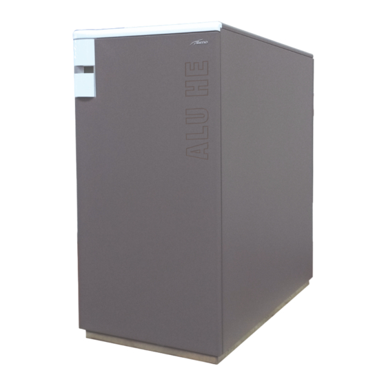
Servizio Tecnico Sime o da Personale Professionalmente Qualificato. Ricevimento del prodotto Gli apparecchi Sime ALU HE vengono forniti in collo unico, protetti da un sacco di nylon, posti su pallet in legno. Fig. 13 ALU HE... -
Page 25: Locale D'installazione
Esempio con durezza acqua di 25°F: (20/25) x 20 = 16 l/kW Quando le caldaie ALU HE vengono installate su impianti vecchi Se le caratteristiche dell'acqua sono diverse da quelle indicate, o da rimodernare, è consigliato verificare che: è... -
Page 26: Collegamenti Idraulici
AVVERTENZA Collegamenti idraulici – È consigliato prevedere un gruppo di neutralizzazione Le dimensioni degli attacchi idraulici delle caldaie Sime ALU HE della condensa e dare alle tubazioni una pendenza sono riportate di seguito. di almeno 3%. – Prima della prima messa in servizio dell'apparecchio riempire d'acqua il sifone. -
Page 27: Scarico Fumi E Aspirazione Aria Comburente
Scarico fumi e aspirazione aria comburente – Quando la caldaia Sime ALU HE aspira l'aria Le caldaie Sime ALU HE sono di "Tipo B" (B23P) o di "Tipo C", comburente dal locale di installazione questo DEVE stagne, (C43 - C 53 - C63 - C 83) in base al tipo di installazione ESSERE DOTATO di aperture di aerazione realizzate da realizzare. -
Page 28: 5.11.1 Lunghezze Massime Dei Condotti
Accessori opzionali aspirazione ALU HE 200 ALU HE 80 Descrizione Diametro Ø 80 Diametro Ø 100 (mm) (mm) Curva a 90° M-F (6 pz.) 8077410 Curva a 90° M-F (con presa 8077407 prelievo) Curva a 90° M-F 8077408 (coibentata) Prolunga L. 1000 mm (6 8077309 pz.) -
Page 29: Collegamenti Elettrici
Collegamenti alla scheda elettronica 5.12 Collegamenti elettrici Le caldaie Sime ALU HE necessitano dei collegamenti di seguito riportati che devono essere effettuati dall’installatore o da personale 49 50 professionalmente qualificato. Parte dei collegamenti arrivano alla morsettiera MC e parte ai connettori della scheda elettronica. -
Page 30: 5.12.1 Sonda Esterna
5.12.1 Sonda esterna Per l’installazione: – rimuovere il coperchio La caldaia è predisposta per il collegamento ad una sonda di – fissare la sonda alla parete utilizzando 2 tasselli rilevamento della temperatura esterna e può funzionare così a – effettuare i collegamenti elettrici. temperatura scorrevole. -
Page 31: Schemi Idraulici Di Principio
5.13 Schemi idraulici di principio Schema idraulico totale LEGENDA: Sonda esterna Termostato ambiente attivazione caldaia Mandata caldaia Ritorno caldaia Gruppo sicurezze INAIL (solo per Italia) Separatore idraulico Pompa circuito primario Neutralizzatore di condensa Sonda mandata cascata Termostato ambiente di zona Relè... - Page 32 Schema idraulico riscaldamento Kit Zona Mix 1 Kit Zona Mix 2 cod. 8092275 cod. 8092276 VMIX 1 VMIX 2 P MIX 1 P MIX 2 NOTA: Possono essere gestiti fino a due impianti MIX, o due gruppi di impianti MIX, installando gli accessori opzionali KIT ZONA MIX 1 (cod.
- Page 33 Schema idraulico con bollitore dopo il separatore idraulico Kit Zona Mix 1 cod. 8092275 VMIX 1 P MIX 1 Schema idraulico con bollitore prima del separatore idraulico Kit Zona Mix 1 cod. 8092275 VMIX 1 PMIX 1 LEGENDA: Sonda esterna Termostato ambiente di Termostato ambiente zona...
- Page 34 Schema idraulico riscaldamento a pavimento Kit Zona Mix 1 cod. 8092275 VMX1 PMIX 1 VZ 1 VZ 2 LEGENDA: Sonda esterna Neutralizzatore di Kit Zona Mix 1 Termostato ambiente condensa VMIX 1 Valvola miscelatrice impianto attivazione caldaia Sonda mandata cascata MIX 1 Mandata caldaia Relè...
-
Page 35: Riempimento E Svuotamento
5.14 Riempimento e svuotamento 5.14.1 Operazioni di RIEMPIMENTO Le caldaie Sime ALU HE NON prevedono il dispositivo di riempimento caldaia/impianto, e il rubinetto di svuotamento. Di conseguenza devono essere previsti, in installazione, montati nei punti più comodi per l'installatore. Prima di effettuare le operazioni di seguito descritte verificare che l’interruttore generale dell’impianto sia posizionato su... -
Page 36: Messa In Servizio
MESSA IN SERVIZIO AVVERTENZA Operazioni preliminari – Quando il display non è retroilluminato (spento) la prima pressione di ogni tasto funzionale serve per Prima di mettere in servizio l'apparecchio verificare che: retroilluminarlo (accenderlo). – il tipo di gas sia quello per cui e stato predisposto l'apparecchio –... -
Page 37: Lista Parametri
Lista parametri I parametri PAR 01 e PAR 02 sono impostati in fabbrica secondo ALU HE la tabella a lato. PAR 01 PAR 02 PAR 01 PAR 02 È VIETATO Selezionare impostazioni diverse da quelle di tabella perché possono generare gravi malfunzionamenti della caldaia. -
Page 38: Segnalazione Guasto/Anomalia
Unità di Tipo N° Descrizione Range Passo Default misura SANITARIO - RISCALDAMENTO Tset Minima Zona 1 Riscaldamento Par 64 OEM .. Par 21 °C Tset Massima Zona 1 Riscaldamento Par 20 .. Par 65 OEM °C Pendenza Curva Riscaldamento Zona 1 3...40 3...40 Tset Minima Zona 2 Riscaldamento Par 64 OEM .. -
Page 39: Codici Anomalie / Guasti
(1) della valvola gas e collegare un manometro Codici anomalie / guasti VALVOLE GAS Tipo N° Descrizione Anomalia Pressostato Aria ALU HE 116 ALU HE 80 Bassa Pressione Acqua Impianto Alta Pressione Acqua Impianto Anomalia Sonda Mandata Caldaia Mancata rilevazione fiamma Apertura Termostato Sicurezza oppure Anomalia... - Page 40 Effettuare eventuali altre misurazioni necessarie. IMPORTANTE La valvola gas della ALU HE 80 è dotata di DUE viti di regolazione della potenza Massima – la vite (2) per una regolazione "grossolana" – la (3) per una regolazione "fine".
-
Page 41: Visualizzazione Dati Di Funzionamento
Visualizzazione dati di funzionamento Una volta che la caldaia è in funzione e possibile, per il tecnico abilitato, visualizzare i dati di funzionamento. Per accedere alle informazioni premere il tasto . Sul display viene visualizzata la prima informazione. Ad ogni pressione di questo tasto si passa all’informazione successiva. - Page 42 18. Visualizzazione valore sonda ritorno riscaldamento (SR) 29. Visualizzazione comando chiusura valvola con schedino ZONA MIX 2 (rispettivamente ON e OFF) 30. Visualizzazione valore temperatura sonda solare 19. Visualizzazione valore sonda collettore cascata con schedino solare 31. Visualizzazione valore temperatura sonda solare 20.
-
Page 43: Cambio Del Gas Utilizzabile
Personale Professionalmente Qualificato. – attivare la Funzione spazzacamino, seguendo la procedura descritta nel paragrafo specifico. Le caldaie Sime ALU HE modelli 80 , 116 , 160 e 200 vengono fornite per funzionamento con gas G20, ma possono funzionare AVVERTENZA anche con gas G31. -
Page 44: Manutenzione
MANUTENZIONE funzionamento sicuro, efficiente regolare dell'apparecchio, Legislazione vigente prevede Responsabile dell'Impianto incarichi Tecnico Professionalmente Qualificato affinché provveda, con periodicità , alla sua manutenzione. ANNUALE Fig. 36 AVVERTENZA Prima di effettuare le operazioni di seguito descritte: Fig. 37 – posizionare l'interruttore generale dell'impianto su "OFF"... -
Page 45: Pulizia Del Corpo Caldaia
– Svitare i dadi (12) e rimuovere le portine di ispezione (13) e le guarnizioni (14) – utilizzare uno scovolo adatto alla pulizia meccanica dei condotti del corpo caldaia, (es. accessorio (15) Sime cod. 6077930). Può essere usato un prodotto chimico purché adatto a corpi in alluminio funzionanti a condensazione (es. -
Page 46: Collegamenti Pressostato Aria E Sifone
7.2.6 Collegamenti pressostato aria e sifone Manutenzione straordinaria I tubetti in silicone dei pressostati aria (1) e sifone (2), nel caso Nel caso di sostituzione della scheda elettronica o della valvola sia stato necessario scollegarli, DEVONO essere ricollegati È OBBLIGATORIO IMPOSTARE I PARAMETRI come descritto come illustrato in figura: al paragrafo specifico "Visualizzazione e impostazione –... -
Page 47: Eventuali Anomalie E Rimedi
Eventuali anomalie e rimedi LISTA ALLARMI ANOMALIE/GUASTI Visualizzazione sul Tipo di anomalia o guasto Causa Rimedio display Errato cablaggio sul pressostato aria - Controllare il corretto cablaggio e i tubetti del Tubetti dal pressostato aria pressostato aria Anomalia pressostato aria scollegati o rotti - Controllare se il condotto dell'aria è... - Page 48 Visualizzazione sul Tipo di anomalia o guasto Causa Rimedio display La sonda di mandata dell’impianto Anomalia sonda di Mix è aperta o cortocircuitata. - Verificare la sonda e i suoi collegamenti allo schedino mandata zona miscelata La caldaia continua il normale - Verificare il funzionamento dello schedino funzionamento La sonda ritorno riscaldamento (SR)
- Page 51 – The appliance must be used as intended by Sime that they are supervised or have been instructed who is not responsible for any damage caused to...
- Page 52 ALU HE 280 - (G20) 8115751 DESCRIPTION OF THE APPLIANCE COMPLIANCE TABLE OF CONTENTS Our company declares that ALU HE boilers comply with the following directives: – Gas Appliances Directive 2009/142/EC – Low Voltage Directive 2014/35/EU INSTALLATION AND SERVICING – Electromagnetic Compatibility Directive 2014/30/EU –...
- Page 53 2002/96/CE) ........57 Fault / malfunction codes......56 SIME remote control connection (optional accessory) 57...
-
Page 54: Using The Boiler Alu He
Control panel ON/OFF BUTTON The control panel allows all operators to make all adjustments necessary to manage Sime ALU HE boilers and connected ON = Boiler has electric power. systems. OFF = Boiler has electric power but is not available for operation. -
Page 55: Start-Up
Start-up Adjusting the delivery temperature The control panel on ALU HE boilers lets you manually adjust the 1.2.1 Preliminary checks delivery temperature on two temperature levels by choosing the Commissioning of the ALU HE boiler must be carried out by best ones for the systems managed (e.g. -
Page 56: Fault / Malfunction Codes
In the case of all other errors, before repairing the fault, it is Shown on display Type of malfunction or fault recommended, as a precautionary measure, that you: – disconnect the appliance from the mains power by setting the main switch to "OFF" Parasite flame fault –... -
Page 57: Sime Remote Control Connection (Optional Accessory)
MAINTENANCE SIME remote control connection (optional accessory) The boiler is ready for connection to a SIME remote control. Adjustments When the remote control is connected, the boiler display shows: For the appliance to operate correctly and efficiently it is recommended that the system manager calls upon the services of a Professionally Qualified Technician to carry out ANNUAL maintenance. - Page 59 DESCRIPTION OF THE APPLIANCE TABLE OF CONTENTS Structure ........63 DESCRIPTION OF THE APPLIANCE Technical features.
-
Page 60: Description Of The Appliance
Sime ALU HE circulation at the end of which they stop and wait for the next auxiliary sensor and to the Sime Home or Sime Home Plus remote request for heat. controls. They can manage direct systems or direct systems and two mixed systems (or two groups of mixed systems connected 4.1.2... -
Page 61: Check And Safety Devices
Check and safety devices Identification The ALU HE boilers are equipped with the following check and The ALU HE boilers can be identified by means of: safety devices: this is located on the outside of the Packaging label: – thermal safety thermostat 98°C with automatic reset packaging and provides a code, the serial number of the –... -
Page 62: Technical Data Plate
4.3.1 Technical Data Plate NAME APPLIANCE TYPE SERIAL NUMBER CODE YEAR OF MANUFACTURE N° PIN WATER CONTENT IN BOILER TYPE OF GAS TYPE OF GAS MAX HEAT INPUT MIN HEAT INPUT MAX USEFUL OUTPUT (80-60°C) MIN USEFUL OUTPUT (80-60°C) MAX USEFUL OUTPUT (50-30°C) MIN USEFUL INPUT (50-30°C) MAX OPERATING TEMPERATURE MAX OPERATING PRESSURE... -
Page 63: Structure
Structure Front panel Gas valve Pressure transducer Pressure gauge fitting Return sensor (SR) System return manifold Boiler drain valve Foot Condensate siphon outlet Condensate collection tank Boiler return Smoke outlet fitting Combustion air inlet Boiler body Gas supply pipe Boiler delivery Delivery sensor System delivery manifold Top panel... -
Page 64: Technical Features
Technical features ALU HE DESCRIPTION CERTIFICATIONS AT - CH - CZ - ES - GB - GR - IE - PT - SI - SK - IT - LT - DK Country of intended installation EE - FI - LV - NO - SE - BE - CY NL - HU... -
Page 65: Main Water Circuit
Main water circuit Fig. 7 KEY: Delivery sensor M Boiler delivery R Boiler return Gas valve G Gas supply Water pressure transducer Sc Condensate outlet Return sensor (SR) Boiler drain valve Condensate siphon outlet Min. gas pressure switch Safety thermostat... -
Page 66: Sensors
The table below shows the minimum water flow rate required – DO NOT operate the pumps without any water. for each boiler. – The pumps chosen must have a consumption ALU HE suitable for the fuse installed on the electrical panel DESCRIPTION (4AT). -
Page 67: Control Panel
4.10 Control panel The control panel allows all operators to make all adjustments DESCRIPTION OF COMMANDS necessary to manage Sime ALU HE boilers and connected ON/OFF BUTTON systems. ON = Boiler has electric power. OFF = Boiler has electric power but is not available for operation. -
Page 68: Wiring Diagram
4.11 Wiring diagram GREEN BLUE GREEN BLACK BLACK GREEN BLACK BLUE BLUE GREEN BLUE CD. 63228900 49 50 SB/SA CN12 CN13 CN14 CN11 CN10 CN18 BLUE 0...10VDC BLACK BROWN BLUE KAPI BLUE BLUE BROWN BROWN RS485 BLUE Cascade delivery probe Flame detection electrode Electrode on Min. -
Page 69: 4.11.1 Rs 485 Board
4.11.1 RS 485 board The RS485 board is provided as standard and is factory installed on every boiler. It is needed for the boilers to communicate with one another , when they are installed in a cascade, or to communicate externally, when a single boiler is installed. - Page 71 INSTALLATION AND SERVICING INSTRUCTIONS TABLE OF CONTENTS INSTALLATION MAINTENANCE Receiving the product ......72 External cleaning.
-
Page 72: Installation
The appliance must be installed by the Sime Technical Service only, or by a qualified professional. Receiving the product Appliances Sime ALU HE are supplied in a single package, protected by a nylon cover, placed on wooden pallets. Fig. 13... -
Page 73: Installation Room
Example with water hardness of 25°F: (20/25) x 20 = 16 l/kW When ALU HE boilers are installed on old systems or systems requiring updating, it is recommended the installer checks that: If the water characteristics are different from those indicated, it –... -
Page 74: Plumbing Connections
CAUTION Plumbing connections – It is recommended that a condensate neutralising The dimensions of the water fittings of Sime ALU HE boilers are unit be provided and the pipework should have a given below. downward angle of at least 3%. -
Page 75: Smoke Outlet And Combustion Air Inlet
WARNINGS 5.11 Smoke outlet and combustion air inlet – When the Sime ALU HE boiler takes in combustion boilers are "Type B" (B23P) or "Type C", sealed, Sime ALU HE air from the place of installation it MUST BE (C43 - C 53 - C63 - C 83) depending on the type of installation. -
Page 76: 5.11.1 Maximum Duct Lengths
Inlet optional accessories ALU HE 200 ALU HE 80 Description Diameter Ø 80 Diameter Ø 100 (mm) (mm) 90° curve M-F (6 pieces) 8077410 90° curve M-F (with take- 8077407 off point) 90° curve M-F (insulated) 8077408 Extension W. 1000 mm (6... -
Page 77: Electrical Connections
Connections to electronic circuit board 5.12 Electrical connections boilers require the connections given below which Sime ALU HE must be carried out by the installer or by professionally qualified 49 50 personnel. Some of the cabling is to the MC terminal board and some to the electronic circuit board connectors. -
Page 78: 5.12.1 External Sensor
5.12.1 External sensor For installation:: – remove the cover The boiler is prearranged for connection to an external air – attach the sensor to the wall using 2 plugs temperature sensor and can operate with a sliding temperature. – make the electrical connections. This means that the delivery temperature sent to the boiler can vary on the basis of the external temperature depending on the climatic curve selected from those shown in the diagram (Fig. -
Page 79: Main Hydraulic Diagrams
5.13 Main hydraulic diagrams Full hydraulic diagram KEY: External sensor Air thermostat for boiler activation Boiler delivery Boiler return INAIL safety unit (Italy only) Hydraulic separator Primary circuit pump Condensate neutraliser Cascade delivery probe Zone ambient thermostat Zone relays Direct zone pump Mix 1 Zone pump VMIX 1 MIX 1 system mixer valve... - Page 80 Heating hydraulic diagram Mix 1 Zone kit Mix 2 Zone kit code 8092275 code 8092276 VMIX 1 VMIX 2 P MIX 1 P MIX 2 NOTE: Up to two MIX systems, or two groups of MIX systems, can be managed by installing the optional accessories MIX 1 ZONE KIT (code 8092275) and MIX 2 ZONE KIT (code 8092276).
- Page 81 Hydraulic diagram with tank after hydraulic separator Mix 1 Zone kit code 8092275 VMIX 1 P MIX 1 Hydraulic diagram with tank before hydraulic separator Mix 1 Zone kit code 8092275 VMIX 1 PMIX 1 KEY: External sensor Zone ambient thermostat Air thermostat for boiler Zone relays Storage tank pump...
- Page 82 Underfloor heating hydraulic diagram Mix 1 Zone kit code 8092275 VMX1 PMIX 1 VZ 1 VZ 2 KEY: External sensor Condensate neutraliser Mix 1 Zone pump Air thermostat for boiler Cascade delivery probe VMIX 1 MIX 1 system mixer valve activation Zone relays PMIX 1...
-
Page 83: Refilling Or Emptying
5.14 Refilling or emptying 5.14.1 REFILL operations Sime ALU HE boilers DO NOT have a device to fill the boiler/ system and an emptying tap. Therefore these must be provided, during installation, assembled in the most convenient places for the installer. -
Page 84: Commissioning
COMMISSIONING CAUTION Preliminary operations – When the display is not backlit (off), the first press on each function button serves to backlight it (turn Before commissioning the appliance, check that: it on). – the type of gas is correct for the appliance –... -
Page 85: List Of Parameters
List of parameters The parameters PAR 01 and PAR 02 are factory set according to ALU HE the table shown here to the right. PAR 01 PAR 02 PAR 01 PAR 02 IT IS FORBIDDEN to select settings other than those shown in the table as this could generate a serious boiler malfunction. -
Page 86: Fault/Error Message
Type Description Range Step Default DOMESTIC HOT WATER - HEATING Minimum Tset Zone 1 Heating Par 64 OEM .. Par 21 °C Maximum Tset Zone 1 Heating Par 20 .. Par 65 OEM °C Heating Curve Grade Zone 1 3...40 3...40 Minimum Tset Zone 2 Heating Par 64 OEM .. -
Page 87: Fault / Malfunction Codes
(1) on the gas valve and connect a pressure gauge Fault / malfunction codes GAS VALVE Type Description Air pressure switch fault ALU HE 116 ALU HE 80 Low water pressure in system High water pressure in system Boiler delivery probe fault No flame detection... - Page 88 Take any other necessary readings. IMPORTANT The gas valve on the ALU HE 80 is equipped with TWO screws to adjust the maximum power – screw (2) for an approximate adjustment – screw (3) for a finely tuned adjustment.
-
Page 89: Operating Data Display
Operating data display Once the boiler is operating, a qualified technician can view the operating data. To access the information, press the button. The first piece of information is shown on the display. Each time this button is pressed, the next piece of information is shown. If the button is not pressed, the system exits the function automatically. - Page 90 18. Heating return sensor value (SR) 29. Valve close command with MIX 2 ZONE board, respectively ON and OFF 30. Solar sensor temperature with solar board 19. Cascade manifold sensor value 31. Solar sensor temperature with solar board 20. Mixed system delivery probe value with MIX 1 ZONE board 32.
-
Page 91: Gas Conversion
If the gas supply is changed from G20 to G31, mark the G31 gas. box on the TECHNICAL DATA PLATE. Marking is OBLIGATORY only for models ALU HE 80 , If the gas used is changed, run the full appliance “Commission , 160 and 200 . -
Page 92: Maintenance
MAINTENANCE For the appliance to operate safely, correctly and efficiently current legislation requires that the System Manager calls upon the services of a Professionally Qualified Technician to carry out maintenance. ANNUAL Fig. 36 CAUTION Before carrying out the interventions described below:: Fig. -
Page 93: Cleaning Boiler Body
(14) – Use a rod suitable for mechanically cleaning the boiler body ducts (e.g. Sime accessory (15) code 6077930). A chemical product can be used provided it is suitable for aluminium bodies working by condensation (e.g. Bekaert TAB 2/2000). -
Page 94: Connecting The Air Pressure Switch And Siphon
7.2.6 Connecting the air pressure switch and siphon Unscheduled maintenance The silicon tubes on the air pressure switches (1) and siphon If you replace the electronic circuit board or gas valve YOU MUST (2) MUST be reconnected, where it was necessary to disconnect SET THE PARAMETERS as described under "Parameter setting them, as shown in the figure: and display". -
Page 95: Possible Faults And Solutions
Possible faults and solutions LIST OF MALFUNCTION/FAULT ALARMS Type of malfunction or Shown on display Cause Solution fault Incorrect wiring on air pressure switch - Check correct wiring and air pressure switch tubes Tubes from air pressure switch Air pressure switch fault - Check that the air duct is free of obstructions disconnected or damaged - Check that the smoke duct is free of obstructions... - Page 96 Type of malfunction or Shown on display Cause Solution fault The Mix system's delivery sensor Delivery sensor fault mixed - Check the sensor and its board connections is open or has short-circuited. The zone - Check operation of the board boiler continues normal operation The return sensor (SR) is open Return sensor (SR) fault...
- Page 100 Fonderie Sime S.p.A - Via Garbo, 27 - 37045 Legnago (Vr) Tel. +39 0442 631111 - Fax +39 0442 631292 - www.sime.it Fonderie SIME S.p.A. si riserva di variare in qualunque momento e senza preavviso i propri prodotti nell’intento di migliorarli senza pregiudicarne le caratteristiche essenziali.
Need help?
Do you have a question about the ALU HE and is the answer not in the manual?
Questions and answers