
Related Manuals for APV GRASSLAND PRO HARROW


Summary of Contents for APV GRASSLAND PRO HARROW
- Page 1 GRASSLAND PRO HARROW GP 600 M2 OPERATING MANUAL PLEASE READ CAREFULLY BEFORE INITIAL OPERATION Translation of the original operating manual Version: 2.3 EN; item number: 00602-3-775...
- Page 2 TABLE OF CONTENTS EC DECLARATION OF CONFORMITY ..................4 UK CONFORMITY ASSESSED ...................... 5 IDENTIFICATION OF THE IMPLEMENT ..................6 SERVICE ............................6 WARRANTY ........................... 7 Warranty activation ......................7 SAFETY INFORMATION ........................ 7 Intended use ........................7 General safety-related instructions and accident prevention regulations ......8 Mounted implements ......................
- Page 3 16.2 Storage of the implement ....................35 16.3 Disposal ..........................36 CROP CULTIVATION TIPS FOR USE OF THE GRASSLAND PRO HARROW ......36 ACCESSORIES ..........................37 18.1 Equipment kit for operation on public traffic areas .............. 37 18.1.1 Compressed air system ..................... 37 18.1.2 Wheel chocks ........................
- Page 4 Relevant EC Directives: Directive for machinery – Machinery Directive 2006/42/EC For the planing, design, construction and marketing of the "Grassland Pro Harrow GP 600 M2" mounted implement, the following harmonised European standards were applied in addition to the Directives, in particular: EN ISO 12100:2010 –...
- Page 5 Relevant EC Directives: Directive for machinery – Machinery Directive 2006/42/EC For the planing, design, construction and marketing of the "Grassland Pro Harrow GP 600 M2" mounted implement, the following harmonised European standards were applied in addition to the Directives, in particular: EN ISO 12100:2010 –...
- Page 6 IDENTIFICATION OF THE IMPLEMENT The Grassland Pro Harrow can be clearly identified by the following information on the type plate: Designation Model Vehicle class Vehicle ID number Position of the type plate The type plate is located on the right of the centre frame (see Figure 1).
- Page 7 WARRANTY ACTIVATION Every APV implement must be registered immediately after delivery. The registration activates the claim for warranty services and APV can guarantee the best service. To activate the warranty for your implement, simply scan the QR code with your smartphone - you will then be taken directly to the service area on our website.
- Page 8 GENERAL SAFETY-RELATED INSTRUCTIONS AND ACCIDENT PREVENTION REGULATIONS The warning and information signs applied to the implement provide important instructions for safe operation. These may not be removed in any case, observe them for the sake of your own safety! ...
- Page 9 With initial use of the implement, the operator/user confirms that they have read and fully understood this operating manual. When mounting the implement, the operator/user must connect the Grassland Pro Harrow to the tractor by means of a mechanical connection (ensured by the lower link). ...
- Page 10 MOUNTED IMPLEMENTS Only APV implements and accessories may be mounted on the implement. Do not stand between the tractor and the implement when actuating the external controls for the three- point mounting! ...
- Page 11 Replacing components that cannot be removed with tools such as a screwdriver or wrench may only be replaced by qualified specialist personnel from an appropriately authorised company or by APV Customer Service. The implement must be checked regularly by the operator (before every use) for any fractures and cracks, leaks, chafe marks, loose bolts and connections, vibrations and to ensure it functions correctly.
- Page 12 The platform kit must only be used as a maintenance walkway. An ascent must be established conforming to the standards. This ascent is available from APV. When not in use, the steps must be folded up and secured.
- Page 13 6.8.1 DANGER AREAS DURING IMPLEMENT OPERATION Figure 3...
- Page 14 6.8.2 DANGER AREAS WHEN FOLDING AND UNFOLDING Figure 4 RESIDUAL HAZARDS Residual hazards are special hazards when working with the implement, which cannot be eliminated despite safety-compliant design. Residual hazards are often not obvious and can be a source of possible injuries or health risks. 6.9.1 DANGER FROM MECHANICAL SYSTEMS There is a risk of accidents due to crushing, cutting and impacts with body parts...
- Page 15 6.9.3 DANGERS ARISING FROM OPERATION During operation, there is a risk of injury to body parts, particularly the face, due to stones and clods of soil being flung up. INFORMATION SIGNS / HAZARD LABELS Pay special attention to the stickers on the implement, as they warn you of specific dangers! CAUTION! Keep information signs and hazard labels clean If hazard labels or information signs are becoming or are already detached, they need to be replaced...
- Page 16 Information sign (symbolic representation) Order number 00603-3-687 00600-3-138 00600-3-163 After a short period of These stickers indicate Labelling of the lubrication Explanation operation, re-tighten all the tyre inflation pressure. points. bolts and nuts. Information sign Order number 00602-3-119 00600-3-139 00601-3-658 Loading hooks.
- Page 17 HAZARD LABELS Information sign Order number 00604-3-648 00603-3-664 00602-3-294 Caution, crushing area! Caution, do not climb onto Never reach into the Always lift the implement Explanation the implement! crushing danger zone as slowly off the ground. long as the parts can still Risk of rolling over! move! Information...
- Page 18 PLACEMENT OF THE HAZARD LABELS AND OTHER SIGNS The following figures show the arrangement of the hazard labels and other signs on the implement. Figure 5 Figure 6 Figure 7 Figure 8 Figure 9 Figure 10...
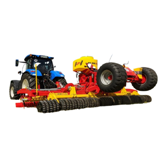
- Page 19 Figure 13 Thanks to its robust and compact design, the Grassland Pro harrow is ideal for new seeding, reseeding, and controlling weeds on grassland. The spring-mounted levelling plate ensures optimal distribution and levelling of molehills, manure, slurry, and cow pats.
- Page 20 MOUNTING AND DISMOUNTING THE IMPLEMENT 8.2.1 GENERAL INFORMATION The tractor tyre pressure must be selected as specified by the tractor manufacturer. Under difficult operating conditions, additional wheel weights can be useful. Comply with the information provided by the tractor manufacturer. ...
- Page 21 Connect the lighting and electrical cables (if present). Test the lighting function. Hydraulic connections for roller (yellow dust caps) Hydraulic connections for chassis (blue dust caps) Hydraulic connections for Pneumatic Seeder and pressureless return (if present) Implement cables Pneumatic Seeder (if present) Hydraulic connections for folding (red...
- Page 22 CAUTION! Prior to uncoupling, you must check again to ensure that the mechanical folding lock is engaged. CAUTION! Comply with the sequence for locking the pneumatic brake system ! First uncouple the red brake line, then the yellow brake line. This is precisely the reverse of the sequence described for coupling the implement.
- Page 23 FOLDING FROM WORKING POSITION INTO TRANSPORT POSITION The hydraulic cylinders for depth setting of the roller must be in the maximum possible retracted position. When using the 410 mm toothed ring roller, the total length of the clips that are used on the roller cylinders must not exceed 100 mm.
- Page 24 8.5.2 ADJUSTING THE SERIES OF HOLES In addition to depth setting, the aggressiveness of each individual tine row can also be changed individually. This makes it possible to compensate for the different levels of wear of the individual tines. For series of holes adjustment, the bolts for the tine sections are inserted either in a higher / more forward or lower / more rearward hole (see Figure 23).
- Page 25 1 Crank 2 Locking pin 3 Shear bolt 4 Levelling plate Figure 24 Figure 25 Figure 26 CAUTION! Only operate the crank with one hand; two-hand operation poses a considerable risk of injury (hand or finger injuries). The crank has a slip safeguard for better handling and transmission of force.
- Page 26 NOTE! It must be noted that by removing the roller, uniform depth control can no longer be ensured for the harrow units. For this reason, feeler wheels must always be installed when the rollers are removed. CAUTION! The rollers may only be installed or removed when the feeler wheel mounting kit is used (see Point 18.9).
- Page 27 CAUTION! For every folding process of the side frames, the operator must visually inspect the folding lock. Road transport of the implement is only permitted if the folding lock is engaged. TIP! For easier release of the folding lock, briefly apply pressure to the folding cylinder. This fully extends the folding cylinder and the side frame is completely lifted again.
- Page 28 ASSISTANCE IN CASE OF MALFUNCTIONS PROCEDURE IN CASE OF MALFUNCTIONS OR ERRORS If errors or untypical behaviour occur during start-up of the implement, please contact our Service Centre, see section 4 Service. MAINTENANCE AND CARE To maintain the implement in good condition even after a long service life, the following instructions must be observed: 10.1 GENERAL MAINTENANCE INSTRUCTIONS ...
- Page 29 After the first 10 operating hours and subsequently every 50 operating hours, the hydraulic units, hoses and couplings as well as tube lines must be checked for leaks and the bolted connections must be tightened if necessary. Before every operation, check the hydraulic hose lines for wear, damage and ageing. Damaged or faulty parts must be immediately replaced.
- Page 30 10.4 TINE SAFETY As standard, the GP series is equipped with a tine safety that prevent loss of the 12 mm tines by means of a rope. It protects the tines so that they do not get lost on the pasture or on the field. This also prevents damage to other implements, e.g.
- Page 31 Figure 38 Figure 37 Figure 39 Figure 40 Figure 41 Figure 42 10.6 REPAIRS AND SERVICE In case of failure or damage to the implement, please contact the manufacturer. The contact data can be found in chapter 3.
- Page 32 INFORMATION ON NATURE CONSERVATION AND ENVIRONMENTAL PROTECTION Energy-efficient use The tines of the implement should not penetrate into the field deeper than necessary. By doing so, the towing vehicle is not unnecessarily strained and fuel can be saved. Recyclable raw materials during disposal Many parts of the implement are made of steel or spring steel (such as the centre frame, side frames, etc.) and can be removed and recycled by a waste disposal company.
- Page 33 POSSIBLE COMBINATIONS WITH A PNEUMATIC SEEDER PS200 H PS300 H PS500 H PS800 H Dimensions HxWxD GP weight Dimension HxWxD [cm] [kg] [cm] Delivery Road transport Without 127x105x17 100x70x110 110x77x150 117x80x125 Without Without and with PS 500 GP 600 toothed 350 x 299 x 575 ~ 4700 Can be combined with PS mounting kit...
- Page 34 Lighting equipment of the towing vehicle may not be hidden by the implement; otherwise, they must be installed on the mounted implement. The steering capacity of the tractor must not be impeded or reduced by the mounted implement! ...
- Page 35 LIGHTING CIRCUIT DIAGRAM Legend: Right 12 V plug, 7-pin Rear light, right Turn signal Rear light Brake light Left Rear light, left Brake light Rear light Turn signal Plug and cable assignment Desi Colour Function Yellow Turn signal, left Figure 43 White Earth Green...
- Page 36 GRASSLAND PRO HARROW Seedbed preparation is always required before reseeding. This procedure is optimally accomplished with the Grassland Pro Harrow with 4 rows of tines. Together with the reconsolidation by a roller, five working procedures are accomplished in one field pass.
- Page 37 ACCESSORIES 18.1 EQUIPMENT KIT FOR OPERATION ON PUBLIC TRAFFIC AREAS This kit is required to comply with all requirements for operation on public traffic areas. The kit contains the following components: Dual-circuit pneumatic brake system Wheel chocks Tine sections cover ...
- Page 38 Note that with a vented trailer brake valve, the service brake is not active, therefore the forward speed imposed by the country-specific regulations for unbraked, towed agricultural machinery must be complied with. 18.1.1.1 DRAINING A drain valve is provided on the underside of the reservoir. It must be actuated weekly throughout the year and daily in the winter.
- Page 39 18.1.4 LIGHTING WITH WARNING SIGNS (ON BOTH SIDES) Warning signs with lighting are available as accessories for the Grassland Pro Harrow. These signs are required when the implement is transported in road traffic. The lighting / warning signs are also available separately, the...
- Page 40 18.1.5 MUDGUARD The mudguards are also available separately, the following order number can be used for this: Order number: Tyre dimension 500/50-17": 06028-2-247 Tyre dimension 400/60-15.5" and 12.5"/80-18": 06028-2-216 Figure 54: Symbolic image 18.1.6 ANTI-THEFT DEVICE The anti-theft device is also available separately, the following order number can be used for this: Order number: 06028-2-262 18.2 MOUNTING KIT FOR PS200 - 500...
- Page 41 18.5 PLATFORM KIT A suitable platform kit is available as an accessory for easier maintenance of the PS 200 – PS 800 Pneumatic Seeder. Please note that it must be mounted in compliance with the standards. Order number: 06028-2-275 Figure 58 18.6 CHANGEOVER VALVE FOR OPERATING TWO HYDRAULIC FUNCTIONS The changeover valve enables connection of the...
- Page 42 TIP! Before driving off for the first time, calibrate the speed on the Control Box 5.2. Figure 61 18.9 FEELER WHEEL MOUNTING KIT This kit is required if you want to mount or dismount the roller of the GP. It consists of: ...
- Page 43 Please keep your product number / serial number at hand. You can also view our online spare parts catalogue on our website www.apv.at the Service area. If you have any questions regarding spare parts or your order, our Customer Service (see point 4 Servicefor contact data) is also happy to assist you.
- Page 44 APV – Technische Produkte GmbH Zentrale: Dallein 15 AT - 3753 Hötzelsdorf Tel.: +43 2913 8001 office@apv.at www.apv.at...
Need help?
Do you have a question about the GRASSLAND PRO HARROW and is the answer not in the manual?
Questions and answers