
Related Manuals for APV 6.2


Summary of Contents for APV 6.2
- Page 1 Translation of the original operating manual Before commissioning Read the "Quick start" menu item carefully! From serial number: 6.2-01000 – Version: 02/2018, V1.2 Order no.: 00601-3-151...
- Page 2 Quality for Professionals It may NOT seem inconvenient and unnecessary to read and observe the operating instructions. It is not enough to hear and see from others that an implement is good, and then to buy it and believe that everything takes care of itself. The person concerned would then not only cause damage to himself, but also make the mistake of assuming that the cause of any problems is due to the implement, instead of himself.
-
Page 3: Table Of Contents
Quality for Professionals Table of contents Warranty ........................4 Initial commissioning ....................5 Scope of delivery and attachment ................5 Electrical connection ....................6 Plug overview ......................7 Control box ......................8 Initial operation menu (basic settings menu) ............9 Menu structure ......................11 Start menu ......................11 Work menu ......................12... -
Page 4: Warranty
Quality for Professionals Warranty Please check the implement for any transport damage immediately upon receipt. Later claims regarding transport damage can no longer be considered. We provide a one-year factory warranty as of the date of delivery (your invoice or the delivery slip serve as a warranty certificate). -
Page 5: Initial Commissioning
Quality for Professionals Initial commissioning Scope of delivery and attachment Control box RAM-C holding Power cable RAM-C Mounting ball Fig.: 1 • Fasten the control box with the standard supplied RAM bracket. • To do so, install the mounting ball anywhere in the cab. •... -
Page 6: Electrical Connection
Quality for Professionals Electrical connection Plug the supplied cable directly into the 3-pin power socket on the tractor. The other end is connected to the control box. The fuse (30 A) is located on the bottom side of the control box. Stow the excess cable in the driver's cab to avoid pinching. -
Page 7: Plug Overview
Quality for Professionals Plug overview Fig.: 3 USB port 12-pin plug 30 A fuse 3-pin plug 9-pin DSuc plug 6-pin plug 7-pin signal cable (for standard socket) Lifting unit sensor Speed & headland 12-pin plug sensors Wheel sensor Radar sensor GPSa sensor Seeding shaft motor Electrical blower fan... -
Page 8: Control Box
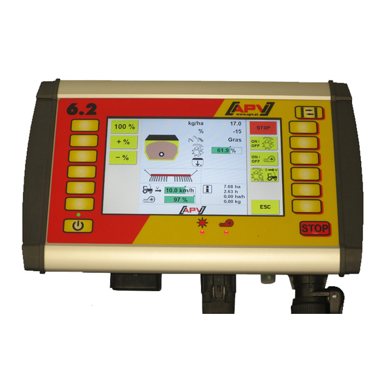
Quality for Professionals Control box Inverting button 6 softkeys 6 softkeys Lights up when Colour display with STOP Lights up when the Is illuminated when the controller is touch operation button seeding shaft is the fan is switched switched on rotating On/Off button Fig.: 4... -
Page 9: Initial Operation Menu (Basic Settings Menu)
Initial operation menu (basic settings menu) For the initial operation or when it was restored to factory setting in the SET menu, the following settings must be entered on your 6.2 control box: Fig.: 5 Select the desired parameter using the +/- buttons, confirm by pressing OK and continue to the next point. - Page 10 Quality for Professionals Select whether a sensor for fan monitoring is installed on your No sensor is installed. A pressure sensor is installed. A speed sensor is installed. Select whether the serial number on your PS800 is greater than 04011-01300. TIP: the serial number is on the rating plate of your PS, which is located on the side of the implement (see Fig.: 6).
-
Page 11: Menu Structure
Quality for Professionals Menu structure Start menu Fig.: 7 This screen appears after the controller has started up. From here, the different menus can be called up. The STOP button is used to immediately turn off all of the motors. The controller switches to the start menu. -
Page 12: Work Menu
Quality for Professionals Work menu Fig.: 8 Description of the button functions With this button, the seeding shaft can be switched on or off. If an electrical blower fan is installed, it will start running automatically. Only then does the seeding shaft also start rotating. With this button, the electric fan can be switched on or off. - Page 13 Quality for Professionals With the 100 % button, you can set the spread rate back to the value determined during calibration. With the +% button, you can increase the spread rate during operation in 5% increments, up to max. 50%. With the -% button, you can reduce the spread rate during operation in 5% increments, up to max.
- Page 14 Quality for Professionals Displays the current forward speed. The black mark shows the forward speed set during calibration. If the forward speed is so high or so low that the required rotational speed of the seed shaft can no longer be maintained, the bar turns red and an alarm sounds (for controller messages see Point...
-
Page 15: Set Menu
Quality for Professionals SET menu Fig.: 9 Description of the button functions Seed library: here, a seed type already saved can be selected. Detailed description under Point 3.3.1. Fill menu: the fill quantity can be entered here. The fill quantity used to calculated the possible remaining distance/area for display in the Work menu. - Page 16 Quality for Professionals Alarm menu: here, the alarm times can be set and the acoustic alarm signal can be deactivated. Details under Point 3.3.6. Empty hopper: by pressing and holding the button for 2 seconds, the emptying procedure is started. CAUTION: before emptying, the calibration lid must be removed and the calibration bag must be attached (see operating manual for the spreader).
-
Page 17: Seed Library
Quality for Professionals Fig.: 10 Seed library In this menu, all of the saved seed types are listed. Seed types can be created and saved by means of a calibration test, see Point 3.3.3. Description of the button functions With the arrow buttons, you can select the desired seed type. By pressing the OK button, you go to the Seed type menu. -
Page 18: Seed Menu
Quality for Professionals Seed menu Fig.: 11 In this menu, all set parameters that were saved at last use of the seed type are displayed. Description of the button functions With the OK button, the seed type is applied and you go to the Work menu. -
Page 19: Seed Info Menu
Quality for Professionals Shows the working width of the implement. Shows the working speed. Shows the used seeding shaft. Shows the seeding shaft speed in %. Seed info menu Fig.: 12 This menu shows a seed type-specific day counter and total counter. The day counter can be reset by pressing and holding the delete button for 2 seconds. -
Page 20: Fill Menu
Quality for Professionals Fill menu Fig.: 13 Here, the current hopper fill level can be entered. This forms the basis for the mathematically possible remaining distance/quantity that is displayed in the Work menu. Description of the button functions With the arrow buttons, you can select the desired parameter. The selected value is changed using the +/- buttons. -
Page 21: Calibration Menu
Quality for Professionals Calibration menu Fig.: 14 In this menu, the parameters required for the calibration test are entered. Description of the button functions With the arrow buttons, you can select the desired parameter. The selected value is changed using the +/- buttons. With the ESC button, you go back one menu level, in this case, to the SET menu. - Page 22 Quality for Professionals Set the working width of your implement here. Note: deduct any overlaps from the working width! Set the forward speed here. If you are working with a speed sensor, enter the average working speed. Here, you can set the used seeding shaft. This is then saved and displayed in the Seed library.
-
Page 23: Perform A Calibration Test
Quality for Professionals Perform a calibration test During calibration, the correct seeding shaft speed is determined for your settings (spread rate, forward speed, ...). A proper calibration is important, as it is the only way to ensure that your desired spread rate is achieved! Proceed as follows: 1. - Page 24 Quality for Professionals 8. When the set calibration time has expired or as soon as you let go of the calibration button, this screen appears. The calculated weight is displayed here. Fig.: 15 9. Now weigh the calibrated seed. 10. Use the +/- buttons to enter the weight of the calibrated seed.
- Page 25 Quality for Professionals 12. The screen with the calibration test results is displayed. Fig.: 16 Explanation of the display elements, see Point 3.3.1.1. 13. With the +/- buttons enter the name of the seed. Option: confirm your entries right away with the OK button and apply the settings in the WORK menu.
-
Page 26: Speed Calibration Menu
Quality for Professionals Fig.: 17 Speed calibration menu In this menu, the forward speed can be calibrated. When using a speed sensor, it is necessary to calibrate the forward speed (except with the GPSa sensor), since the seeding shaft speed is regulated based on the forward speed. Description of the button functions With the arrow buttons, you can select the desired parameter. -
Page 27: Performing The Calibration Test
Quality for Professionals Description of the display elements Displays the currently measured forward speed. Displays the current calibration value for the 7-pin signal cable, the radar sensor, and the GPSa sensor. Displays the current calibration value of the wheel sensor Performing the calibration test There are two methods for calibrating the speed signal of the sensors. - Page 28 Quality for Professionals Automatic calibration With automatic calibration, the calibration value is determined automatically while driving a distance of 100 metres. Proceed as follows: 1. Measure a straight distance of 100 metres and mark the beginning and the end of this distance. 2.
-
Page 29: Save Different Calibration Values
Quality for Professionals Save different calibration values Fig.: 18 In this menu you can save up to five different calibration values. This can be useful when using several tractors or implements with different calibration values. Description of the button functions You can select a memory location with the arrow buttons. -
Page 30: Pre-Metering Menu
Quality for Professionals Pre-metering menu Fig.: 19 In this menu, you can enter the settings for pre-metering. Description of the button functions With the arrow buttons, you can select the desired parameter. The selected value is changed using the +/- buttons. The set value is applied with the OK button. -
Page 31: Alarm Menu
Quality for Professionals Alarm menu Fig.: 20 In this menu, various settings can be entered for the alarms. Description of the button functions With the arrow buttons, you can select the desired parameter. The selected value is changed using the +/- buttons. The set value is applied with the OK button. -
Page 32: Empty Hopper
Quality for Professionals Empty hopper Fig.: 21 In this menu the remaining seed is emptied out of the hopper. The seed shaft runs at 100% and the time is displayed. Description of the button functions With the ESC button, you end the emptying and go back one menu level, in this case, to the SET menu. -
Page 33: Blower Fan Menu
Quality for Professionals Blower fan menu Fig.: 22 In this menu, various settings can be entered for the blower fan speed. The speed of the electrical blower fan, the number of pulses from the speed sensor, and the speed limits for the hydraulic blower fan can be set. -
Page 34: Terminal Menu
Quality for Professionals Terminal menu Fig.: 23 In this menu language, units of measure, brightness and sound volume can be set. Description of the button functions With the arrow buttons, you can select the desired parameter. The selected value is changed using the +/- buttons. The set value is applied with the OK button. -
Page 35: Info Menu
Quality for Professionals Info menu Fig.: 24 In this menu, 3 different trip counters, which can be individually reset, and a total counter are displayed. Description of the button functions With the ESC button, you go back one menu level, in this case, to the Start menu. By pressing and holding the Delete button for 2 seconds, the respective day counter can be reset to zero. -
Page 36: Diagnostic Menu
Quality for Professionals Diagnostic menu Fig.: 25 In this menu, all of the important information for customer service is displayed. This includes the switching states of the sensors, the supply voltage, and the power consumption of the motors. Description of the button functions With the ESC button, you go back one menu level, in this case, to the Start menu. - Page 37 Quality for Professionals In this area, information on the speed sensors is displayed: Current forward speed If the wheel sensor input is used to determine the forward speed, this point is coloured green. If Pin 1 (actual forward speed) or Pin 2 (theoretical forward speed) of the 7-pin DIN signal cable is used to determine the forward speed, the respective point is coloured green.
-
Page 38: Basic Settings Menu
Quality for Professionals Basic settings menu Go to the Basic settings menu by keeping the SET button depressed for 2 seconds. Page 1 Fig.: 26 In this menu, settings can be entered for the installed motors and the sensors installed on the implement. - Page 39 Quality for Professionals Here you can specify whether an electric or hydraulic / external fan is installed. Here you can specify whether a sensor for fan monitoring is installed. No sensor is installed. A pressure sensor is installed. A speed sensor is installed. Here you can set whether a calibration switch is installed.
- Page 40 Quality for Professionals Description of the display elements Here, you can set whether a connected wheel sensor should be used to determine the speed. Here, you can set whether and which signal from the 7-pin DIN signal socket should be used. 1…...
-
Page 41: Controller Messages
Quality for Professionals Controller messages Suppressing / acknowledging messages An acknowledgement button appears simultaneously with a message; with this button messages can be suppressed for a specific period of time. Press the Quit button to suppress messages for a specific period of time, or if the error has been rectified, acknowledged or deleted. - Page 42 Quality for Professionals Appears when the number Wheel sensor: • Reduce the number of of pulses during calibration test is too high. magnets • Install the sensor on the (Wheel sensor > 1500, Radar/GPSa sensor > shaft rotating more 51200) slowly Calibration value too high!
- Page 43 Quality for Professionals • Press and hold the Is displayed when the calibration time was too calibration button for min. short. 20 seconds To achieve sufficient accuracy, the calibration button must be pressed for at least 20 seconds. Calibration time too short! •...
-
Page 44: Errors
Quality for Professionals Errors Display Cause Solution • Minimise the consumers Is displayed when the supply voltage is below (e.g. switch off the work 8 V or there are large floodlights) Operating voltage not OK! • Check the battery voltage fluctuations. •... - Page 45 Quality for Professionals • Check whether the Is displayed when the Motor not connected implement cable is not implement cable is (seeding shaft)! connected or the cabling connected • Check the cabling is faulty. • Check the plugs • If a hydraulic fan is Is displayed when the implement cable is not installed, see...
-
Page 46: Problem Solving
Quality for Professionals Problem solving Problem Cause Solution • Wrong lifting unit signal • Invert tractor linkage signal, Seeding shaft rotates when the implement is lifted! Point 4.2 • Reposition the lifting unit sensor • Seeding shaft is not • Switch on the seeding shaft, Seeding shaft does not rotate when the implement is in switched on... - Page 47 Quality for Professionals • Lifting unit sensor was not • Check the lifting unit sensor No lifting unit signal! • Connect the Y cable properly, detected • There is no lifting unit pay attention to the markings/ signal output on the 7-pin labels •...
-
Page 48: Usb Software Update
Quality for Professionals USB software update 1. Unpack and open Zip folder. Fig.: 28 2. Select the suitable software update for the control box. Fig.: 29 Fig.: 30 Fig.: 31 TIP: the rating plate is on the rear of the control box. 3. - Page 49 Quality for Professionals 4. Copy files to a USB stick. Fig.: 33 CAUTION: the files must be copied directly to the USB stick. The files must not be in a folder on the USB stick, because the control box only searches for a software update on the USB stick! 5.
- Page 50 Quality for Professionals 7. Select controller for software update. Fig.: 36 For the software update 7 files are transferred to the control box. 8. Press the STOP button. Fig.: 37 After software update you be requested to press the STOP button!
- Page 51 Quality for Professionals 9. Check the software version. Fig.: 38 After the software update the new software version will be displayed on the start screen. The displayed software version must agree with the version of the installed software version. Fig.: 39 Fig.: 40 The displayed hardware version must agree with the hardware...
- Page 52 USB stick control box, the current • Contact customer service , the version on the control box is older than 6.2- control box must be returned to the V1.0.16.6_20160725, or plant for the update was created before 2016- 07-25 •...
-
Page 53: Languages
Quality for Professionals Languages From software version V1.1, the following languages are available for selection: • German (Deutsch) • English • French (Français) • Dutch (Nederlands) • Danish (Dansk) • Polish (Polski) • Italian (Italiano) • Spanish (Español) • Czech (Česky) •... -
Page 54: Accessories
Quality for Professionals Accessories 7-pin signal cable (Item no.: 00410-2-006) Fig.: 26 Fig.: 43 Connection: 12-pin plug on the control box Settings: See under Point 4.2 Cable length: 1.5 m Scope of delivery: 1 sensor cable (Amphenol) PLEASE NOTE: the signal socket is not completely assigned by all tractor manufacturers, even if it is installed in the cab. -
Page 55: Sensor Gpsa (Item No.: 00410-2-107)
Quality for Professionals Sensor GPSa (item no.: 00410-2-107) Fig.: 44 Connection: 12-pin plug on the control box Cable length: Scope of delivery: 1 GPSa sensor, data sheet, mounting plate incl. mounting material The GPSa sensor transmits the current vehicle speed to the control box. The current speed is measured through the combination of a GPS and a 3D acceleration sensor. -
Page 56: Mx35 Radar Sensor (Item No.: 00410-2-084)
Quality for Professionals MX35 radar sensor (item no.: 00410-2-084) The radar sensor measures the forward speed [km/h]. This is displayed on the control box and the seed quantity is automatically regulated by regulating the speed of the seeding shaft. As a result, the desired seed quantity per hectare is always maintained, even if the driven speed deviates slightly from the speed defined by the calibration test. -
Page 57: Wheel Sensor (Item No.: 00410-2-007)
Quality for Professionals Wheel sensor (item no.: 00410-2-007) The wheel sensor measures the forward speed [km/h]. This is displayed on the control box and the seed quantity is automatically regulated by regulating the speed of the seeding shaft. As a result, the desired seed quantity per hectare is always maintained, even if the driven speed deviates slightly from the speed defined by the calibration test. -
Page 58: Lifting Unit Running Gear Sensor (Item No.: 00410-2-008)
Quality for Professionals Lifting unit running gear sensor (item no.: 00410-2-008) Fig.: 49 Through this sensor, the seeding shaft of the PS can start and stop rotating automatically when lifting and lowering the implement. Connection: 12-pin plug on the control box Calibration test: see under Point 4.2... -
Page 59: Lifting Unit Top Link Sensor (Item No.: 00410-2-074)
Quality for Professionals Lifting unit top link sensor (item no.: 00410-2-074) Fig.: 50 Through this sensor, the seeding shaft of the PS can start and stop rotating automatically when lifting and lowering the implement. Connection: 12-pin plug on the control box Calibration test: see under Point 4.2... -
Page 60: Lifting Unit Pull Switch Sensor (Item No.: 00410-2-115)
Quality for Professionals Lifting unit pull switch sensor (item no.: 00410-2-115) Fig.: 52 Through this sensor, the seeding shaft of the PS can start and stop rotating automatically when lifting and lowering the implement. Connection: 12-pin plug on the control box Calibration test: see under Point 4.2... -
Page 61: Splitter Cable (Item No.: 00410-2-010)
Quality for Professionals Splitter cable (Item no.: 00410-2-010) Fig.: 53 Connection: 12-pin plug on the control box Cable length: Function: is required if work should be performed with 2 sensors (e.g. the wheel sensor and the lifting unit sensor). Connection diagram: Speed sensors 12-pin plug for the control box... -
Page 62: Calibration Button (Item No.: 00410-2-094)
Quality for Professionals Calibration button (Item no.: 00410-2-094) Installation example Fig.: 54 Fig.: 55 The calibration button is integrated directly in the cable harness of the pneumatic seeder and is simply mounted on the implement with the integrated magnets. This allows you to start the calibration test when you are standing beside the implement, to calibrate for any length of time, and also to empty the hopper. -
Page 63: Complete Cable Set For The Power Socket (Item No.: 00410-2-022)
Quality for Professionals 9.10 Complete cable set for the power socket (Item no.: 00410-2-022) Fig.: 56 Cable length: Connection diagram: Red (6 mm² cable) + 12 volt Red (1.5 mm² cable) Ignition plus Black (6 mm² cable) - Ground For the power supply to the control box, without a standard 3-pin standard socket on the tractor, a retrofit kit is available as an accessory. -
Page 64: Connection Diagram For Ps 120-500 Mx
Quality for Professionals Connection diagram for PS 120-500 MX Circuit diagram up to model year 2014 (no terminal strip on the spreader) Gear motor Electric fan Calibration button Pressure switch Without assignment PS implement cable Fill level sensor Fig.: 57 Implement Gear Blower fan... - Page 65 Quality for Professionals Circuit diagram as of 2015 (with terminal strip on the spreader) Stripping length 10 mm Fig.: 58...
- Page 66 Quality for Professionals Notes...
- Page 67 Quality for Professionals Notes...
- Page 68 Quality for Professionals Inspired by Farmers & realized by Professionals APV - Technische Produkte GmbH HEADQUARTERS Dallein 15 AT-3753 Hötzelsdorf Tel.:+43 / (0)2913 / 8001 Fax: +43 / (0)2913 / 8002 www.apv.at office@apv.at...
Need help?
Do you have a question about the 6.2 and is the answer not in the manual?
Questions and answers