
Related Manuals for Viewpro Z30UX


Summary of Contents for Viewpro Z30UX
- Page 1 Z30UX 30x Optical Zoom Dual EO Gimbal Camera User Manual Standard Version Viewport Version 标准版 快拆版 For more details please scan the QR code or visit our website: www.viewprotech.com...
-
Page 2: Disclaimer And Warning
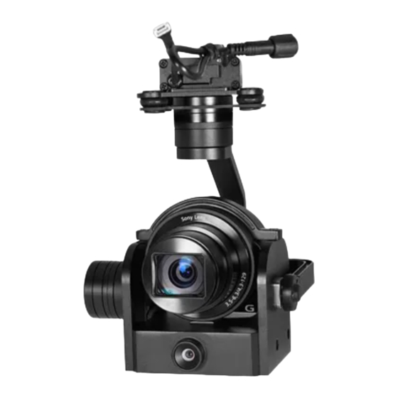
Important Note 1.Product Introduction 1.1 Introduction Z30UX is a high-precision 3-axis gimbal equipped with a 30x optical zoom SONY camera and 1080p prime lens sensor. It supports visible optical zoom, photographing and video. OSD can display the angle of pitch & yaw, zoom times, status of record and picture mode, also can select to turn off the OSD. -
Page 3: Standard Version
1.2 In the Box A. Standard Version Gimbal Camera USB to TTL Cable x 1 pc x 1 pc Copper Cylinder M3 Screw x 4 pcs x 8 pcs Power Cable x 1 pc B. Viewport Version Gimbal Camera USB to TTL Cable x 1 pc x 1 pc Copper Cylinder... -
Page 4: Installation Instruction
TTL / S.BUS Control Cable x 1 pc TTL Connect Cable x 3 pcs Ethernet Cable x 1 pc 2. Installation Instruction 2.1 Overview [11] [12] Control Box Back Side (Standard Version) [10] [11] [13] [12] Viewport (Viewport Version) - Page 5 [1] Control box [8] Roll axis motor [9] TF card slot [2] Upper damping board [10] Wide FOV prime lens [3] Lower damping board [11] 3-6S power interface [4] Damping ball [12] Ethernet interface [5] Yaw axis motor [13] Viewport unlock button [6] FHD zoom camera [7] Pitch axis motor Please ensure that there isn’t any obstacle while the...
- Page 6 2.2.2 Control Box Printing (Viewport Version) Front Side POWER Left Side ETHERNET UART & S.BUS Right Side...
- Page 7 2.3 Device Dimensions (Standard Version) Unit: mm 24.5 123.1...
- Page 8 2.3 Device Dimensions (Viewport Version) Unit: mm 41.6 Control Box 142.7 123.1...
- Page 9 2.4 Install Mounting Part (1) Find out the arrow on the gimbal which indicating the yaw heading of the payload (i.e. the lens direction when the camera power on), and synchronize with the direction specified by the UAV. (2) Fix one end of the copper cylinder on the screw hole of lower damping board, and use M3 screw to fasten it.
- Page 10 2.5 Viewport Release Instruction × 1. Make sure the two white stripes indicated in above picture are aligned with each other. (If the stripes are not aligned to each other, please pinch the connector part and turn it to left manually)
- Page 11 2. Align the white dot (unlock icon) to the red triangle (below unlock button), push the gimbal into the Viewport completely and then rotate the gimbal camera anticlockwise. 3. When you hear "click" sound (when red dot is aligned to the red triangle) means the gimbal camera and Viewport has been locked.
-
Page 12: Install Tf Card
2.6 Install TF Card TF (Micro SD card): Install the TF card to the card slot (Re. 2.1 Overview). Support max 128GB. Request Class 10 (10m/s) transmis- sion speed or higher and FAT32 or exFAT format. Make sure device is power off when inserting the TF card, hot plugging is not supported. -
Page 13: Signal Control
When using user interface software Viewlink for network connection, the network of external device (computer) should be the IP address: 192.168.2.2 (choose the last byte among 2~254, can not be 160 same as the gimbal), subnet mask: 255.255.255.0, Default gateway: 192.168.2.1, and all firewalls of the computer must be closed. - Page 14 PWM IN 5V OUTPUT Remote Controller Receiver Connection Diagram (Standard Version) Receiver Remote Controller Connection Diagram (Viewport Version)
- Page 15 PWM Control Operation Instruction 3.1.1 Pitch (PWM Pitch channel in to control Pitch. Joystick, rotary knob or 3-gear switch on remote control are optional. 3-gear switch as example.) Position 1 Position 2 Position 3 Low Gear Middle Gear High Gear Pitch Up Pitch Stop Pitch Down...
- Page 16 Position 1 Position 2 Position 3 Low Gear Middle Gear High Gear Position 1: Low speed mode, control pitch / yaw with this mode at lowest speed Position 2: Middle speed mode, control pitch / yaw with this mode at middle speed Position 3: High speed mode, control pitch / yaw with this mode at highest speed...
- Page 17 3.1.4 Zoom (PWM Zoom channel in to control Zoom. Joystick, rotary knob or 3-gear switch on remote control are optional. 3-gear switch as example.) Position 1 Position 2 Position 3 Low Gear Middle Gear High Gear Zoom Out Stop Zoom Zoom In 3.1.5 Focus ( not functional for this channel) Position 1...
- Page 18 Switch from Position 2 to 1: Take a picture, OSD display 'SNAP' a second in the top left corner. Switch from Position 2 to 3: Start record / repeat operation to stop record Start record, the OSD display rec hh:mm:ss for recording time Stop record, NO OSD display.
- Page 19 Gimbal Camera Cable RX (White) TX (Green) GND (Black) USB to TTL Cable Control Box Connection Diagram Standard Version USB to TTL Cable Viewport Control Box Connection Diagram Viewport Version...
-
Page 20: S.bus Control
TTL control protocol file. ViewLink is a user interface developed by Viewpro for Viewpro gimbal cameras, you can download it from Viewpro website (www.viewpro- tech.com) or ask distributors for installation package. - Page 21 5V OUTPUT Remote Control Receiver Wiring Diagram Standard Version Receiver Remote Control Wiring Diagram Viewport Version...
-
Page 22: Specification
S.Bus control mode: default S.Bus signal channel 9-15 to control gimbal camera functions (the function of channel is consistent with corresponding channel in PWM function description) Channel 9: Yaw Control Channel 10: Pitch Control Channel 11: Mode Control Channel 12: Zoom Control Channel 13: Focus Control Channel 14: Pic/Rec Control Channel 15: Multi Backup... - Page 23 Output voltage 5V (connect with PWM) Dynamic current 550mA @ 12V Idle current 480mA @ 12V Working environment '-0℃ ~ +40℃ temp Output IP(1920*1080) SD card (Up to 128G,class 10, FAT32 or ex Local-storage FAT format) Photo storage format JPG(5184*3888) Video storage format H264 (1920*1080) Control method...
- Page 24 Package meas. 360*300*250mm 5. FAQ 1. How to set the storage format of Z30UX? A: When the IP output resolution is set to 1280*720, the storage resolution is 1280*720; Storage resolution is 1920*1080 when the IP output resolution is set to 1920*1080; The video frame rate saved in the TF card is the same with the one set during IP output.
Need help?
Do you have a question about the Z30UX and is the answer not in the manual?
Questions and answers