Table of Contents

Related Manuals for Viewpro Z30TE


Summary of Contents for Viewpro Z30TE
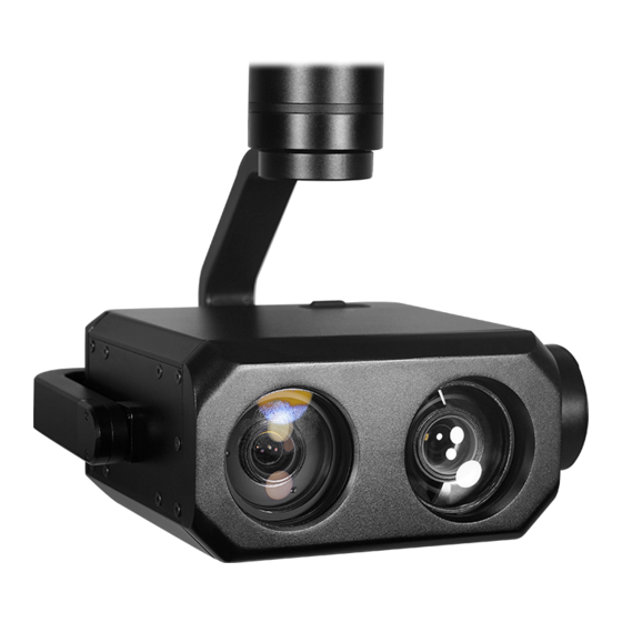
- Page 1 Z30TE 30x Zoom EO + Spotlight Illumination Night Vision Object Tracking Gimbal Camera User Manual User Manual Standard Version Viewport Version 标准版 快拆版 For more details please scan the QR code or visit our website: www.viewprotech.com...
-
Page 2: Disclaimer And Warning
When the external GPS and time input, the OSD can display angle, zoom times, photographing and video status and tracking frame, also can select to turn off the OSD. Z30TE has geotagging function. GPS coordinate and shooting time can be saved in image file, OSD can display GPS and real-time as well. -
Page 3: Standard Version
1.2 In the Box A. Standard Version Gimbal Camera USB to TTL Cable x 1 pc x 1 pc Copper Cylinder M3 Screw x 4 pcs x 8 pcs Power Cable x 1 pc B. Viewport Version Gimbal Camera USB to TTL Cable x 1 pc x 1 pc Copper Cylinder... -
Page 4: Installation Instruction
TTL / S.BUS Control Cable x 1 pc TTL Connect Cable x 3 pcs Ethernet Cable x 1 pc 2. Installation Instruction 2.1 Overview [11] [13] [12] Control Box Back Side [10] (Standard Version) [11] [14] [13] Viewport [12] (Viewport Version) - Page 5 [8] TF card slot [1] Control box [2] Upper damping board [9] Roll axis motor [3] Lower damping board [10] Pitch axis motor [4] LED illumination camera [11] 3-6S power interface [5] FHD zoom camera [12] Micro HDMI interface [6] Damping ball [13] Ethernet interface [7] Yaw axis motor [14] Viewport unlock button...
- Page 6 2.2.2 Control Box Printing (Viewport Version) Front Side POWER Left Side ETHERNET UART & S.BUS Right Side...
- Page 7 2.3 Device Dimensions (Standard Version) Unit: mm 62.2 150.2 153.9...
- Page 8 2.3 Device Dimensions (Viewport Version) Unit: mm 41.6 Control Box 150.2 153.9...
- Page 9 2.4 Install Mounting Part (1) Find out the arrow on the gimbal which indicating the yaw heading of the payload (i.e. the lens direction when the camera power on), and synchronize with the direction specified by the UAV. (2) Fix one end of the copper cylinder on the screw hole of lower damping board, and use M3 screw to fasten it.
- Page 10 2.5 Viewport Release Instruction × 1. Make sure the two white stripes indicated in above picture are aligned with each other. (If the stripes are not aligned to each other, please pinch the connector part and turn it to left manually)
- Page 11 2. Align the white dot (unlock icon) to the red triangle (below unlock button), push the gimbal into the Viewport completely and then rotate the gimbal camera anticlockwise. 3. When you hear "click" sound (when red dot is aligned to the red triangle) means the gimbal camera and Viewport has been locked.
- Page 12 2.6 Install TF Card TF (Micro SD card): Install the TF card to the card slot (Re. 2.1 Overview). Support max 128GB. Request Class 10 (10m/s) transmis- sion speed or higher and FAT32 or exFAT format. Make sure device is power off when inserting the TF card, hot plugging is not supported.
-
Page 13: Signal Control
Above output mode is optional, HDMI and SDI output cannot coexist at the same time. Please subject to your actual product. When using user interface software Viewlink for network connection, the network of external device (computer) should be the IP address: 192.168.2.2 (choose the last byte among 2~254, can not be 119 same as the gimbal), subnet mask: 255.255.255.0, Default gateway: 192.168.2.1, and all firewalls of the... - Page 14 PWM IN 5V OUTPUT Remote Controller Receiver Connection Diagram (Standard Version) Receiver Remote Controller Connection Diagram (Viewport Version)
- Page 15 3.1.2 PWM Control Operation Instruction 1) Pitch (PWM Pitch channel in to control Pitch. Joystick, rotary knob or 3-gear switch on remote control are optional. 3-gear switch as example.) Position 1 Position 2 Position 3 Low Gear Middle Gear High Gear Pitch Up Pitch Stop Pitch Down...
- Page 16 Position 1 Position 2 Position 3 Low Gear Middle Gear High Gear Position 1: Low speed mode, control pitch / yaw with this mode at lowest speed Position 2: Middle speed mode, control pitch / yaw with this mode at middle speed Position 3: High speed mode, control pitch / yaw with this mode at highest speed...
- Page 17 5) Zoom (PWM Zoom channel in to control Zoom. Joystick, rotary knob or 3-gear switch on remote control are optional. 3-gear switch as example.) Position 1 Position 2 Position 3 Low Gear Middle Gear High Gear Zoom Out Stop Zoom Zoom In Note: In the laser night vision mode, the laser aperture can be zoom in/out with the picture synchronously when control zoom in/out.
- Page 18 Position 1 Position 2 Position 3 Low Gear Middle Gear High Gear Switch from Position 2 to 1: Take a picture OSD display 'REC IMG' a second. Switch from Position 2 to 3: Start record / repeat operation to stop record Start record, the OSD display rec hh:mm:ss.
- Page 19 3.2 Serial Port / TTL Control TTL communication requirements: TTL signal is 3.3V, baud rate: 115200, data bit 8, stop bit 1, no parity, HEX send and receive. Connection Diagram (PC - USB to TTL Cable- Gimbal Camera as example): Gimbal Camera Cable RX (White)
-
Page 20: S.bus Control
TTL control protocol file. ViewLink is a user interface developed by Viewpro for Viewpro gimbal cameras, you can download it from Viewpro website (www.viewpro- tech.com) or ask distributors for installation package. - Page 21 5V OUTPUT Remote Control Receiver Wiring Diagram Standard Version Receiver Remote Control Wiring Diagram Viewport Version...
- Page 22 (please contact with our technical support for the setting instruction.) 3.4 TCP control For Viewpro gimbal cameras with Ethernet output, the default IP address is: 192.168.2.119, control port: 2000. You can send the corresponding protocol to realize TCP control after connecting.
-
Page 23: Specification
4. Specification Hardware Parameter Working voltage Input voltage 3S ~ 6S Output voltage 5V (connect with PWM) Dynamic current 1700mA @ 12V Idle current 770mA @ 12V Working environment -20℃ ~ +60℃ temp micro HDMI (HD output 1080P 25/30/50/60 Output fps) / IP (720P/1080P 25/30fps) / DJI Skyport SD card (Up to 128G,class 10, FAT32 or ex Local-storage... - Page 24 Pitch/Tilt: -45°~90°,Yaw/Pan: ±290° / Controllable Range ±360°*N (IP output version) Vibration angle Pitch/Roll: ±0.02°, Yaw:±0.02° One-key to center √ Camera spec Imager Sensor SONY 1/2.8" "Exmor R" CMOS Picture quality Full HD 1080 (1920*1080) Effective pixel 2.13MP Lens optical zoom 30x, F=4.3~129mm Digital zoom 12x (360x with optical zoom)
- Page 25 Auto, ATW, Indoor, Outdoor, One Push WB, White balance Manual WB, Outdoor Auto, Sodium Vapor Lamp (Fix/Auto/Outdoor Auto) Shutter speed 1/1s to 1/10,000s, 22 steps Backlight compensation Aperture control 16 steps Defog Camera Object Tracking Update rate of 50Hz deviation pixel Output delay of deviation pixel Minimum object...
- Page 26 LED Light Supplement Effective range ≤300 meters Light color White 6500K R90 power zoom synchronously, 70°~6.0° Illumination angle adjustable Zoom time ≤3s (wide end - tele end) LED electric power consumption Lumen value >1000Lm Tele end 2.0°: effective range 500 meters, Illumination angle spot diameter ≤18 meters Wide end 70°: effective range ≥...
- Page 27 25fps or 30fps for optional. 4. What special environment can Z30TE be used in? A: The observation range of Z30TE is up to 300 meters at dark night environment. And the image is in black and white mode.
Need help?
Do you have a question about the Z30TE and is the answer not in the manual?
Questions and answers