
Related Manuals for Viewpro Z-Fusion pro


Summary of Contents for Viewpro Z-Fusion pro
- Page 1 EO + IR Dual Sensor Fusion Gimbal Camera User Manual User Manual Standard Version Viewport Version 标准版 快拆版 For more details please scan the QR code or visit our website: www.viewprotech.com...
-
Page 2: Disclaimer And Warning
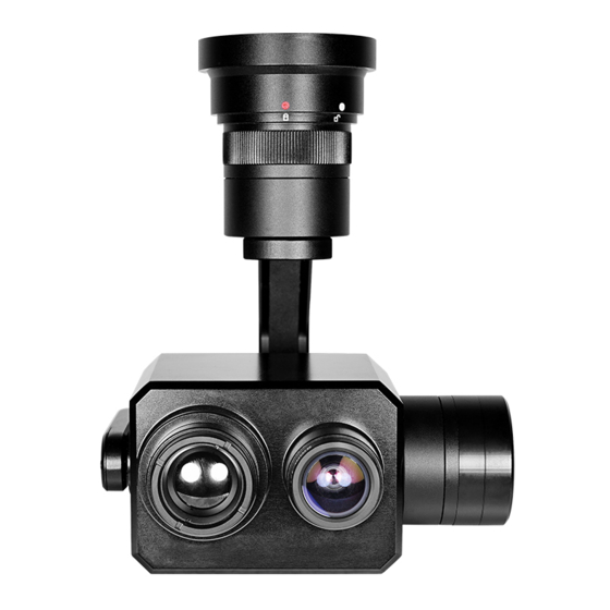
Important Note 1.Product Introduction 1.1 Introduction Z-Fusion pro is a high-precision 3-axis gimbal integrated with a EO prime lens camera and a 19mm lens 640*480 IR thermal sensor with dual fusion technology. Combined with the advantages of infrared heat source detection and visible detail observation, it can quickly and accurately locate hot spots, hidden spots, etc. -
Page 3: Standard Version
1.2 In the Box A. Standard Version Gimbal Camera USB to TTL Cable x 1 pc x 1 pc Copper Cylinder M3 Screw x 4 pcs x 8 pcs Power Cable x 1 pc B. Viewport Version Gimbal Camera USB to TTL Cable x 1 pc x 1 pc Copper Cylinder... -
Page 4: Installation Instruction
TTL / S.BUS Control Cable x 1 pc TTL Connect Cable x 3 pcs Ethernet Cable x 1 pc 2. Installation Instruction 2.1 Overview [11] [13] [12] Control Box Back Side [10] (Standard Version) [11] [14] [13] Viewport [12] (Viewport Version) - Page 5 [8] TF card slot [1] Control box [2] Upper damping board [9] Roll axis motor [3] Lower damping board [10] Pitch axis motor [4] EO prime lens camera [11] 3-6S power interface [5] Infrared thermal camera [12] Micro HDMI interface [6] Damping ball [13] Ethernet interface [7] Yaw axis motor...
- Page 6 2.2.2 Control Box Printing (Viewport Version) Front Side POWER Left Side ETHERNET UART & S.BUS Right Side...
- Page 7 2.3 Device Dimensions (Standard Version) Unit: mm 69.9 60.0 69.8 69.9 107.1 121.1...
- Page 8 2.3 Device Dimensions (Viewport Version) Unit: mm 78.0 Control Box 91.0 91.0 91.0 81.5 81.5 107.1 121.1...
- Page 9 2.4 Install Mounting Part (1) Find out the arrow on the gimbal which indicating the yaw heading of the payload (i.e. the lens direction when the camera power on), and synchronize with the direction specified by the UAV. (2) Fix one end of the copper cylinder on the screw hole of lower damping board, and use M3 screw to fasten it.
- Page 10 2.5 Viewport Release Instruction × 1. Make sure the two white stripes indicated in above picture are aligned with each other. (If the stripes are not aligned to each other, please pinch the connector part and turn it to left manually)
- Page 11 2. Align the white dot (unlock icon) to the red triangle (below unlock button), push the gimbal into the Viewport completely and then rotate the gimbal camera anticlockwise. 3. When you hear "click" sound (when red dot is aligned to the red triangle) means the gimbal camera and Viewport has been locked.
- Page 12 2.6 Install TF Card TF (Micro SD card): Install the TF card to the card slot (Re. 2.1 Overview). Support max 128GB. Request Class 10 (10m/s) transmis- sion speed or higher and FAT32 or exFAT format. Make sure device is power off when inserting the TF card, hot plugging is not supported.
-
Page 13: Signal Control
Above output mode is optional, HDMI and AV output cannot coexist at the same time. Please subject to your actual product. When using user interface software Viewlink for network connection, the network of external device (computer) should be the IP address: 192.168.1.2 (choose the last byte among 2~254, can not be 100 same as the gimbal), subnet mask: 255.255.255.0, Default gateway: 192.168.1.1, and all firewalls of the... - Page 14 PWM IN 5V OUTPUT Receiver Remote Controller Connection Diagram (Standard Version) Receiver Remote Controller Connection Diagram (Viewport Version)
- Page 15 3.1.2 PWM Control Operation Instruction 1) Pitch (PWM Pitch channel in to control Pitch. Joystick, rotary knob or 3-gear switch on remote control are optional. 3-gear switch as example.) Position 1 Position 2 Position 3 Low Gear Middle Gear High Gear Pitch Up Pitch Stop Pitch Down...
- Page 16 Position 1 Position 2 Position 3 Low Gear Middle Gear High Gear Position 1: Low speed mode, control pitch / yaw with this mode at lowest speed Position 2: Middle speed mode, control pitch / yaw with this mode at middle speed Position 3: High speed mode, control pitch / yaw with this mode at highest speed...
- Page 17 4) Zoom (PWM Zoom channel in to control Zoom. Joystick, rotary knob or 3-gear switch on remote control are optional. 3-gear switch as example.) Position 1 Position 2 Position 3 Low Gear Middle Gear High Gear Zoom Out Stop Zoom Zoom In Switch from Position 2 to 1: Picture in Picture, repeat operation for switching: PIP/PIP-A/PIP-B/VL/IR/FUSION-A/FUSION-B...
- Page 18 Position 1 Position 2 Position 3 Low Gear Middle Gear High Gear Switch from Position 2 to 1: Take a picture OSD display 'REC IMG' a second. Switch from Position 2 to 3: Start record / repeat operation to stop record Start record, the OSD display rec hh:mm:ss.
- Page 19 Gimbal Camera Cable RX (White) TX (Green) GND (Black) USB to TTL Cable Control Box Connection Diagram Standard Version USB to TTL Cable Viewport Control Box Connection Diagram Viewport Version...
-
Page 20: S.bus Control
TTL control protocol file. ViewLink is a user interface developed by Viewpro for Viewpro gimbal cameras, you can download it from Viewpro website (www.viewpro- tech.com) or ask distributors for installation package. - Page 21 5V OUTPUT Remote Control Receiver Wiring Diagram Standard Version Receiver Remote Control Wiring Diagram Viewport Version...
- Page 22 S.Bus control mode: default S.Bus signal channel 9-15 to control gimbal camera functions (the function of channel is consistent with corresponding channel in PWM function description) Channel 9: Yaw Control Channel 10: Pitch Control Channel 11: Mode Control Channel 12: Zoom Control Channel 13: Focus Control Channel 14: Pic/Rec Control Channel 15: Multi Backup...
-
Page 23: Specification
4. Specification Hardware Parameter Working voltage Input voltage 3S ~ 6S Output voltage 5V (connect with PWM) Dynamic current 550~700mA @ 12V Idle current 550mA @ 12V Working environment -20℃ ~ +60℃ temp micro HDMI(FHD output 1080P 30fps) / Output IP(1080P/720p 25/30fps) Support (PIP, PIP-A, PIP-B, Fusion-A, PIP model... - Page 24 Pitch/Tilt: -45°~90°, Yaw/Pan: ±290° / ±360° Controllable Range *N (IP output version) Vibration angle Pitch/Roll: ±0.02°, Yaw:±0.02° One-key to center √ Camera spec Imager Sensor SONY sensor 1/1.8" "Exmor R" CMOS Effective pixel Min illumination 0.05lux Lens viewing angle 50.0° x 38.0° Thermal imager spec Lens size 19mm...
- Page 25 Detective Distance 1714 meters (Car: 4.2x1.8m) Recognize Distance 428 meters (Car: 4.2x1.8m) Verified Distance 214 meters (Car: 4.2x1.8m) Uncooled long wave (8μm~14μm) thermal Working mode imager Detector pixel 640*480 Pixel size 17μm Focusing method prime lens NETD ≤50mK (@30℃) Outline-drawning, white hot, black red, green Color palette blue yellow red,ect.
- Page 26 TF card is the same with the one set during IP output. The frame rate is 25fps or 30fps for optional. 2. How to modify the network parameter of Z-Fusion Pro? A: Login in default IP address with IE browser, user: "admin", password: “admin”, and Enter setting interface, select the last option...
Need help?
Do you have a question about the Z-Fusion pro and is the answer not in the manual?
Questions and answers