
Subscribe to Our Youtube Channel
Related Manuals for Advantech FMS-3154R


Summary of Contents for Advantech FMS-3154R
- Page 1 Administrator’s Guide and Operating Instructions Administrator’s Guide and Operating Instructions Web-enabled Digital Video Server FMS-3154R...
- Page 2 Administrator’s Guide and Operating Instructions WARNING TO REDUCE RISK OF FIRE OR ELECTRIC SHOCK, DO NOT EXPOSE THIS APPLIANCE TO RAIN OR MOISTURE. CAUTION DO NOT REMOVE COVER. NO USER SERVICEABLE PARTS INSIDE. REFER SERVICING TO QUALIFIED SERVICE PERSONNEL. WARNING: This equipment has been tested and found to comply with the limits for a Class “A”...
- Page 3 Administrator’s Guide and Operating Instructions PRECAUTIONS Refer all work related to the installation of this product to qualified service personnel or system installers. Do not block the ventilation opening or slots on the cover. Do not drop metallic parts through slots. This could permanently damage the appliance.
-
Page 4: Table Of Contents
Administrator’s Guide and Operating Instructions Table of Contents 1. Product Overview………………….……………………….……... 1.1 Features…………………..……….…………..…………………... 1.2 Technical Overview…….….…….………………………….…….. 2. Front & Rear Panels….…….……………………………….……. 3. System Installation…….…….……………………………….…… 3.1 Before Installation…….……….…………………………….……. 3.2 Basic Connections…………….…………………………….…….. 3.3 Optional Connections…………..…………………………….…… 4. Main Screen…………………………………………..……….…... 5. Basic Operations & Log Display……………………..………..…. 5.1 Version Display……………………………..…………….…….…... -
Page 5: Product Overview
Administrator’s Guide and Operating Instructions 1. Product Overview The FMS-3154R, 4-Port Digital Video Server, combines the power of triplex multiplexing and digital video recording into one comprehensive unit. The compact design is suitable for conventional surveillance in limited spaces where only 4 cameras are required. -
Page 6: Technical Overview
Administrator’s Guide and Operating Instructions 1.2 Technical Overview 1.2.1 Video Input and Output The digital video recorder is designed to support either NTSC/EIA or PAL/CCIR standard. To make the auto detection of video standard work, at least one camera must be connected to the video input. Camera input impedance termination is set independently for each camera automatically. - Page 7 Administrator’s Guide and Operating Instructions event log, etc. Motion detection options for different time types can be set for each camera input using a 16 (width) by 12 (height) target overlay. You can also enable or disable motion alarms for different time types.
-
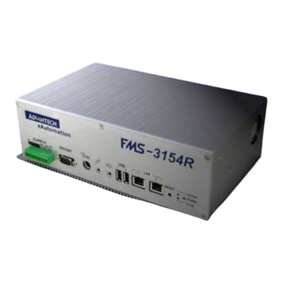
Page 8: Front & Rear Panels
Administrator’s Guide and Operating Instructions 2. Front & Rear Panels The following is a brief overview of the rear panel and front panel of FMS-3154R. Rear Panel 1. Power Socket: Connects to the DC 24V power source or the AC adapter (system accepts 18V~30V DC power source). - Page 9 Administrator’s Guide and Operating Instructions Front Panel 9. Alarm In 1-4: Connects to alarm inputs 1-4 & 1 common ground. 10. Alarm Out: Connects to 2 Normally Closed alarm outputs (1-2), 2 Normally Open alarm outputs (3-4) & 1 common ground. 11.
- Page 10 Administrator’s Guide and Operating Instructions Side Panel 20. Hard Disk Tray: Please make sure to set the hard disk as master. To access the hard disk, use the attached key to open the cover and remove the hard disk holder. The key can’t be removed from the cover while the cover is open.
-
Page 11: System Installation
Administrator’s Guide and Operating Instructions 3. System Installation The installations described below should be made by qualified service personnel or system installers. 3.1 Before Installation Please refer to the following diagram for the system connections. -
Page 12: Basic Connections
Administrator’s Guide and Operating Instructions 3.2 Basic Connections Cameras Connect each of the camera video input connector to the video output from a camera or other composite video source. Connect 1-4 color cameras or 1-4 B/W cameras to the system, the color camera and B/W camera can not be mixed connected to the system. - Page 13 LAN connector to a standard RJ45 connector Ethernet cable. Shown in below is an example of connection. Modem FMS-3154R is enabled control from the PC via modem. Connect the RS 232 connector to a modem. Shown in below is an example of connection.
-
Page 14: Main Screen
Administrator’s Guide and Operating Instructions 4. Main Screen Camera 1 Live Camera 2 Live Camera 3 Live Camera 4 Live The diagram above is the main screen display. The icons on the lower corner of the screen are mainly for control and configuration, those on the right corner for status indication. - Page 15 Administrator’s Guide and Operating Instructions Config – To configure (setup) the behaviors of the system. Login – To login the system as Administrator, Supervisor or Operator. Sequence Mode / Static Page Mode – To toggle between Sequence Mode and Static Page Mode. In Sequence Mode, each page in the designated sequence will be shown for its preset dwelling time sequentially.
- Page 16 Administrator’s Guide and Operating Instructions There are 4 kinds of devices in the status indication. The displaying order is Camera, Alarm Output, Hard Disk, Alarm Input, then back to Camera. Each status bar stands for the status of one device, the bottommost for ID#1. There are 5 different colors: GRAY/BLACK –...
-
Page 17: Basic Operations & Log Display
Administrator’s Guide and Operating Instructions 5. Basic Operations & Log Display If the user does not login the system, he will be treated as a guest and can only view the live video display and device status. To login as an Operator or Supervisor, please click on the Login icon, and enter the appropriate Operator’s Login name and Password (For Operator, the factory default value for both of them is operator, for Supervisor,... -
Page 18: Version Display
Administrator’s Guide and Operating Instructions There are 5 kinds of event logs: Alarm, Motion, Video Loss, Hard Disk Full, and Power On/Off. To view the event Log display, please click on the Log icon. The screen will be shown as below: If you logged in as Administrator, the Delete button and Delete All button will be enabled. -
Page 19: Setup (Administrator)
Administrator’s Guide and Operating Instructions 6. Setup (Administrator) To login as an Administrator, please click on the Login icon, and enter the appropriate Administrator’s Login name and Password (the factory default value for both of them is admin). To setup the behaviors of the system, please click on the Config icon. The configuration menu will pop up as below. -
Page 20: Time Type Setup
Administrator’s Guide and Operating Instructions 6.1 Time Type Setup The behavior for the system is the same when it’s in the same Time Type (or Time Mode). Please refer to Camera Setup and Motion Setup for how they depend on Time Type. There are 2 default Time Types, On duty and Off duty, in the system. -
Page 21: Day Type Setup
Administrator’s Guide and Operating Instructions 6.2 Day Type Setup The daily behaviors for the system are the same for those days configured as of the same Day Type. There are 2 default Day Types, WORK DAY (Monday through Friday) and HOLIDAY (Saturday and Sunday), in the system. -
Page 22: Calendar Setup
Administrator’s Guide and Operating Instructions 6.3 Calendar Setup The Calendar setup is provided for the administrator to set the Day Type of each calendar day. It’s designed to be a Perpetual Calendar. However, up to 10 years of calendar days can be configured at any specific time. -
Page 23: Alarm Action Setup
Administrator’s Guide and Operating Instructions 6.4 Alarm Action Setup The Alarm Actions allow the administrator to define how the digital video recorder responds to the triggered alarm from the Alarm Inputs. There are up to 4 Alarm Actions that correspond to 4 (Focus) Cameras for most applications. - Page 24 Administrator’s Guide and Operating Instructions Focus Camera – To define the camera that will respond to this Alarm Action. The default settings are Camera 1 for Alarm Action 1, Camera 2 for Alarm Action 2, and so on. Pre-record – Pre-record time to define how long (in seconds) before the Alarm Action is triggered the Focus Camera shall be intensively recorded (Note 2).
- Page 25 Administrator’s Guide and Operating Instructions Log – Log to event log list or not. Please refer to Log Display for the details. Show Message – To display the alarm message or not when the Alarm Action is triggered. Any Key To Stop – When the Alarm Action is triggered, the internal buzzer and Alarm Out relay may be activated.
-
Page 26: Motion Action Setup
Administrator’s Guide and Operating Instructions 6.5 Motion Action Setup The Motion Actions allow the administrator to define how the digital video recorder responds to the detected motion for the cameras. There are up to 4 Motion Actions that correspond to 4 Alarm Outputs for most applications. -
Page 27: Video Loss Action Setup
Administrator’s Guide and Operating Instructions 6.6 Video Loss Action Setup The Video Loss Actions allow the administrator to define how the digital video recorder responds to the detected video loss for the cameras. There are up to 4 Video Loss Actions that correspond to 4 Alarm Outputs for most applications. -
Page 28: Hard Disks Full Action Setup
Administrator’s Guide and Operating Instructions 6.7 Hard Disk Full Action Setup The Hard Disk Full Actions allow the administrator to define how the digital video recorder responds when the hard disk drive reaches the maximum storage capacity. Operations: After the HDD Full Action menu item is selected, the HDD Full Action Setup dialog box will be shown on the screen. - Page 29 Administrator’s Guide and Operating Instructions Alarm Out – To define which Alarm Output will be triggered when the hard disk capacity is full. NC and NO signals are available, please refer to Alarm Out Setup. Click on the Down arrow button to select one of the Alarm Outputs (AO 1-4).
-
Page 30: Camera Setup
Administrator’s Guide and Operating Instructions 6.8 Camera Setup The Camera Setup allows the administrator to define the behaviors for each Camera at each Time Type. There are up to 4 Cameras connected to the system. For each Camera and each Time Type, you may configure the behaviors as shown on the screen and described below. - Page 31 Administrator’s Guide and Operating Instructions Installed – Check this item if the selected Camera is installed. If the selected Camera is installed, all the items in the Behaviors For Each Camera are settable. The default setting is installed. Recording Quality For All Cameras – The range is 0-10, with 0 the lowest (rough) quality, 10 the highest (fine) quality.
- Page 32 Administrator’s Guide and Operating Instructions Note 1 : The maximum recording rate for the system is 25 FPS for PAL, 30 FPS for NTSC. If the total recording rate for all cameras is greater than 25/30 FPS, the system will decrease the recording rate for each camera averagely to make the total 25/30 FPS.
-
Page 33: Alarm In Setup
Administrator’s Guide and Operating Instructions 6.9 Alarm In Setup The Alarm In Setup allows the administrator to define the behaviors for each Alarm Input at each Time Type. There are 4 Alarm Inputs connected to the system. For each Alarm Input and each Time Type, you may enable/disable and select its corresponding Alarm Action. - Page 34 Administrator’s Guide and Operating Instructions to the Alarm Input Terminal on the rear panel of the system. Use the Down arrow button to select the signal type. Enable Alarm Action – Check to Enable Alarm Action for the selected Alarm Input at the selected Time Type. Alarm Action –...
-
Page 35: Alarm Out Setup
Administrator’s Guide and Operating Instructions The Alarm Out Setup allows the administrator to define the tag name for each Alarm Output. There are up to 2 Normally Closed (NC) signals (AO 1-2) and 2 Normally Open (NO) signals (AO 3-4) for the system. -
Page 36: Display Sequence Setup
Administrator’s Guide and Operating Instructions 6.11 Display Sequence Setup The Display Sequence Setup allows the administrator to define the Sequence Mode display. Please refer to Chapter 4 for Sequence Mode display. For the definition of the Display Pages in each Display Sequence, please refer to Display Page Setup. -
Page 37: Display
Administrator’s Guide and Operating Instructions 6.12 Display Page Setup The Display Page Setup allows the administrator to define the Display Pages in Sequence Mode display and Static Page Mode display (please refer to Chapter 4). Operations: After the Display Pages menu item is selected, the Display Page Setup dialog box will be shown on the screen. - Page 38 Administrator’s Guide and Operating Instructions Static Page Mode – To set the Display Pages for Static Page Mode display. Sequence No – To select the Sequence Number in Sequence Mode display. Use the Down arrow button to select the number. Page No - To select the Page Number for the selected Sequence Number in Sequence Mode display.
-
Page 39: Motion Setup
Administrator’s Guide and Operating Instructions 6.13 Motion Setup The Motion Setup allows the administrator to configure how motion detection works for each Camera at each Time Type. For each Camera and each Time Type, you may configure the Detection Area (16x12 grids) and Sensitivity as shown on the screen and described below. - Page 40 Administrator’s Guide and Operating Instructions Camera – Use the Down arrow button to select the camera. Time Type - Use the Down arrow button to select the Time Type. Set – To set the Detection Area – active at down position. Clear –...
-
Page 41: Password Setup
Administrator’s Guide and Operating Instructions 6.14 Password Setup The Password Setup allows the administrator to set the new Login names and Passwords for the Administrator, Supervisor and Operator. The default (Login, Password) for the Administrator is (admin, admin), the Supervisor (Supervisor, Supervisor), the Operator (operator, operator). -
Page 42: System Configurations
Administrator’s Guide and Operating Instructions 6.15 System Configurations The System Configurations Setup allows the administrator to set up the communication, printer model, E-Mail notification, daylight saving time, TV system and software upgrade. Operations: After the System menu item is selected, the System Configurations dialog box will be shown on the screen. - Page 43 Administrator’s Guide and Operating Instructions Gateway IP address – Enter the corresponding IP address while the gateway is enabled. Domain Name Server IP Address – Enter the correct Domain Name Server for mapping Domain Names to IP addresses. The default setting is 168.095.001.001. The user can also defines their local Domain Name Sever for name-to address translation, however, please make sure to define a correct Domain Name Server IP Address.
- Page 44 Mail item is selected. msa.hinet.net adm@advantech.com.tw SMTP server – Enter the address and port number for the SMTP Server. The address can be either domain name or IP address, and the port number for SMTP server is normally 25.
- Page 45 Administrator’s Guide and Operating Instructions North America – Clocks are turned forward an hour begins at 2 a.m. on the first Sunday in April, time reverts to standard time at 2 a.m. on the last Sunday in October. European Union – Clocks are turned forward an hour begins at 1 a.m.
-
Page 46: Day/Time Setup (Administrator)
Administrator’s Guide and Operating Instructions 7. Date/Time Setup (Administrator) If you are an Administrator, please click on the Time displaying on the Main Screen to enter the Date/Time Setup for the system. The date is in YYYY/MM/DD format, whilst the time in military hour format (HH:MM:SS). -
Page 47: Image Playback And Archive (Administrator, Supervisor)
Administrator’s Guide and Operating Instructions 8. Image Playback and Archive (Administrator, Supervisor) On the Main Screen, please click on the Playback Panel icon, the screen will be shown as below: Camera 2 Play Camera 1 Play Camera 4 Play Camera 3 Play The icons on the lower corner of the screen are changed to the icons for video playback and archive, those on the right corner not changed (for status indication). - Page 48 Administrator’s Guide and Operating Instructions Select HDD & Range – To select the playback Hard Disk and the playback range in that Hard Disk. Click on it, and the Select HDD & Range dialog box will be shown on the screen as described in the next paragraph.
- Page 49 Administrator’s Guide and Operating Instructions Replay – To repeat playing the selected video over and over again when the button is at DOWN position. Speed – The playing speed, ranging from 1/6 (slowest) through 5 (fastest). For speed 1/6 – 2, each image for the selected playback cameras will be displayed in its respective video window.
-
Page 50: Select Hdd & Range Dialog Box
Administrator’s Guide and Operating Instructions 8.1 Select HDD & Range Dialog Box When the user click on the Select HDD & Range icon on the Playback Panel, the Select HDD & Range dialog box will be shown on the screen. The system provides user to search the image either by HDD location or by time. - Page 51 Administrator’s Guide and Operating Instructions Start/End Section No – 32 MB/Section or 32 Slices/Section for the system. Use the Down arrow button to select the Start/End Section Start/End Slice No – 1 MB/Slice for the system. Use the Down arrow button to select the Start/End Slice No. Start/End Date/Time –...
- Page 52 Administrator’s Guide and Operating Instructions To search by time, the diagram will be shown as below. 01-01-01 Search by Time 2001/3/05 Mon, 10:10:50 N Y N N N Y Y N N N Y Y N N N N N Y N N N Y Y N N N Y Y N N N N N Y N N N Y Y N N N Y Y N N N N N Y N N N Y Y N Use the Down arrow to select the desired start date and time, click on the...
-
Page 53: Remote Control
FMS-3154R from any PC in anywhere. The remote computer does not need to have the FMS-3154R software or any special hardware and software installed. Connecting the Remote PC and Server Before you start, please verify the connection between FMS-3154R and the modem or network. - Page 54 Administrator’s Guide and Operating Instructions The video image can be displayed in full or quad screen mode, and the time shown on each window refers to the time on FMS-3154R system clock. The following is the brief description of each item above.
- Page 55 Note. 2 The Login Name and Password are the same as used in FMS-3154R, the Administrator can operate all the functions on remote end, the Supervisor can view the live video and playback image, and the Operator can only view the live video.
-
Page 56: Appendix A - Specifications
Administrator’s Guide and Operating Instructions Appendix A – Specifications Video Format NTSC/EIA or PAL/CCIR, auto-sensing & manual switch Video Input 4 camera inputs (BNC), 1Vp-p/75ohm Video Output 1 VGA monitor output, D-Sub 15 pin JPEG and MPEG-1 I Frame Video Compression Video Resolution 352x240 (NTSC) or 352x288 (PAL) Video Display... -
Page 57: Appendix B - Time Lapse Mode Recording Time
Administrator’s Guide and Operating Instructions Appendix B – Time Lapse Mode Recording Time FMS-3154R Time Lapse Mode Recording Time (system storage: 60GB) (Estimated with typical image – low noise level) NTSC / JPEG Fine(10) Normal(5) Rough(0) Total Capture Rate hour... - Page 58 Administrator’s Guide and Operating Instructions PAL / JPEG Fine(10) Normal(5) Rough(0) Total Capture Rate hour min hour hour (FPS) 12.5 0.83 0.25 0.17 1277 PAL / MPEG-1 Fine(10) Normal(5) Rough(0) Total Capture Rate hour hour hour (FPS) 12.5 0.83 0.25 0.17 1011 1517...
-
Page 59: Appendix C - Simulated Keyboard
Administrator’s Guide and Operating Instructions Appendix C – Simulated Keyboard There are situations that the user will be asked to enter a numeric or alphanumeric string. So, a Simulated Keyboard is designed for the user to use the mouse for all the operations. Please refer to the following diagram for the details. - Page 60 Administrator’s Guide and Operating Instructions Q: How to setup event recording? A: Please setup the Alarm Recording rates for the Cameras at different Time Types, the different Actions, and the enable/disable items for the Cameras and the Alarm Inputs. The alarm recording rates are also event-recording rates. Q: How to black out the live images for the cameras? A: To black out the live images for the cameras, login as Administrator and set those cameras as playback in the Sequence Mode display &...
- Page 61 P/N: MDR4G00200 Jan.16.2002...
Need help?
Do you have a question about the FMS-3154R and is the answer not in the manual?
Questions and answers