Table of Contents
Advertisement
Quick Links
Advertisement
Table of Contents

Related Manuals for Advantech SKY-8101D


Summary of Contents for Advantech SKY-8101D
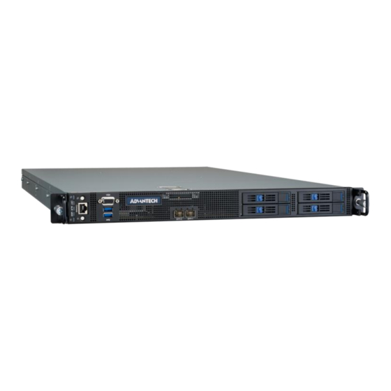
- Page 1 SKY-8101D Compact 1U High Performance Server...
-
Page 2: Table Of Contents
1. General ..............................3 1.1 System Overview ........................3 1.2 Product Version ......................... 4 1.3 Technical Specifications ......................4 1.3.1 SKY-8101D System Specification ..................4 1.3.2 System Dimensions ......................6 1.4 Detail Description ........................7 1.4.1 Front Elements ........................ 7 1.4.2 Rear Panel ........................ -
Page 3: General
1. General 1.1 System Overview The Advantech SKY-8101D is a highly configurable high performance server designed to balance the best in x86 server-class processing with maximum I/O and offload density in a 1U 29.5" depth chassis. The system is a cost effective, robust platform optimized for superior reliability in business critical applications such as communications, edge and industrial high performance computing. -
Page 4: Product Version
1.2 Product Version The SKY-8101D is available in the following standard configurations. Contact your Advantech representative for availability of other configuration options. Table 1-1: Available Product Versions Model Name Configurations 29.5” 1U server w GSMB-8101D, dual 4 bay 2.5" Skylake-SP socket, redundant AC 1200W... - Page 5 Resilient to single fan failure - Aspeed AST2500 BMC - Advanced Lights Out Management compliant to IPMI2.0 with security and System availability enhancements Advantech BMC Management - iKVM Support - Configurable shared or dedicated NIC support Dimension 438.00 x 749.7 x 44.20 mm (17.24" x 29.50" x 1.74")
-
Page 6: System Dimensions
1.3.2 System Dimensions The system dimensions (in mm) are shown below: Unit:mm [inch] Figure 2-2: System Dimension... -
Page 7: Detail Description
PCIe x8, so the platform can only support up to 2x NVMe SSD + 2x SATA/SAS HDD/SSD. 1.4.1.1 Disk Bay Details The SKY-8101D supports four hot swappable 2.5” HDD/SSD/NVMe at the front. Figure 4-4: Disk Bays Table 1-3: Disk Bay... - Page 8 ADT2A Activity LED (amber) Status LED ADT3A Button Pushing the button will allow the tray handle to open if unlocked ADT4A Handle Tray handle ADT5A 1.4.1.2 LEDs Details The SKY-8101D supports an array of status LEDs and buttons at location...
- Page 9 failure) Major Alarm (System Status LED) One system status LED in red color is provided for the SKY-8101D system chassis. The system status LED behavior is based on Platform Event Filtering (PEF) alert AB3A MJR rules, which can be configured by user. The default configuration is to light up if any critical sensor threshold or critical discrete events (fan failure, power supply failure) occurs.
- Page 10 (e.g. via sensor rearm IPMI command). Without the rearm procedure, the event cannot be cleared even when the chassis is closed. The SKY-8101D intrusion sensor id is 0x08. Please use the following IPMI raw command to clear/rearm intrusion alarm: ipmitool raw 0x04 0x2a 0x08 0x80 0x01 0x00 0x01 0x00 1.4.1.4 Front Button Details...
-
Page 11: Rear Panel
1.4.2 Rear Panel Figure 8-8: System Rear View Table 1-7: Rear Panel List Item Element Description PSU Module Hot swappable, redundant 1200W AC or 800W AC PSU PCIe Slots Four FH/¾ L PCIe x16 Gen3 slots Two copper GbE management ports LED behavior- Copper port Actively LED (Right) Link/Active: Green... -
Page 12: Getting Started
Advantech intends to provide all necessary information to install and handle the SKY-8101D in this manual. Because of the complexity of this product and its various uses, we do not guarantee that the given information is complete. -
Page 13: Unpacking
“box” in the remainder of this document. When opening the box, you will find the SKY-8101D embedded in protective foam and the accessory box embedded to the foam. Remove the accessory box first and then pull out the unit including the protective foam using both hands. -
Page 14: Installation And Configuration
The SKY-8101D comes as a pre-configured system with CPUs, memory and peripherals installed in the unit. In the case that you procured a barebone system or need to install components in the SKY-8101D for any other reason, please refer to Chapter 3. -
Page 15: Chassis Slide Rail Installation
2.3.2 Chassis Slide Rail Installation To install the chassis slide rail on the SKY-8101D chassis, please follow below instruction. Step 1: Remove the chassis (inner) member Step 2: Mount the chassis (inner) member to the chassis Step 3: Attach the cabinet (outer) member to the rail... - Page 16 Step 4: Mount the chassis into the cabinet...
-
Page 17: Powering On
2.3.4 Connecting to Monitor, Keyboard and Mouse The SKY-8101D supports a VGA Port and two USB ports at the front of the unit for connection of a monitor, keyboard and mouse. Please refer to Section 1.4.1 for information on the location of the related connectors. - Page 18 Open up PuTTY and begin the configuration as shown below. Please use the actual COM port’s number on the client machine instead of “COM1”. Specify “COM1” under serial line and “115200” for speed, no parity, no flow control. Check Serial for connection type. Check “VT100+”...
- Page 19 Figure 2-4: PuTTY Keyboard Settings Figure 2-5: PuTTY Colour Settings If the connection is successful you should be able to see the BIOS Power On (POST) screen after powering the unit:...
-
Page 20: Installing An Os
- Install an image from a USB key - Install an OS via network boot. If you use Advantech’s services to pre-install an OS, you can skip the following section. 2.3.6.1 Pre-installed reference OS If you receive this manual along with a sample unit, the system will have a reference OS installed by default. - Page 21 4. The boot priority in the SKY-8101D BIOS is giving SATA devices higher priority than USB devices. This is a safety measure to avoid that any end user can tamper the unit when installed in the field with a bootable USB stick.
- Page 22 The PXE client in the SKY-8101D sends the system’s GUID as part of the DHCP Request. Some boot servers have mechanisms to automatically configure the target OS image based on the client system’s GUID. Using this mechanism allows to use the same boot server for network booting of different devices/servers.
- Page 23 Figure 2-9: Booting the Client with UEFI Option Screen_1 After doing this do not for get to change the boot sequence. Reboot the client system and to get the installation menu. And hit enter to begin the installation. Figure 2-10: Booting the Client with UEFI Option Screen_2...
-
Page 24: Components Installation/Removal
3. Components Installation/Removal 3.1 Removing the Top Cover 1. Unlock the latch with a screw driver. 2. Grab the handle and slide the top cover backwards and lift off. 3.2 Installing the Top Cover a. Press the top cover and make sure the four corners are engaged with the chassis. b. -
Page 25: Removing The Hdd Tray
3.5 Removing the HDD tray a. Unlock the tray by moving the lock to the left. b. Push the tray’s button to open the tray handle. c. Grab the tray handle and pull it evenly towards you. 3.6 Installing the HDD a. -
Page 26: Removing The Dimm Module
3.9 Removing the DIMM module a. Unlock the latch with a screw driver. b. Grab the handle and slide the rear top cover backwards. c. Slide the top cover backwards and lift off. d. Loosen the thumb screws and remove the air duct. e. -
Page 27: Installing The Cpu
e. Remove the heatsink and the CPU. 3.12 Installing the CPU a. Install the CPU b. Install the CPU clip c. Install the heatsink following the instruction (1->2->3->4) d. Grab the latch handle and slide the top cover forwards. e. Lock the latch with a screw driver. 3.13 Removing the PCIe card Caution! Please remove the cage with small and gentle motions. -
Page 28: Bios Post Codes
4. BIOS POST Codes POST Codes are diagnostic codes sent by the BIOS to IO address 0x80. A POST adapter needs to be installed in the system to view these POST Codes. Codes not listed are reserved by AMI. Table B-1: BIOS POST Codes POST Code Description 0x01... - Page 29 Pre-Memory North Bridge initialization (North Bridge module 0x18 specific)
- Page 30 POST Code Description 0x19 Pre-memory South Bridge initialization is started Pre-memory South Bridge initialization (South Bridge module 0x1A specific) Pre-memory South Bridge initialization (South Bridge module 0x1B specific) Pre-memory South Bridge initialization (South Bridge module 0x1C specific) 0x1D – 0x2A Unused 0x2B Memory initialization.
- Page 31 POST Code Description Post-Memory South Bridge initialization (South Bridge module 0x3C specific) Post-Memory South Bridge initialization (South Bridge module 0x3D specific) Post-Memory South Bridge initialization (South Bridge module 0x3E specific) 0x3F -0x4E Unused 0x4F DXE IPL is started Memory initialization error. Invalid memory type or incompatible 0x50 memory speed 0x51...
- Page 32 POST Code Description 0x67 CPU DXE initialization (CPU module specific) 0x68 PCI host bridge initialization 0x69 North Bridge DXE initialization is started 0x6A North Bridge DXE SMM initialization is started 0x6B North Bridge DXE initialization (North Bridge module specific) 0x6C North Bridge DXE initialization (North Bridge module specific) 0x6D North Bridge DXE initialization (North Bridge module specific)
- Page 33 POST Code Description 0x95 PCI Bus Request Resources 0x96 PCI Bus Assign Resources 0x97 Console Output devices connect 0x98 Console input devices connect 0x99 Super IO Initialization 0x9A USB initialization is started 0x9B USB Reset 0x9C USB Detect 0x9D USB Enable 0xA0 IDE initialization is started 0xA1...
- Page 34 POST Code Description 0xB1 Runtime Set Virtual Address MAP End 0XB2 Legacy Option ROM Initialization 0xB3 System Reset 0XB4 USB hot plug 0xB5 PCI bus hot plug 0xB6 Clean-up of NVRAM 0xB7 Configuration Reset (reset of NVRAM settings) 0xC0 – 0xCF Unused 0xD0 CPU initialization error...
- Page 35 POST Code Description 0xE9 S3 Resume PPI not Found 0xEA S3 Resume Boot Script Error 0xEB S3 OS Wake Error 0xF0 – 0xF4 Unused 0xf8 – 0xFA Unused...
-
Page 36: Warranty And Rma
5. Warranty and RMA Advantech warrants to you, the original purchaser, that each of its products will be free from defects in materials and workmanship for two years from the date of purchase. This warranty does not apply to any products which have been repaired or altered by persons other than repair personnel authorized by Advantech, or which have been subject to misuse, abuse, accident or improper installation. -
Page 37: Glossary
6. Glossary ACPI Advanced Configuration and Power Interface AHCI Advanced Host Controller Interface APIC Advanced Programmable Interrupt Controller BIOS Basic Input Output System Baseboard Management Controller Central Processing Unit EHCI Enhanced Host Controller Interface Field Replaceable Unit Firmware Gigabit Ethernet Hardware Platform Management Hardware Monitor (chip) IPMC... - Page 38 No part of this publication may be reproduced in any form or by any means, electronic, photocopying, recording or otherwise, without prior written permission of the publisher. All brand and product names are trademarks or registered trademarks of their respective companies. © Advantech Co., Ltd. 2021...
Need help?
Do you have a question about the SKY-8101D and is the answer not in the manual?
Questions and answers