RADEMACHER RolloPort S2 Translation Of The Original Operating And Assembly Manual
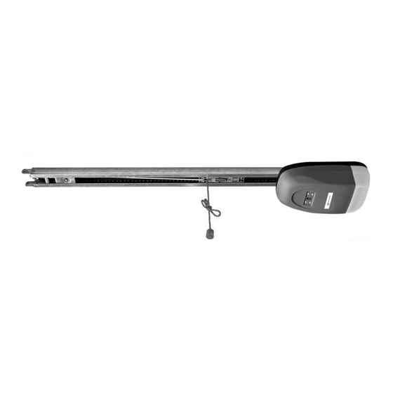
Garage door drive
Source: rademacher.de

Subscribe to Our Youtube Channel
Related Manuals for RADEMACHER RolloPort S2

Summary of Contents for RADEMACHER RolloPort S2
- Page 1 Garage door drive RolloPort S2 Translation of the Original Operating and Assembly Manual Item no: 4201 70 61 / 4202 70 61 VBD 543-02 (01.23)
-
Page 2: Dear Customers
...with your purchase of this garage door operator, The new RADEMACHER garage door operator you have decided for a quality product manufactured by RADEMACHER. We would like to thank you for your has been designed in an confidence. effort to the greatest possible ease of operation. -
Page 3: Table Of Contents
Content Programming ............. 21 Dear Customers............2 These instructions........... 2 Setting limits / setting the upper limit ....22 Setting the lower limit ........... 22 Key to Symbols ............2 Carry out reference run for power measurement ..23 General View ............ -
Page 4: General View
General View Operator, including lighting Hand transmitter 1st hand transmitter button 2nd hand transmitter button Set button (S) Display Button for adjustment (+) Button for adjustment (-) 10 = Programming button (P) -
Page 5: Supply Package
Supply package Please compare the contents of the pack- age with the content description on the packaging: 1 x Drive 1 x Operating instructions 2 x Micro hand transmitter 1 x Door connector, bent 2 x Middle support clip 3 x Fixing bracket 1 x Header bracket 1 x Door bracket 1 x Connector... -
Page 6: Safety Instructions
Safety instructions Failing to observe all of the information and Improper use increases the risk of injury. safety instructions contained in this manual ◆ Never reach into the moving door or into moving can lead to severe personal injury, e.g. by being parts. -
Page 7: Proper Use
Safety instructions Opener service life is 25.000 cycles. Important safety instructions. Each steel wire rope shall have a safety fac- It is important for the safety of persons to follow all tor not smaller than 6 (minimum breaking instructions. Save these instructions. strength / static load of one rope). -
Page 8: Improper Use
Improper use Incorrectly performed structural alterations Warning result in the risk of injury. ◆ The drive shall be disconnected from its power Do not carry out any structural alterations to the door source during cleaning, maintenance and when operator, the garage door or any existing safety equip- replacing parts. -
Page 9: Functional Description
Functional description Intelligent microcomputer Emergency release device Intelligent, computerized, exact positioning of travel, The door can be manually operated by pulling down on prompt power determination, reverses if obstructions the emergency release cable in the case of power are met. failure. -
Page 10: Functional Description / Recognition Of Obstructions
Functional description / Recognition of obstructions The door operator has an automatic obstacle-recognition system (through internal monitoring of power). If the door encounters an obstruction when closing or opening, the door operator stops the door automatically and moves it in the opposite direction until it reaches the corresponding limit. -
Page 11: Maintenance
Maintenance Defective door systems and safety equipment Check: result in the risk of injury. ◆ All screw connections to ensure they are tight For your safety, you should comply with the ◆ Cables for damage recommended maintenance intervals for your ◆... -
Page 12: Important Installation Instructions
Important installation instructions Important instructions for a safe installation. Faulty installation can result in serious ac- Follow all installation instructions carefully. cidents and injuries. An incorrect installation can lead to serious ◆ Fit the actuator for the emergency release at a height injuries. -
Page 13: Required Tools
Required tools You require the following tools Remove the door locks Remove all vertical and horizontal door locks and catches. IMPORTANT! Keep the „old“ door locks in a safe place. In the event that you should remove the garage door operator, you will have to fit these again in order to restore the original state of the door. -
Page 14: Take Measurements
Take measurements Measure up and mark the centre of the door Mark the centre of the door, as shown, on the upper edge of the door, on the door lintel and on the garage ceiling. Determine the distance between the top edge up-and-down of the door and the ceiling door... -
Page 15: Assembly Of The Rails
Assembly of the rails NOTE The RolloPort S2 is supplied with three rails: ◆ two end pieces, including a pre-assembled chain ◆ a middle piece (without a chain) with two connectors Lay the two end pieces with the pre- assembled chain on the ground, with the... -
Page 16: Connect The Door Operator Housing To The Rail
Connect the door operator housing to the rail IMPORTANT First of all insert the connector (5). Ensure that the microswitch (3) is not damaged when Place the rail (4) with the inboard chain mounting the rail. sprocket (supplied pre-assembled in the rail) over the connector (5). -
Page 17: Attachment Of The Door Operator And The Rail
Attachment of the door operator and the rail A / B / C / D refer to the following pages Installation on the lintel The installation should preferably be on the lintel, as Installation this means that the forces encountered can best be on the min. -
Page 18: (A) Installation Of The Header Bracket (1)
(A) Installation of the header bracket (1) NOTE The header bracket (1) must be aligned with the mid- point of the door. Mark out the position of the header bracket (1) and drill the mounting holes (e.g. with a Header bracket 10 mm masonry drill bit). -
Page 19: (C) Installation Of The Door Bracket (8)
(C) Installation of the door bracket (8) NOTE We recommend fixing the door bracket (8) to the door frame if possible. For plastic or thin-walled wooden doors, additional cross- beams are necessary in order to avoid damaging the door. In this case, consult your door supplier. Use existing drillholes, if possible, to mount the door bracket (8). -
Page 20: (D) Installation Of The Middle Support Clip (13)
(C) Installation of the door bracket (8) Screw the door bracket (8) tight with the enclosed self-tapping hexagon screws (8 x 15 mm). Finally, fix the door connector (12) to the door bracket (8) with the enclosed bolt (9). NOTE A straight door connector is supplied pre-assembled, and this is permanently fixed to the rail. -
Page 21: Important Notes After Installation
Important notes after installation ◆ After installation, ensure that the mechanism is properly ◆ After installation, ensure that the drive prevents or stops adjusted and that the drive reverses when the door the opening movement when the door is loaded with contacts a 50 mm high object placed on the floor a mass of 20 kg, fixed centrally on the bottom edge (for drives incorporating an entrapment protection... -
Page 22: Setting Limits / Setting The Upper Limit
Setting limits / setting the upper limit Carrying out the instructions in the wrong Correct setting order: order when setting the limits will result in 1. Set upper limit malfunctions. Be sure to keep to the setting 2. Set lower limit order specified. -
Page 23: Carry Out Reference Run For Power Measurement
Carry out reference run for power measurement During the reference run there is a risk of injury, as the door operator develops extremely strong forces. 1. Press „+“, the 2. Press „P“, 3. The door goes up display shows „3“. „3“... -
Page 24: Adjust Power Limiting As Required
Adjust power limiting as required NOTE If the power level is too low, the door move- The door operator is preset to stage 3 by the supplier. ment will be impaired, particularly if the mechanical structure of the door is not well If required (e.g. -
Page 25: Alarm Setting
Alarm setting If the alarm is switched on, the door opera- To end the beeping: tor beeps if the door is open for longer than Press the door control button to fully close the door. 10 minutes. The door operator beeps for 30 seconds every 10 minutes. -
Page 26: Automatic Closing Time Setting
Automatic closing time setting 5. Press „+“ and select 6. Press „P“ in order 7. Conclude programming the required closing time: to store the setting. (refer to page 27, method 2) 5 = 150 sec. 1 = 30 sec. 6 = 180 sec. 2 = 60 sec. -
Page 27: Conclude Programming
Conclude programming IMPORTANT NOTE Please note: this concluding step must be carried out, You can conclude the programming in two ways: otherwise the information stored will be lost. Method 1: Carry out this method without fail after the reference run. 1. -
Page 28: Registering And De-Registering Hand Transmitters
Registering and de-registering hand transmitters Registering hand transmitters: Both manual transmitters are already logged on to the large button on the garage door drive when in the factory. If you want to log on another manual transmitter, or have already logged off a manual transmitter that is included in the scope of supply and want to log it on again, proceed as follows. -
Page 29: Connecting Additional Electrical Equipment
It must be ensured that switch will result in a short circuit and will destroy the drive is not active if the door is not closed. the door operator’s electronics. RolloPort S2 ( 2 ) ( 3 ) ( 1 ) -
Page 30: Manual Door Operation
Manual door operation In the case of power failure: There is a risk of injury. The door can fall If you wish to manually operate the door in down uncontrollably when released (e.g. if the event of a power cut, you must pull the the door is not balanced) emergency release cable so that this releases the door from the door operator. -
Page 31: Instructions For The User
Instructions for the user Notes for use ◆ Check the operator system to determine whether it moves smoothly the first time the garage door operator is used. ◆ After some time in use, check regularly to see whether the door remains horizontal when opening and closing and whether the spring has enough power to lift the door. -
Page 32: Technical Specification
Technical Specification Model and recommended use Item no. Voltage (V) Door size (m Admissible ambient temperature (°C) 4201 70 61 ≤ 10 220 – 240 –20...+40 4202 70 61 Guide rail and available sizes Item no. max. total lenght Height of travel max. -
Page 33: Trouble Shooting
Trouble shooting Error Causes Solution 1. Plug the mains plug into the mains The door operator does not work. 1. The plug is not inserted properly. outlet. 2. The fuse has been tripped. 2. Have the cause checked by a quali- fied person, then switch the fuse back on again. -
Page 34: Simplified Eu Declaration Of Conformity
Simplified EU Declaration of Conformity RADEMACHER Geräte-Elektronik GmbH hereby declares that the RolloPort S2 complies with the Directives 2006/42/EC (Machinery directive) and 2014/53/EU (Radio Equipment Directive). The full text of the EU declaration of conformity is included with the product and is kept on file by the manufacturer. - Page 36 RADEMACHER Geräte-Elektronik GmbH Buschkamp 7 46414 Rhede (Germany)
Need help?
Do you have a question about the RolloPort S2 and is the answer not in the manual?
Questions and answers