Sign In
Upload
Download
Table of Contents
Contents
Add to my manuals
Delete from my manuals
Share
URL of this page:
HTML Link:
Bookmark this page
Add
Manual will be automatically added to "My Manuals"
Print this page
×
Bookmark added
×
Added to my manuals
Manuals
Brands
Malaguti Manuals
Motorcycle
XAM CE
Instruction manual
Malaguti XAM CE Instruction Manual
Hide thumbs
1
Table Of Contents
2
3
4
5
6
7
8
9
10
11
12
13
14
15
16
17
18
19
20
21
22
23
24
25
26
27
28
29
30
31
32
33
34
35
36
37
38
39
40
41
42
43
44
45
46
47
48
page
of
48
Go
/
48
Contents
Table of Contents
Bookmarks
Table of Contents
Table of Contents
Introduction
Welcome to Malaguti
Explanation
Safety Instructions
Safe Ride
Customer Information
Vehicle Identification Number (VIN)
Instruments & Operation
Representation of the Vehicle
Ignition Lock
Instrument Cluster (L1E-Version)
Handlebar Switch (L1E Version)
Instrument Cluster (CE-Version)
Handlebar Switch (CE Version)
Handlebar Lever
Side Stand
E-System
Charger
Charging Connection
Battery
Charging the Battery
Remove Battery
Chassis
Suspension Fork Adjustment
Adjusting the Shock Absorber
Inspection before Departure
Checklist
Drive Mode
Start Vehicle
Drive off
Accelerate & Decelerate
Brakes
Maintenance and Servicing
Selecting a Driving Mode
Parking
First Maintenance
Tyres
Rims
Brakes
Side Stand
Chassis
Steering
Wheel Bearing
Chain Tension
Battery
Fuses
Fault Detection
Care and Storage
Cleaning the Vehicle
Cleaning after Normal Use
Salt Purification
After Cleaning
Storage
Technical Data
Technical Data - XAM
Maintenance Plan
Declaration of Conformity
Spare Parts List
Space for Notes
Advertisement
Quick Links
Download this manual
English
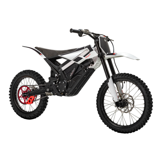
INSTRUCTION MANUAL
XAM (CE/L1E VERSION)
Version: 01 / March 2023
Table of
Contents
Previous
Page
Next
Page
1
2
3
4
5
Advertisement
Table of Contents
Need help?
Do you have a question about the XAM CE and is the answer not in the manual?
Ask a question
Questions and answers
Related Manuals for Malaguti XAM CE
Motorcycle Malaguti XTM 50 Workshop Manual
Chassis (42 pages)
Motorcycle Malaguti XSM 50 Workshop Manual
Chassis (42 pages)
Motorcycle Malaguti X3M User Manual
(292 pages)
Motorcycle Malaguti X3Motard Workshop Manual
125cc 4t euro3 (50 pages)
Motorcycle Malaguti XTM POWER UP 2007 Troubleshooting Manual
Electric system (53 pages)
Motorcycle Malaguti XTM 50 2007 Manual
(304 pages)
Motorcycle Malaguti Dune X 125 Service Station Manual
(273 pages)
Motorcycle Malaguti DUNE 125 User Manual
(112 pages)
Motorcycle Malaguti XAM L1E Instruction Manual
(48 pages)
Motorcycle Malaguti XSM125 2018 User Manual
(112 pages)
Motorcycle Malaguti XTM125 2018 User Manual
(112 pages)
Motorcycle Malaguti CNK 50 DRAKON Workshop Manual
(80 pages)
Motorcycle Malaguti Fast Time F-10 50cc Repair Manual
(151 pages)
Motorcycle Malaguti MADISON 125 Manual
(303 pages)
Motorcycle Malaguti GRIZZLY Owner's Manual
(173 pages)
Motorcycle Malaguti centro 160 ie User Manual
(242 pages)
This manual is also suitable for:
Xam l1e
Table of Contents
Print
Rename the bookmark
Delete bookmark?
Delete from my manuals?
Login
Sign In
OR
Sign in with Facebook
Sign in with Google
Upload manual
Upload from disk
Upload from URL


Need help?
Do you have a question about the XAM CE and is the answer not in the manual?
Questions and answers